A few years ago, I wanted to create a device to measure the current being consumed in my home. This isn’t a particularly new idea, especially with rising energy prices - having some sort of feedback on what you’re doing can help reduce unecessary useage.
There are a number of devices and systems out there that already do this, including some that can access the information from an electronic meter connected to the mains supply of a house. These are meant for Joe and Jane Average, and often rely on proprietary backends to do their work and don’t expose any kind of data that can be placed into a historian. If they do expose data, then again, you’re relying on someone else’s computer and your internet connection to provide said data, and those systems may change or go away at any time.
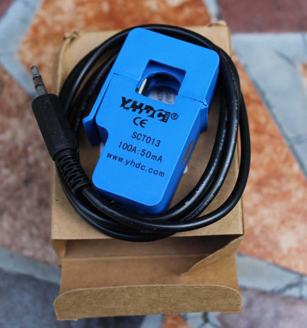
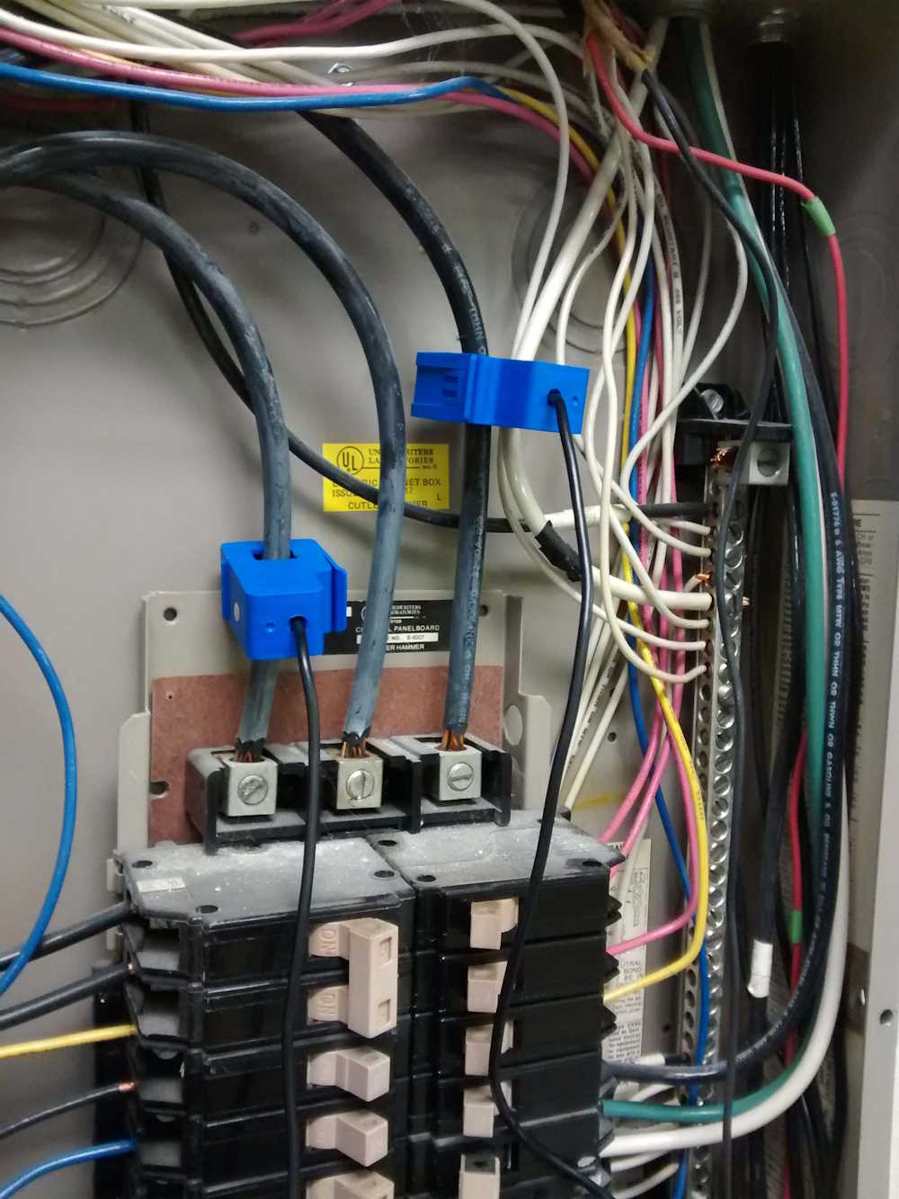
The goal, then, was to create something that could provide a universal data output that could be connected to any device capable of reading said output. An analog voltage from an analog circuit was chosen, both due to the instantaneous response, the the availability of cheap current transformers, such as the one in this picture. This device simply snaps around an incoming AC line, and provides a physically isolated output of either (in this case) current, or voltage.
This solves the biggest problem of how to get the measured current out of the fusebox without cutting AC lines. I’ve chosen voltage output devices for this particular project, and since the voltage output is small (usually in the mV range for full scale,) the first thing to do is amplify it a bit. This is accomplished with a standard op-amp circuit with a gain of 10-20, depending on the current transformer chosen. This also gives a bit of isolation, but that’s not really necessary at this point.
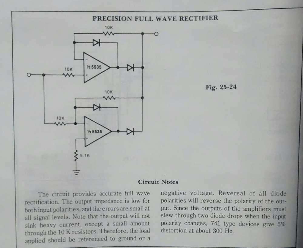
Next is how to feed this into something that a hobbyist would have access to. Measuring DC is much easier than measuring AC with commonly available microcontrollers, so the problem to solve is converting this signal to DC. This can be done with a simple bridge rectifier circuit, but I prefer to use something I found years ago in one of those “Big Books of Circuits” that TAB Books used to publish. The circuit in question is called a precision rectifier circuit, and the goal is to output a signal similar to the input, while minimizing losses. It works well enough, and a small capacitor and resistor on the output gives a decently filtered DC signal with fast-enough response.
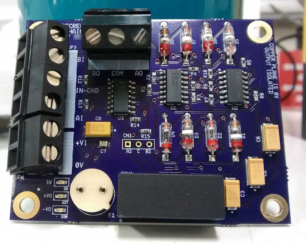
While I’ve built this circuit on bread- and protoboards many times, I decided to lay this one out on a board.
The board turned out ok, but now that I have more experience with layout, I’m not really happy with it. But it works, and all of the germanium glass diodes used as rectifiers provide a rather cool look. I’m going to go with shottky diodes for the next round, simply because germaniums are getting harder to find and the shottkys are better at handling even the low slew rate of a 60Hz signal.
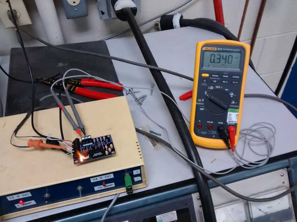
Two remaining tasks at the time were to test the board and it’s output, and to choose a microcontroller platform. Testing was easy, the project had originally found a home at a former employer as a monitor for air compressors - the company wanted to run tests over the weekend requiring compressed air, but needed to know if the compressors were to become locked in an on state (which would subsequently result in overheating and damage.) I did the initial testing in the fusebox for the compressors, and was able to translate the resulting DC output into a correct current draw. The employer then lost interest as it was revealed this was going to cost more than nothing to fully develop. I had to abandon the project as the business slowed and let people go while the sky was falling.
For the next round, I’m planning on trying out some of the new microcontroller options on the market, especially the Raspberry Pi Pico. This is a fast, dual-core Arduino-like that’s extremely inexpensive, and has an Ethernet onboard option offered by a third party. My original design choice was to use an ESP8266, but that didn’t go well, so was abandoned. Read this entry for my misadventures with the ESP controllers: https://pygg.xyz/pro … of-cheap-technology/. A new board with multiple channels of input is in the works, and will offer a better onboard ADC as well as some user amenities like a display. Stay tuned for the next update!
(Future me update: There are plenty of zigbee devices that do this now, I’m no longer pursing my own solution.)
I found this photograph with the Audio Baton photographs, and thought I’d share. This is a group photo of the OS/Other area at the Columbus Works, just as the facility was moving to Lucent Technologies from AT&T.
OS/Other was the area where Craft Access (telephone system test equipment) was built, tested, and repaired. We had a wide range of products, including:
MLT-II, Mechanized Loop Test
DCTU, Directly Connected Test Unit
CAROT, Centralized Automated Reporting on Trunks
TNC, Telemetry Network Controller
GTP, General Telemetry Processor
ARSB, Automated Repair Service Bureau
J1x frames of various types
A lot of other stuff I’ve forgotten
It was a fascinating area to be thrown into, the age and type of equipment was a who’s who from the bygone ages of telephone switching equipment. To the best of my knowledge, most of the product lines were EOL’d, with some like the DCTU being sent to another location (DCTU went to the Kansas City Works) before being EOL’d at that location.
I have to say I miss working with the people there, and the equipment we had. Just the sheer scale of the operation made it something special, and I’ve always wondered if there is any place like that left today. Who knows, I guess.
August 5th 2025 - The above link is fixed, sorry about that!
A long time ago when eBay was still fairly new, a set of heavily modified Blonder-Tongue Audio Batons showed up for a cheap price. These are the first commercially available graphic equalizer, featuring 9 bands. Tube complement for this device is 5 12AX7 used as amplifiers in the EQ stages, and 1 6X4 rectifier to provide power for the unit. 3 lamps to backlight the adjustments ran off the AC filament transformer.
I’m not sure what was going on with these units, but two of the potentiometer holes were punched out on one of the chassis, and two extra tubes had been installed. Multiple modifications had been made to the electronics, which were in somewhat of a state of decay. Old carbon comp resistors had drifted, capacitors had become leaky, and all of the mods just made a mess of the unit. The other unit didn’t have mods, but the electronics were in the same state of decay.
The first thing I did was remove all the components except for sockets, transformer, and terminal strips. New components were purchased, including orange drops and mylar film capacitors, carbon film resistors, and of course, new wire. Holed punched in the chassis were re-filled with washers of the correct size. Potentiometers were saved where possible and cleaned. The chassis were re-wired and all of the new components were placed. I decided to do my own layout and wound up with a more compact layout than the OEM layout.
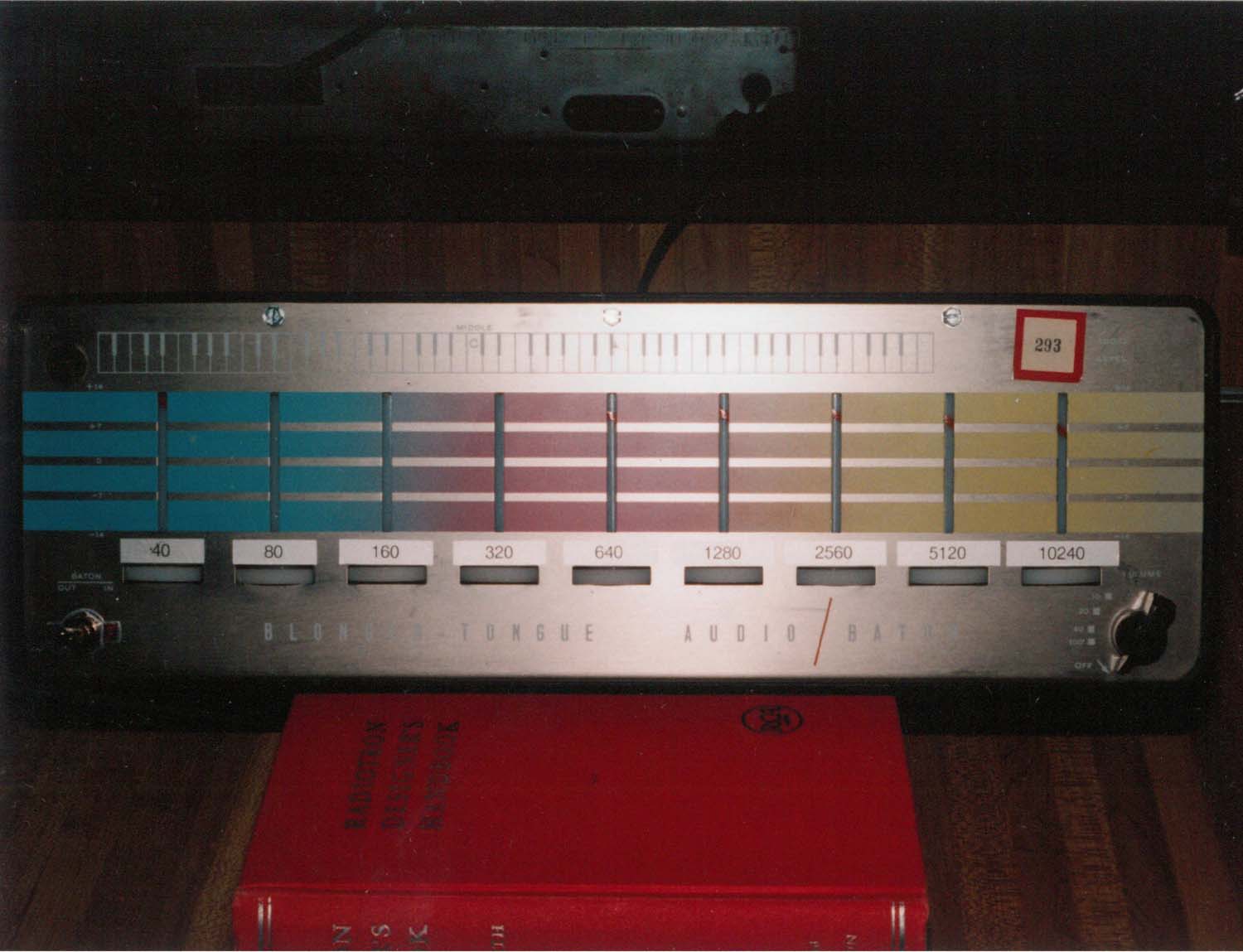
The original case, of which I had one, used weird bi-pin lamps to backlight plastic tubes with a candy-cane stripe on it. The stripe appeared in a slot cut in the face, and as you turned the pot the stripe “moved” up the slot. This was re-assembled and, unfortunately since the face had been damaged, I used stick-on labels to identify the bands. The odd number sticker was left on the face. I assume this is from a previous auction.
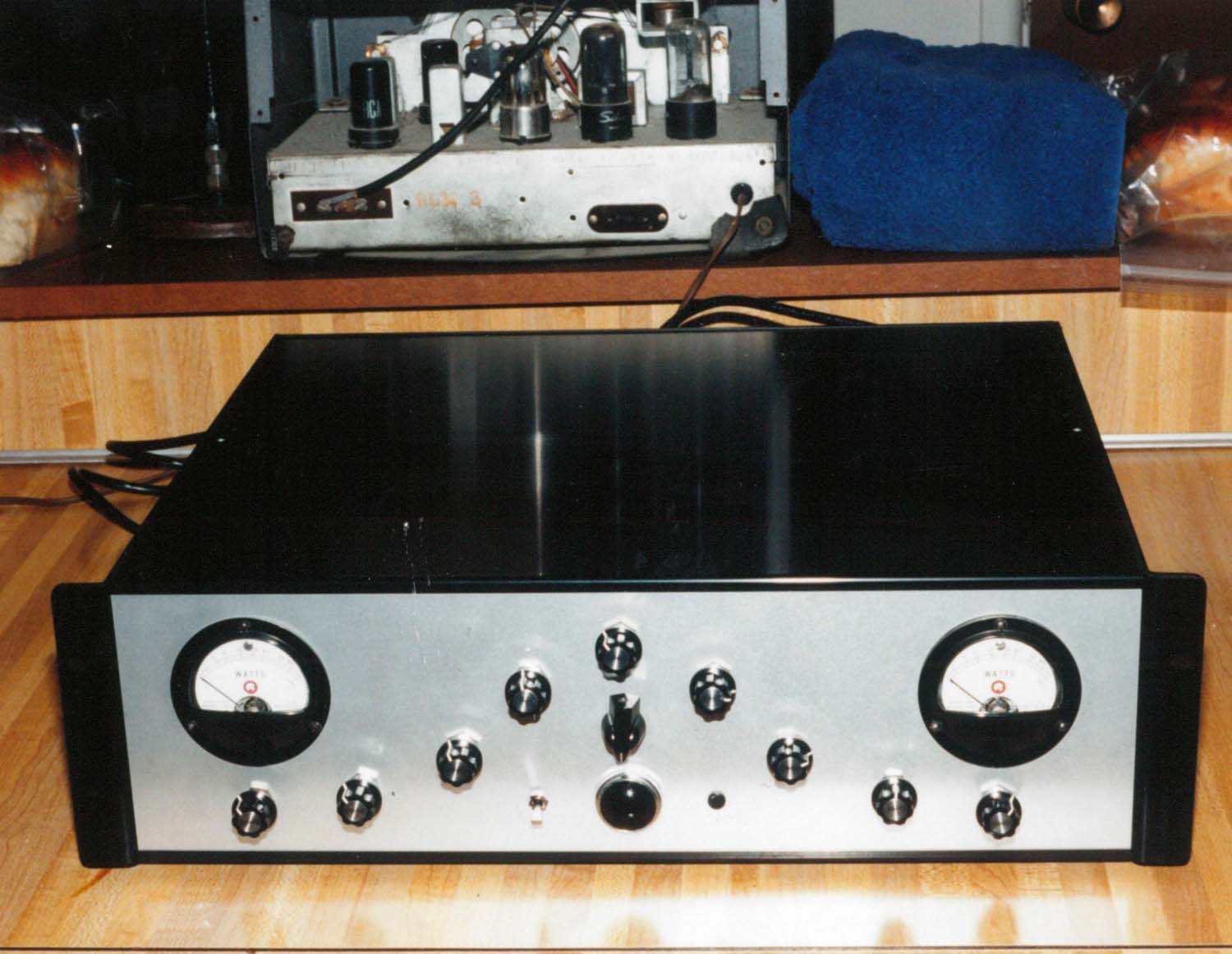
The second chassis was more of a challenge. Since I didn’t have a case, I settled on a rack chassis from SES-COM, a company that used to manufacture such items but has since transitioned to audio products. More space allowed for some added some amenities such as VU meters using a precision rectifier circuit and a push-on/off control circuit for both units. I replaced tubes as needed, using NOS RCA and other brands as available in my personal stock. A final check, and they worked - probably just as good or better than new.
I was never able to determine what the mods were, save that I’ve seen others reference strange mods where the chassis was punched out and extra tubes added.
In the end, there was more fun had rebuilding these units as opposed to using them. They’re simply graphic EQs that consume a lot of power and have the added noise of a tube circuit. A modern unit works just as well, and has more bands. I ended up relisting them on eBay around 1998 (I think?) and selling them to a studio. That’s something I kind of regret, but as I said - in the end it’s just an old version of a new circuit.
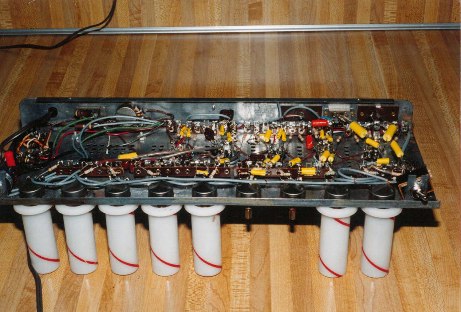
Unfortunately, since this build pre-dated digital cameras, all I have left are these photographs taken with a friend’s Samsung point-n-shoot. They’re not the best, but here they are.
The underside of one of the chassis units:
The chassis inside one of the OEM cases. I only received one case and two very mangled chassis units.
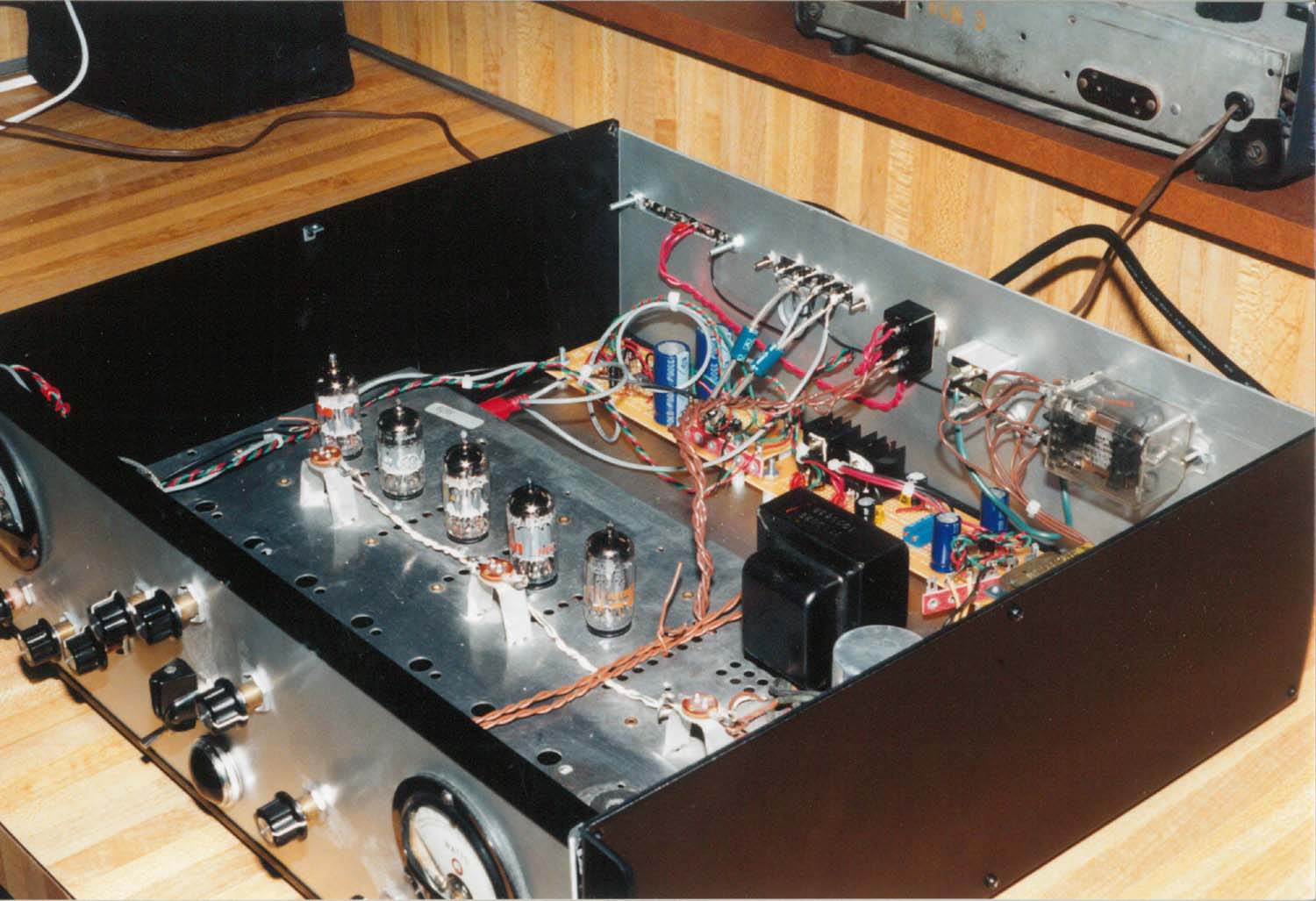
I put the other chassis in a rack case, added some level meters, and made it so both units ran off the same AC input. The rack chassis came from SESCOM.
Here’s the entire device, cased and ready to mount. It needs some labels…
If you happen to have these, please contact me on Linkedn or Mastodon. I don’t want them back, I’d just like to know if they’re still in use. However, if you want to sell, let me know!
I was really surprised how good this show was. Here’s my haul of junk treasure from the show. I took $200 and spent pretty much that. There were some other things I was eyeing, but had to leave them as they were mostly cool toys that had limited to no use. The only thing I wish had been there was a battery vendor so I could pick up a new battery pack for my two-way.
This is a show, barring other commitments, that I will attend next year as well.
Pictures of the main event coming shortly.
An Eico VTVM. Just a nice, big meter.
An RF Generator. Will replace a cheap unit that doesn't.
An Eico Capacitance Bridge for spare parts.
An HP DVM with bubble LEDs, and a wierd power supply. Both cheap!
An almost new Weller solder gun, a nice Panavise PCB unit, and my poor Yaesu FT-60 in the background wishing I found a new battery for it.
A neat RCA reference book and some parts from the dollar bins.
A portable Superior Tube Tester. It looks to have never been used.
My ticket. I'll stick this in a piece of equipment.
I wasn’t sure about attending this one, but I have to say that it turned out to be an excellent small show. I planned on an hour or two, but it rapidly turned into a “stay until almost close” event. There was quite a lot to see, a good crowd of people, and as always, I brought home way too much junk treasure. This is an event that I’ll probably put on the attendance schedule for next year assuming we’re not all afraid of the sun coming up in the morning like last year.
The only thing this show didn’t have (beyond a few parts vendors) was a vendor selling new equipment. But that’s ok, that can be had elsewhere. We’re here for the good junk. And there was a lot of it.
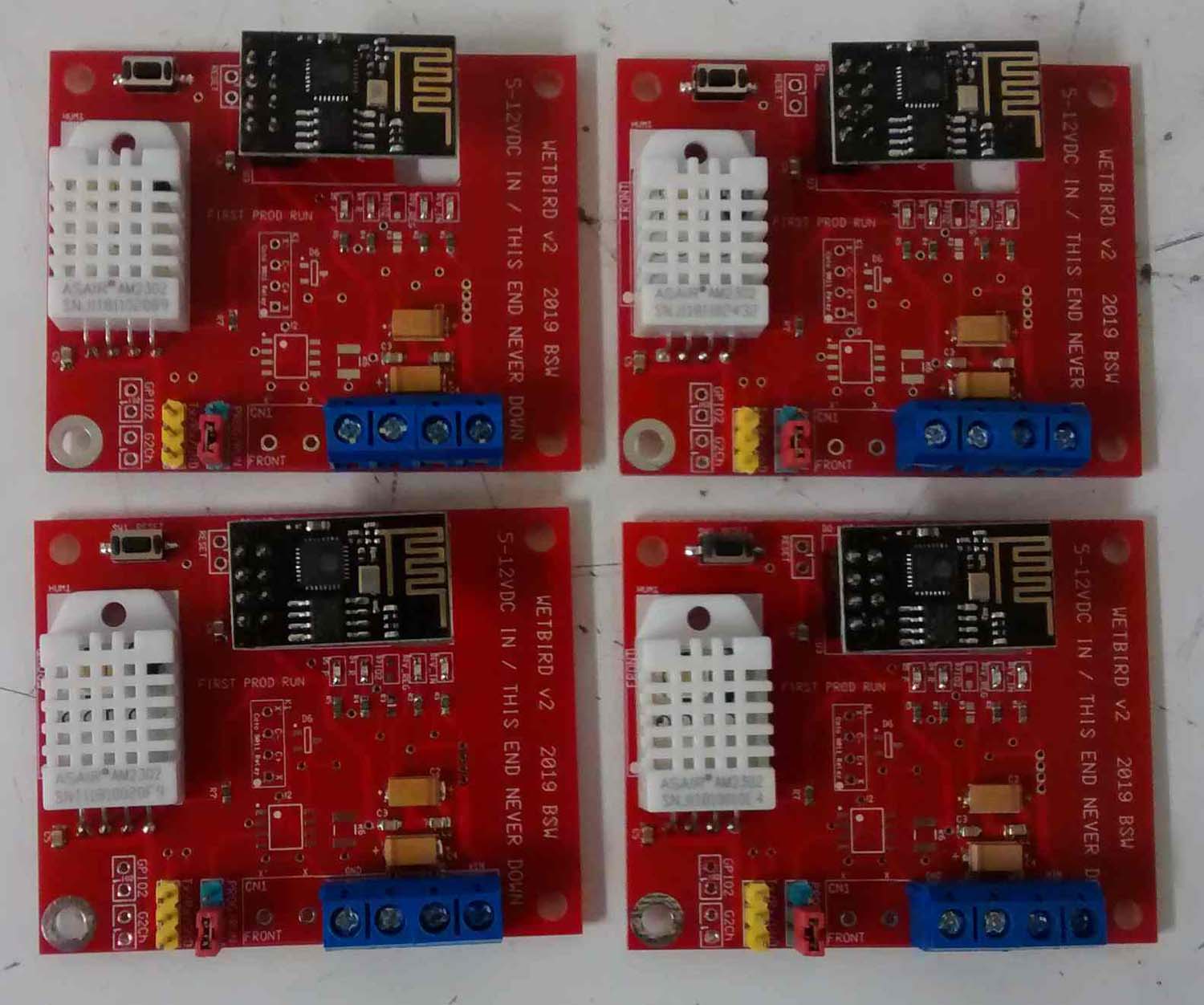
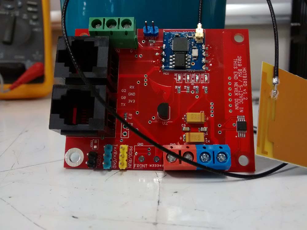
Some time ago, I had the idea that I’d like to develop something with the popular and inexpensive ESP line of microcontrollers. These offered a mature WiFi stack, a relatively large amount of program space, and were available in many easy to use packages that include a very cost-effective pin header version. I came up with a standardized board, and called them birds because apparently some people believe birds aren’t real and are simply monitoring devices….
The original production run Wetbird device.
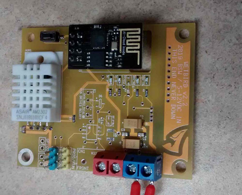
Version 2.2, cleaned up a little.
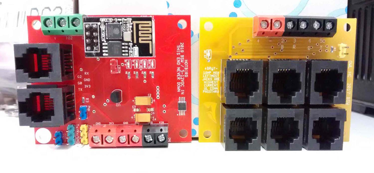
A Hotbird temp device and an OWL expansion board.
A Hotbird using an unobtanium ESP-002.
One of the things that I didn’t do during the development stage is pull the FCC paperwork for the device. Device is kind of a misnomer here, since there are multiple devices and only the chipset in a particular configuration seems to be certified. Had I done that, this probably would have been avoided.
I had designed and deployed a number of different boards to do temperature and humidity testing around the house. When I started to have issues with other systems, there were probably about 10 units operating in various capacities. However…
My first clue that something was amiss was the fact that my garage door opener had started acting up. It being several years old, I blamed age and potentially some new radio equipment installed at a nearby airport. This device operates at 320MHz… The next clue was that my old RF X10 control system had quit responding to the controller, and refused to operate no matter what module or receiver I tried. Since I had NOS devices available, and they didn’t work, I figured there was something amiss here. The X10 devices operate on 310MHz in the USA…
So what had changed? On investigation, I noticed that the signal indicator on the garage door opener was solid on, indicating it was receiving something. I still wasn’t sure what was going on, but I ran into another issue. The humidity sensor I used on the boards, a cheap device commonly available in the hobby market, had started failing. They would quit responding (sometimes!) and come back with a power cycle. I took them offline to try and troubleshoot the problem, and every other system started working again.
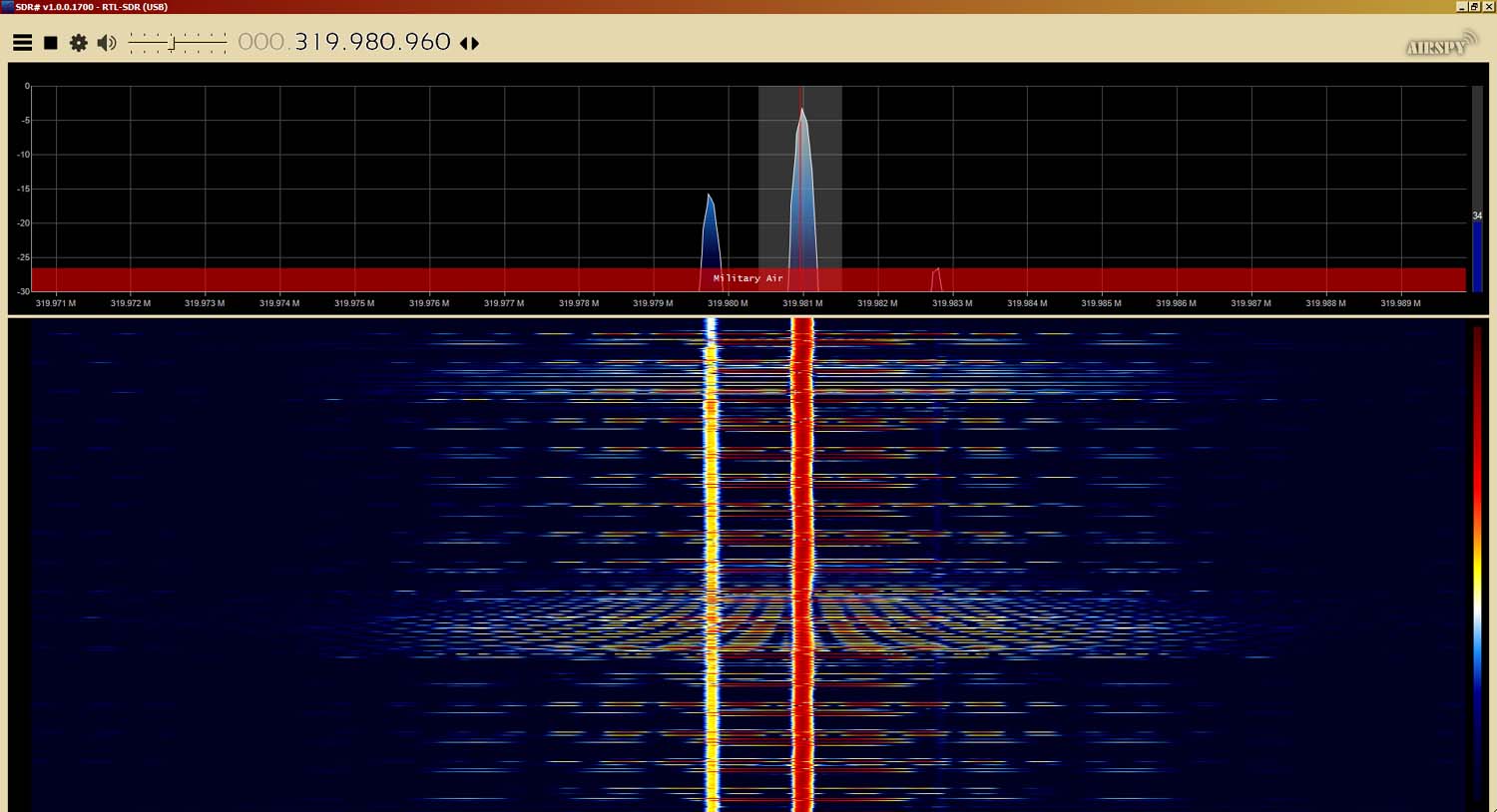
On a hunch, I grabbed my cheap SDR stick and set it up to look at the spectrum from about 305-325MHz. And right there it was, a big spur at 319.98MHz. Close enough to the opener’s frequency to kill it, and wideband enough to interfere with the X10 system’s unfiltered receiver. I took the few remaining devices offline and everything went back to normal.
It turns out that there are a number of spurs emitted by the ESP chipset. One of those, the important one for my testing, was right around 319.98MHz. You can view that particular document here: https://fccid.io/2ANHN-ESP8266 but note the device tested doesn’t look anything like the ones available for consumption.
This is a crying shame, because the ESP chipset shows up in many places and is so cheap and easy to use. The next available alternative is the Arduino WiFi devices, but those are fairly expensive at $50ish, and still have certain issues that have been poking around for years.
For now, I’ve shelved that project but have thought about reviving it. The new RP2040 chipset is available with a wired interface for about $10, and while it won’t be as easily deployed as a wireless device, the wired connection insures it won’t have any spurs knocking my garage door opener off the air.