I’ve removed the old range switch and will stash it for later. I’ve also started removing old parts and identifying wires to replace and other items that need a bit of attention. This will probably run a couple of parts before we start re-placing components…stay tuned!
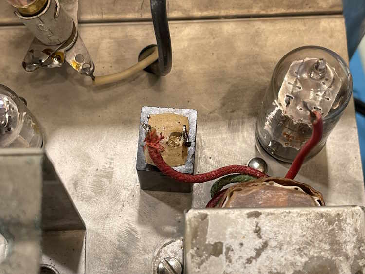
Now that we’ve determined what the EICO 249 needs as far as rectifiers, it’s time to actually replace it. Here’s the part that’s leaving us:
And it’s mount. The part itself has a stud on the back that’s being used for a terminal strip.
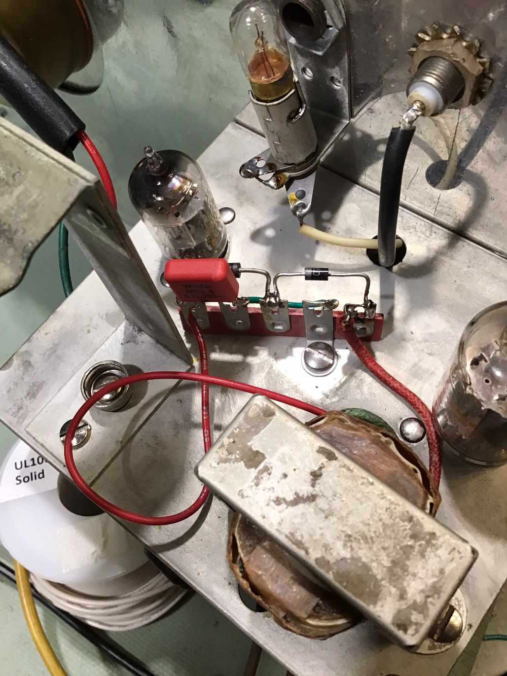
A 1N4007 and a 5W, 20V zener were used to simulate the voltage drop of the selenium part. There’s also a capacitor there, we’ll get to that in a minute.
B+ and B- are both good, although B- is a little low. It’s still fine and gives plenty of room for AC Zero. The output wire is long because it will get laid in properly later, and I wanted plenty of length.
I was reminded that the measurements in the manual were probably taken with a loaded-down meter, and that may not reflect what we see here. So, I’m happy with the results.
So, why the capacitor in the circuit?
Because, this:
That’s noise measured right off the end of the zener. Diodes can create noise that you didn’t see in tube circuits, and that don’t matter in solid-state because we bypass the noise away. That’s what this capacitor is, it’s a shunt to ground for the high-frequency noise that may be present on the rectifier.
The noise is all over the signal in the unit, and if you zoom in with a better scope it’s about ~2KHz.
We just have that pervasive 60Hz hum that’s everywhere in a device like this after the capacitor is added. A bit more filtering on the power supply, and we get this:
That’s as good as it’s going to get, and is probably 100x better (or more!) than the OEM would have provided.
The meter itself is working fine, so now it’s time to do the fun stuff. Next few posts are just teardown and prep, stay tuned!
The range switch is finished, so it’s time to move on. I did some calculations over the past week in order to see what is needed to replace the selenium rectifier, those will show up soon. I’ve also done a short video talking about the device, and where we go from here.
Next part of this series: Coming soon.
Previous part of this series:
Wrapup and final thoughts: Coming soon.
After much consideration on how to get the stuck knob off, I decided on just wrapping some wire around it and pulling. That did it, and it eventually slid off. Not sure why it was stuck so firmly, the shaft it was on didn’t show any signs of corrosion that would make it stick. I guess it was just firmly on there!
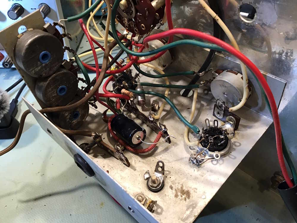
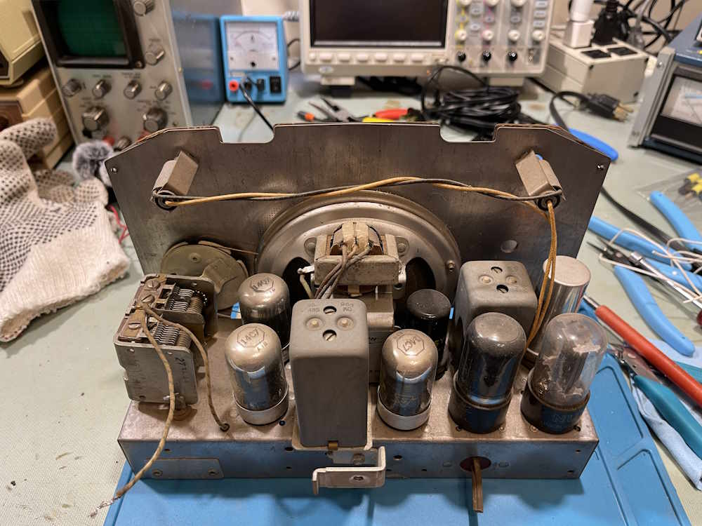
The chassis has had a little work, not much, and it’s mostly unmolested inside.
There’s a bit of burnoff on the tubes, so it has some hours on it’s replacement set.
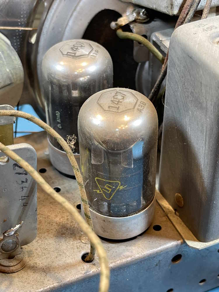
It’s full of loctals. Sylvania-branded, RCA-made.
The only two things I see in here that have been messed with are the main filter, and a capacitor on the chassis:
The rest of the capacitors are going to need replaced, however. Such lovelies as this popped end…
And this delicious sugar covered caramel beauty:
This one is just going to need the standard old radio stuff, and that’s going to happen later. Stay tuned!
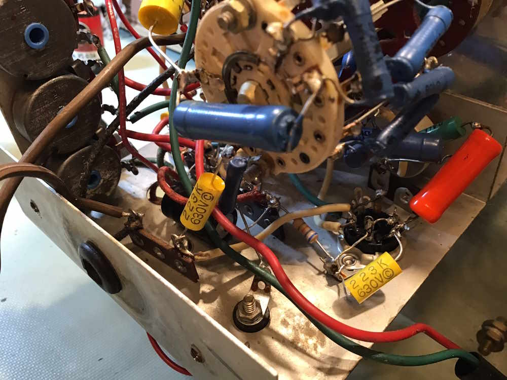
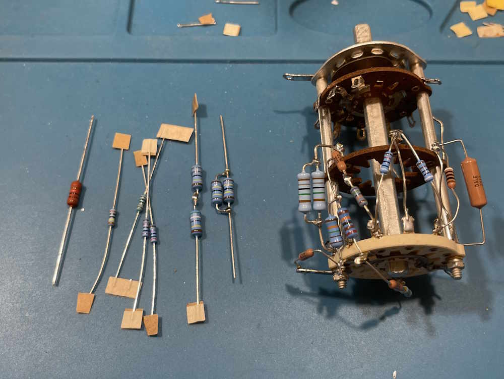
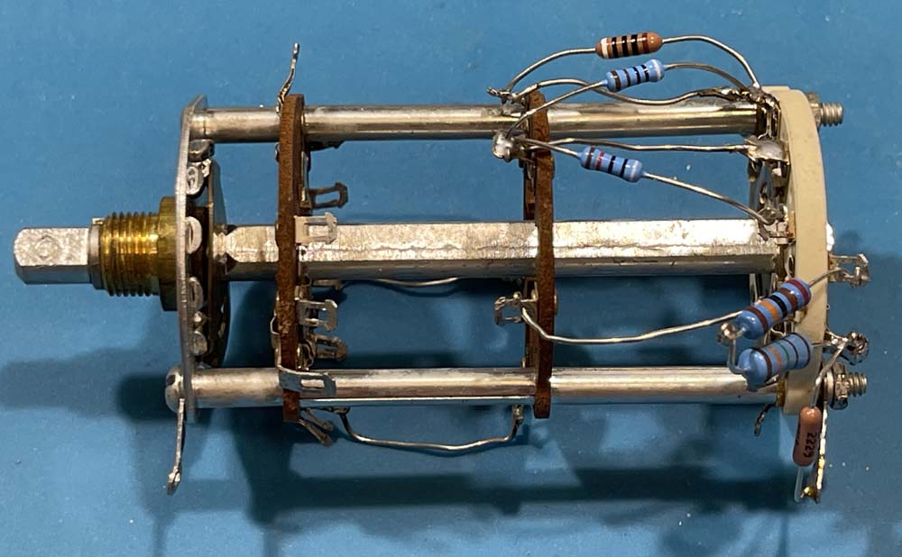
Seeing as how the range switch rebuiild is going much better than I expected, I decided to go ahead and prep the remaing resistors, and install them. This is what I was looking at for this part:
I had some resistors, some had to be made from others.
Installing them came up with this. The only thing I decided to change was to move a 10kΩ from the inside of the switch to the outside, as it wasn’t really long enough to do it like the manual called out (even though I could have easily extended the leads.)
I went ahead and installed all of the flying wires, but didn’t do the remaining parts on the bottom that fly off the terminals. There’s a 0.1μF 1000V capacitor, a 0.0025μF capacitor, and a 9.7Ω resistor that was made from two values. Those will be installed during the actual rebuild so I can size their leads appropriately.
With that out of the way, I took a look at some other mods that are going into the unit. The first is where the AC line comes in to the device. I’m going to change this terminal strip to a 4 position so I can add an across-the-line capacitor, and get the AC line cord off the main switch.
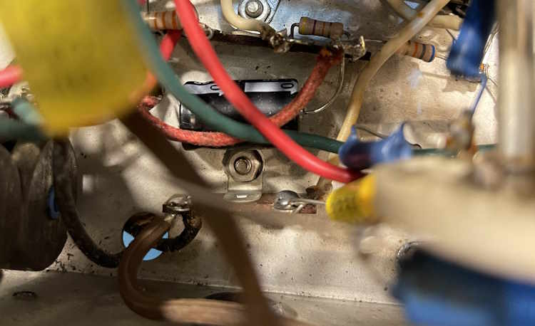
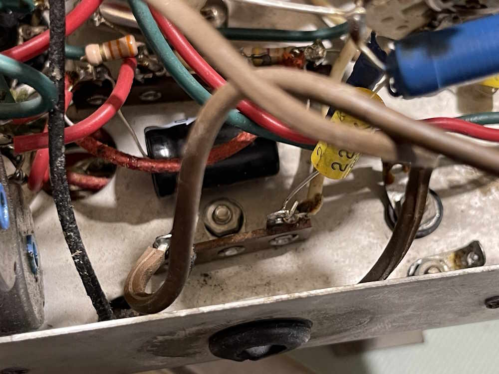
The other item, not really a mod, but still: I have no idea what this capacitor is for.
This comes off of pin 7 of the 12AU7 (grid) - was the previous owner trying to fix a noise issue? There may be a mod out there somewhere that specifies placing this capacitor to do just that, but I have not found it. Admittedly, I haven’t looked much, but it will probably be removed. There is a capacitor on the other side of the tube…perhaps if one is good then two is better?
Notes: I did some research on this and yes, that capacitor is there to help bring transient noise to ground. I’ll put a fresh part in during the rebuild.
I’m going to do some testing on the power supply before proceeding, stay tuned!
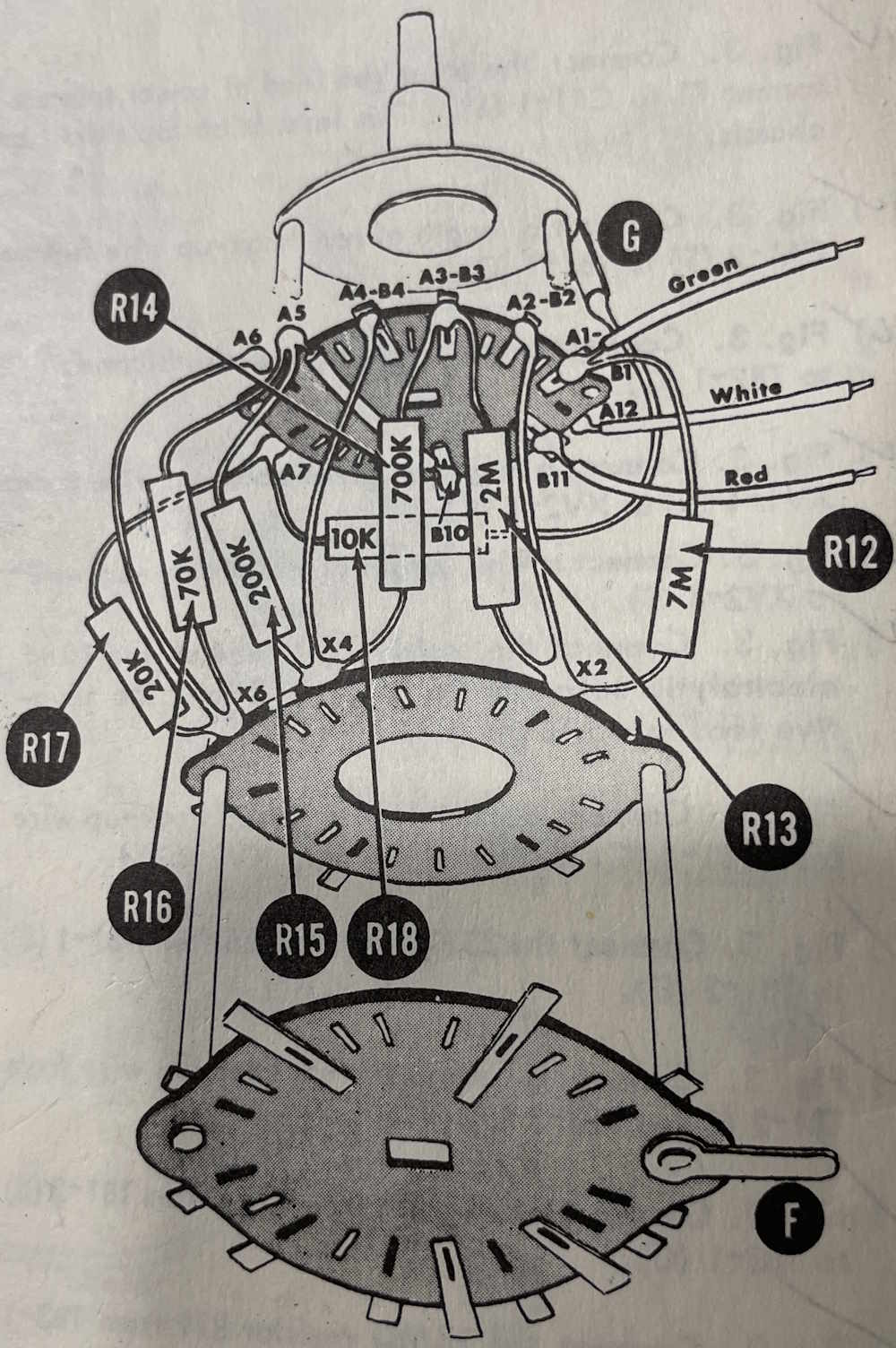
There’s a lot of resistors on the range switch of this device, and that’s really the reason I was putting off the rebuild. It looked quite daunting, but so far (once I figured out how they were referencing terminal names) it’s been going fairly quickly.
For this part, I installed the remaining resistors on the bottom deck, save the parts that are flying off the switch - those will come later. Since most of these are odd values, I had to make a few, including the 9MΩ, and 900kΩ. These were made from paralleling two 18MΩ for the first, and series of a 750kΩ and 150kΩ for the second. The other parts, I was able to get as is.
I’m going to try and finish the upper deck in one go and then start on the main body of the unit. Stay tuned!
This unit is an example of a very common meter - the RCA (VIZ) Senior VoltOhmyst. These are everywhere, and I’ve had two others come across the bench in the last year, both of which were not recoverable. I suspect this one, while it probably works, has similar issues.
This is a generic multimeter that features two tubes, a 6AL5 rectifier, and a 12AU7 as the input amp to provide that high-impedance isolation. (This tube was missing when I got it, because people love 12AU7.) This unit is kind of unusual in that it is RCA branded, most of them I’ve seen were VIZ branded.
It’s in relatively good shape.
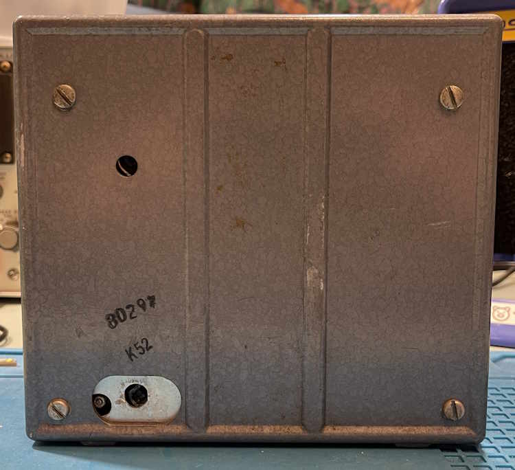
The back is a little beat up, and I had to cut that old grommet out to get the rest of the damaged power cord removed from the unit.
Inside, we find an OEM RCA battery. That’s cool.
This battery, of course, is for the ohms circuit.
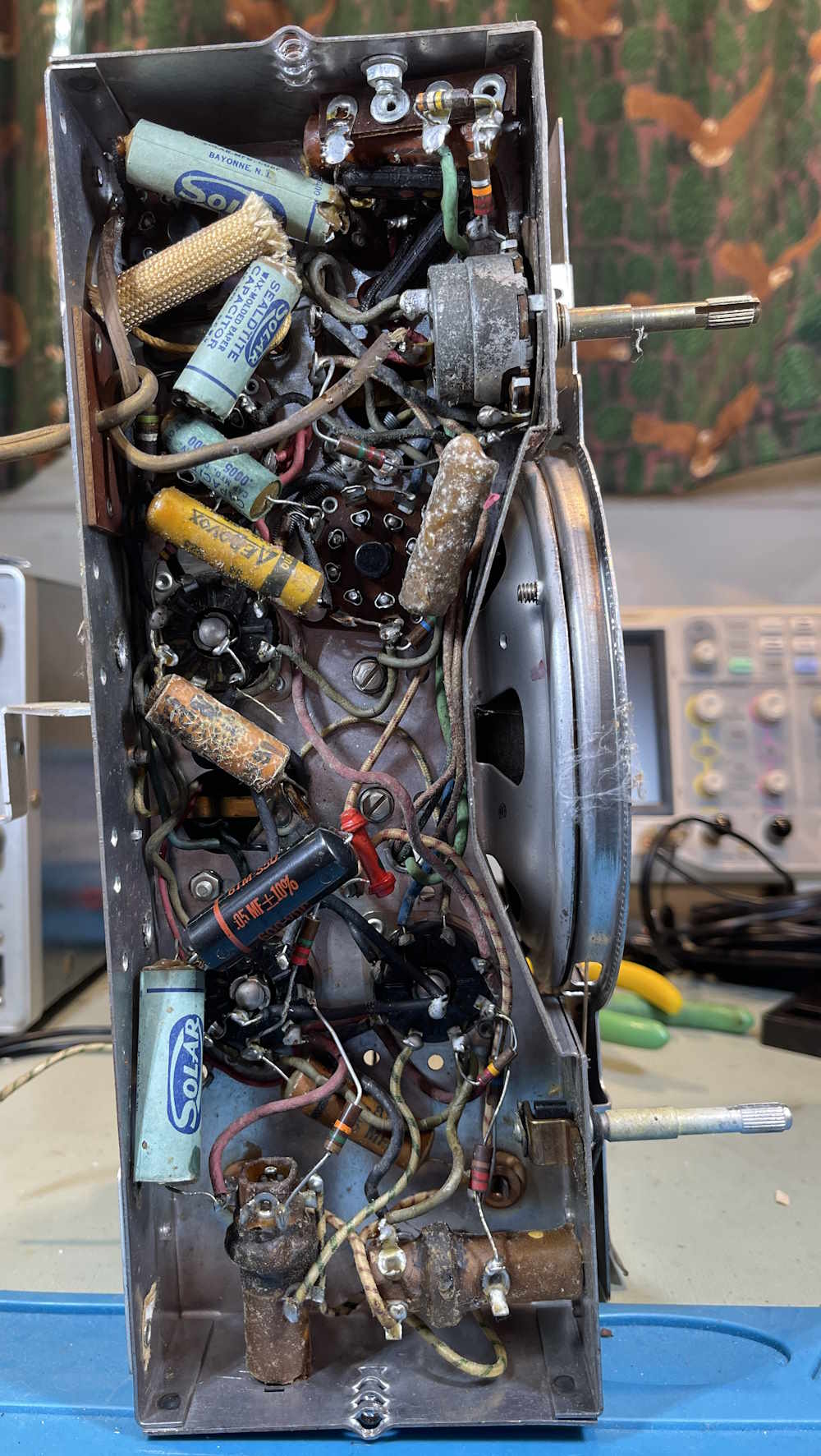
It has a lovely (joke!) selenium rectifier at the top, next to the old-school RCA meatball.
The board was laid out by hand of course,
And the rest is all wire.
So, does it work?
Yes. Mostly. It’s way off in reading, and that’s because of something that’s typically wrong with these. It also has a sticky meter, which kind of negates any usefulness.
So what’s the “typically” on these?
Carbon film resistors. That’s what’s wrong. These were 1% when new, but have all drifted. Even if they have not, the minute you touch a neighbor to remove it, the values of the ones touching it will change. A lot.
So…I’m not sure I am going to do anything with this other than set it on a shelf for a display. I hate to do that, but it’s of limited use and has some fatal flaws. I probably should have kept the other ones I had, but … whatever.
Stay tuned, this one may show up when some backlog has been cleared. Who knows?
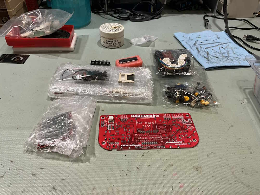
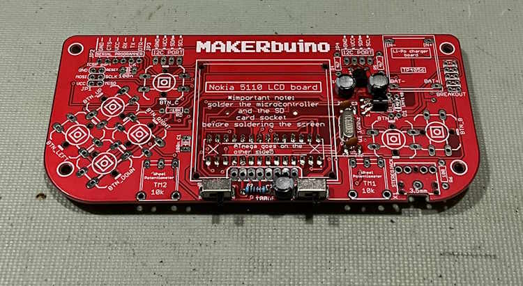
Some long time ago, I picked up a kit called a MAKERbuino. As you can probably tell, this is from the time period when anyone who did stuff at home as a hobby was suddenly a “maker” and not a hobbyist. Since it’s been kicking around the shop for a while, I decided to get it out and assemble it (along with some other kits that have been similarly hanging around.)
Here’s the kit itself:
The kit consists of a:
Circuit board
Display
Buttons
Parts
Case w/battery
There’s also a radio kit in the background, that one will show up soon.
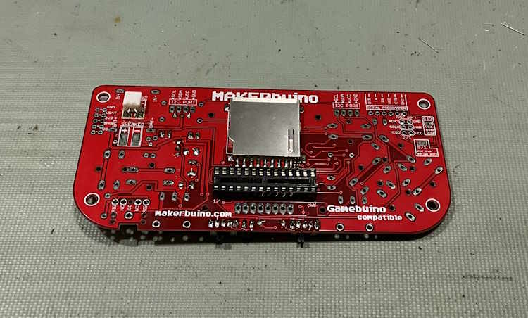
The board comes with the battery connector already soldered, so I started going down the assembly instructions:
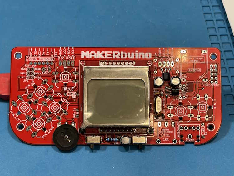
The way this one works is you proceed to a certain step (#12) and bring it up. It should come up to an adjustment screen, at which point you’re safe to proceed with the rest of the assembly. (I did add the control for the backlight, just in case…)
Mine did not do this.
The display, while lit, was blank. I could see what looked like the grid lit, but nothing else. However, after a little while, the screen started flickering to life, so I hit it with a little heat and it came alive. Touching it would send it into convulsions, so I’ve come to the conclusion that the screen is probably bad.
This is just a Nokia display. I had some similar units in stock, but they’re just different enough that they didn’t work. So, I’m stuck at this point. I reached out to the kit vendor, and they said that parts were no longer available for this unit as it was quite old. No surprise there.
I’ll see if I can find this particular style of Nokia display in surplus. Until then, stay tuned!
Pygg.xyz is where this blog started after being moved from blogger.com. It wasn’t a good look, unfortunately…anything xyz is pretty much automatically sus (non-scrofa, of course) and didn’t pass the smell test. That’s why you’re here on wereboar.com.
If you still have any pygg.xyz bookmarks, you can safely remove them. The registrar now owns the domain, and they’ll probably load it with ads like registrars do when it’s a parking page.
Thanks for stopping by, and I hope you find something of interest here.
I’ve put this one off long enough. It’s time to get this one done, and let’s call this one part 4a. Hopefully I can get this portion of the rebuild done in 3 parts…
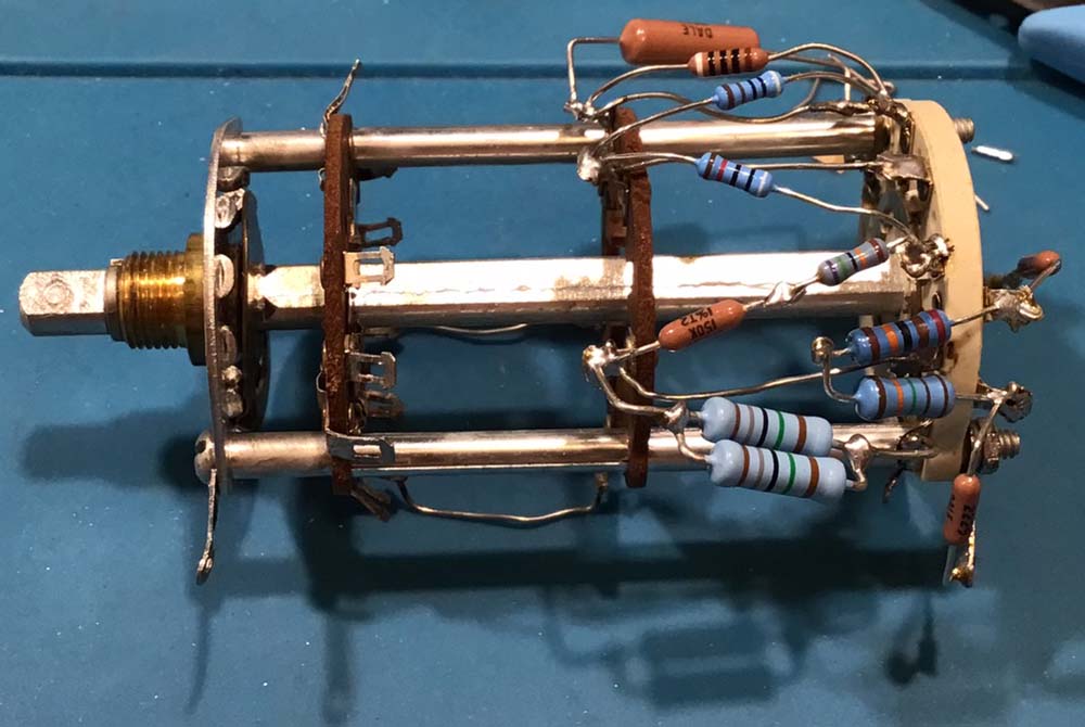
This unit is going to require a complete overhaul, including every resistor on the range switch (and then some!) So let’s start with the range switch.
Since almost all of these resistors were custom values, I’ve ended up having to make some of them. There’s an easy way to do that, you can use standard values and a special calculator site:
This site searches standard values and tries to come up with a solution using two resistors. I was able to make all of my hard-to-find resistors (I’ll publish that chart in the wrapup,) except for one. That one was 82MΩ, which is an odd value. There’s limited selection on that one at best, so I made one out of four resistors.
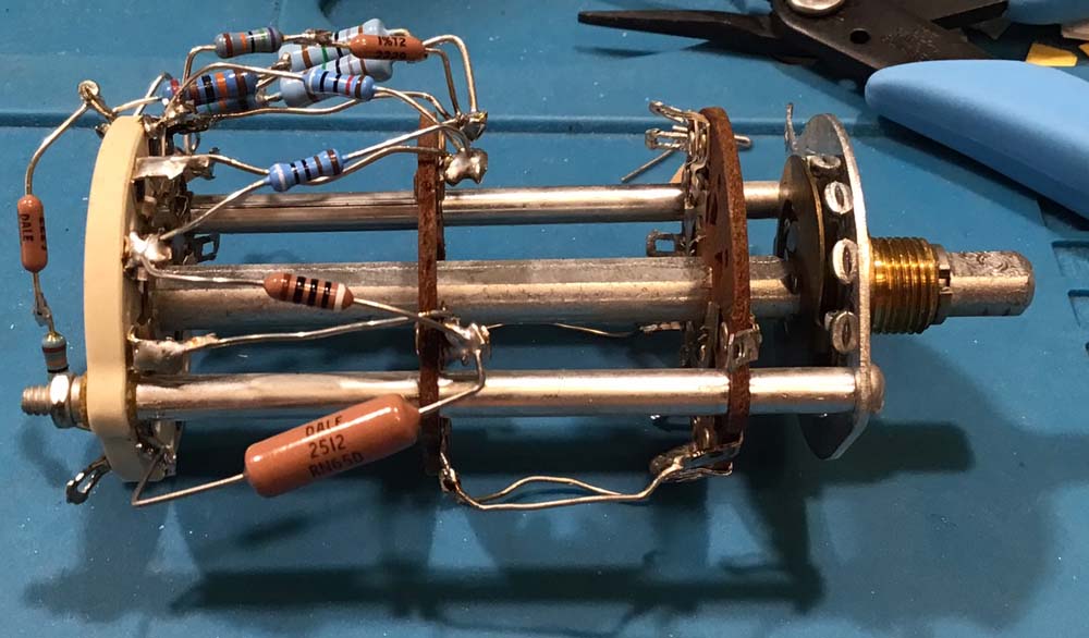
I don’t have all of the resistors I need yet, but I had enough to get started on the switch. This is what I came up with:
I’m going to try and do maybe 5-6 resistors at a time so there’s no screw-ups. This part only has one that needed multiple components, the pair hanging off the bottom is a 325kΩ unit.
This is just going to be a slow process - there’s no way around it. Stay tuned!