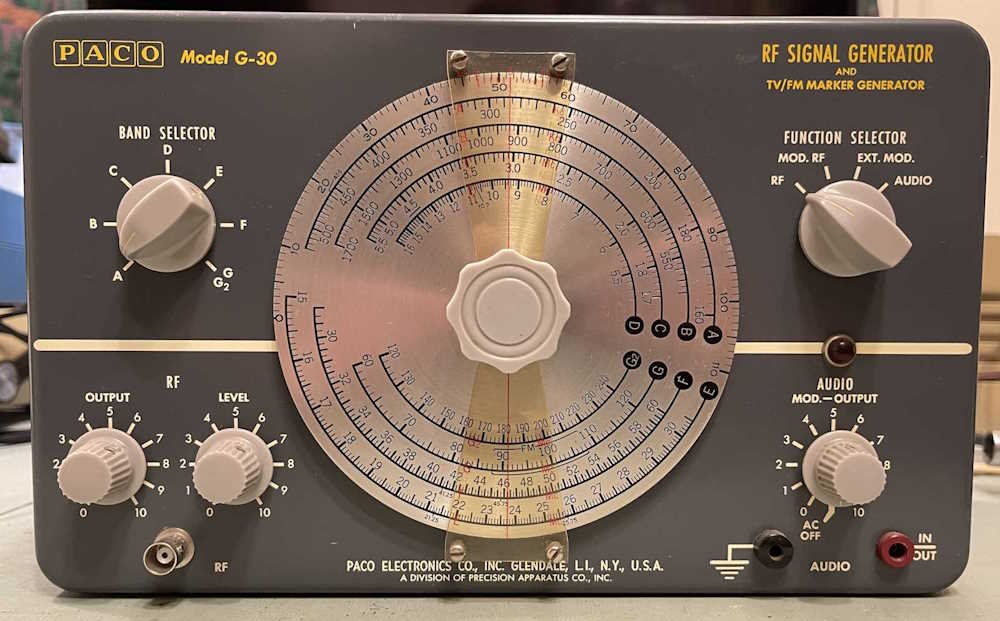
Now that the PACO G-30 is working, and is probably in a bit better shape than it was than before I purchased it, it’s time to take a look back on what happened with it.
Analysis and wrap-up.
When I purchased the unit at Findlay 2022, it was sold working. And it was - mostly. I didn’t check the audio portion, but the RF worked fine. The previous owner had removed some of the old capacitors and replaced a few of the carbon composite resistors. He hadn’t replaced them all as they were well within tolerance - surprising for high-value CC resistors. He had replaced the filters with a strange array of electrolytics. But what hadn’t been replaced was the across-the-line capacitors, as well as the selenium rectifier.
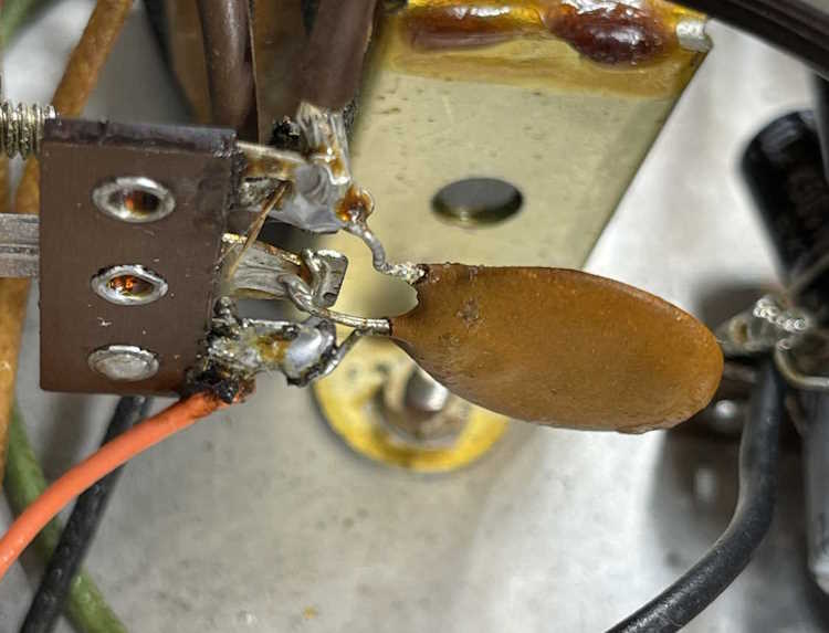
The across-the-line cap was of the three-leg type, a device that has two units back to back with a common leg. They’re well known for blowing apart, and that this one hadn’t done so was surprising. The other device was the original selenium rectifier.
Selenium devices were a stop-gap measure between vacuum rectifiers and silicon rectifiers. They worked fine when new, but as they age the forward voltage drop of the device increases. This happens used or unused. Get enough resistance there, you get more voltage drop, more drop means more heat, more heat means that eventually you’re going to wind up with a device that burns open and releases a lot of toxic smoke into your space. You don’t want that, so replacing it is mandatory. Sure, it’s probably still going to work (for a while,) but it’s a case of when, not if it goes bad.
For the most part, this was just a replace the parts that are known to go bad (mostly done,) replace the carbon resistors because they will eventually go bad (mostly done,) and fix some of the issues left by the previous owner. The across-the-line capacitor was easy enough to replace with modern safety caps, and the old line cord was replaced with a new polarized cord.
As stated, the selenium rectifier is a part that was destined to fail from birth. It needs to be replaced, and for a small rectifier like the one in this device, it’s easy to replace with a 1N4007 silicon. I used this type because I have them on hand, but you could use any diode that exceeds the miniscule current rating, and at least 200V. (You should go higher than this for safety margins.)
There are some considerations to look at here. You’ll need to remember that the silicon rectifier drops much less voltage than a selenium, so some sort of dropping resistor will be needed. There was already a 2.2kΩ resistor in the power supply circuit between the two filter capacitors, so changing that was easy. You’ll need to make sure to measure the current to do some basic calculations and see what you need to raise that value to, but in this case I already knew ~3.3kΩ would work as others have taken the time to do the calcs.
Another consideration you’ll need to make is that full peak voltage of the line will appear on the capacitors until the set is warm and drawing current. Therefore, any capacitors you use will need to handle at least this voltage. The old ones may not have been rated for this, but those old paper capacitors could handle surges much better than modern stuff. Modern parts are easier to get with higher voltages, so don’t be afraid to use 300WVDC or 450WVDC capacitors here.
Resistors are the last consideration you need to look at. Remember that you’re working with higher voltages than a battery device - you need resistors rated for at least your maximum B+ voltage, be it the rectified voltage or the Peak voltage that you see on the filters. Most resistors are rated for at least 300WVDC these days, so you’re good for this device - but if you’re working with 400, 800, or higher - your resistors need to be rated for this higher voltage. In carbon resistors, you’ll see ones that are longer than normal and that gives you a clear indication that it’s a high voltage part. Modern parts give you no such indication, so buy your parts from a reputable house.
Resistors also have to be rated for your surge currents. Carbon resistors can handle surges, and that’s especially important here where you have full voltage on your circuit at the start. Rate it small, and your metal film resistor is a fuse. Don’t be afraid to step up the power rating on resistors in power supplies and other areas where you’re going to be supplying current and voltage to the rest of the system.
What did I specifically run into?
First - I forgot how selenium rectifiers work in a vacuum circuit. It’s been far too long since I’ve seen this type of device, so it took some remembering.
When I first turned on the set, I had a 150WVDC capacitor after the dropping resistor. As the entire of the peak line voltage appeared here (180VDC) I went crap and turned it off. It took a while to remember that the rest of the set isn’t hot and wanting current, so the voltage drops in the power supply aren’t there yet. A quick swap with a 450WVDC part and a bit of waiting, and B+ dropped right back to where it should be, which is ~110VDC.
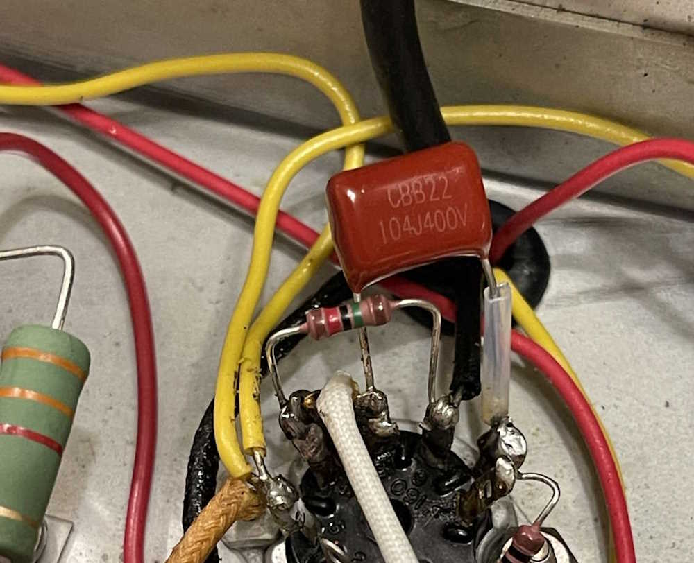
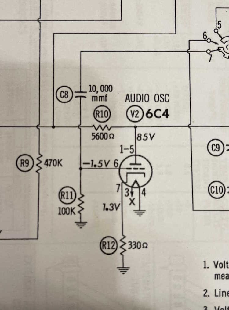
Second - I didn’t have any audio on the audio side. This turned out to be a part the previous owner installed. The grid of the audio oscillator was supposed to have a 100kΩ resistor, The previous owner had a 15kΩ resistor here, which is what I replaced it with as I replaced each component individually with it’s modern equivalent. Once I put the proper value in the circuit and a new tube (the old one didn’t seem to work well) it came right up. It’s a bit off in frequency, but it’s not really of importance as it’s there for you to hear, not compare to the sounds of nature.
This unit is a good example of why you examine devices closely when you’re working with them - especially when someone else has been in there first. A schematic is essential for this, so make sure you have all your docs in order.
That’s about all - other than the wrong part leftover from the former owner, this was a simple “bring it into the modern age” device. Next up is probably an Eico 24x VTVM, but it’s also another “just needs resistors” device. It just needs a lot of resistors as the divider ladders in the measurement circuit are all out of tolerance. Stay tuned!
I picked this little gadget up at the ACARA hamfest. Not because I plan on using it, but because it’s an unusual little thing and had a brand new book with it.
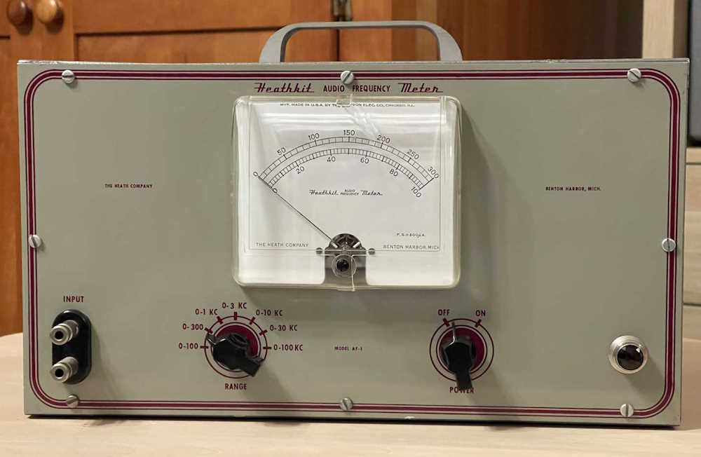
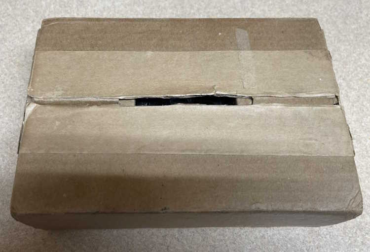
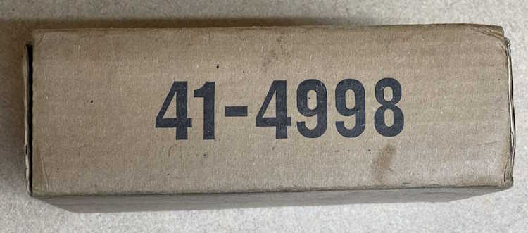
It’s a rather unassuming box with a number on the side.
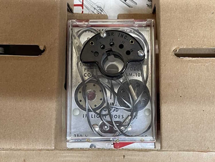
What’s inside is this little gadget, a power cord, and a book. The gadget:
It claims to be a Tricraft Products Corp SM-101 Filament Checker. I’m not sure how it works because there’s no instructions for the device. It appears to be used, but only very little. I can see some wiping on the contacts. The power cord was unrolled and rolled back up with bread ties.
I can’t imagine this was terribly useful, your VOM would have been quicker than getting out a power cord and plugging all kinds of little pins together in an attempt see if the filament was good.
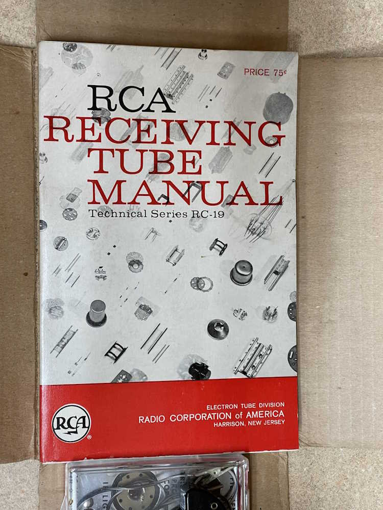
The real gem is the book. The RCA Tube Manual RC-19 from 1959. It appears to be unused, if a little dirty.
That’s worth the few dollars I paid for it right there. The other piece? A cool gimmick gadget for display.
I’ve discovered the audio side of this unit doesn’t work. When you get a device like this, you can assume one of three things (and this applies to the state this device was in when received.)
1: There’s something wrong, i.e. something is broken.
2: You put a part in wrong, or made a mistake in replacing parts.
3: The previous owner did something wrong, and you followed in his (incorrect) footsteps.
I started this by checking the plate and grid voltages.
A word about this device: I can’t seem to figure out where they measured from here - Chassis is ground, but the device also is raised about 8V above ground to provide a negative voltage. Some measurements seem to be from chassis, some from raised ground (return). I wasn’t able to get some of the marked voltages, so…who knows. Bob from Accounting probably drew the schematic for this at lunch so it’s possible something isn’t exactly right.
Regardless, B+ was correct on the 6C4 audio oscillator. Grid was not, so ah-ha, there’s my problem. Well..not necessarily in this case because you could go to return and get a different voltage for each measurement. But in this case, it was the problem.
I discovered this because I looked at each part I took out and did a like-for-like comparison with what I put in. Everything matched. The problem became apparent once I really started looking at the schematic.
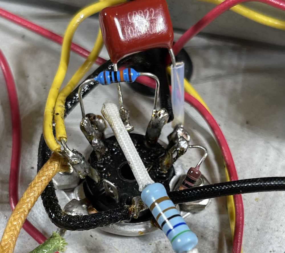
So, you’ll notice there’s a 15KΩ resistor coming from Pin 6 of the 6C4. That’s what the previous owner had in there.
The schematic, however, states that we need a 100kΩ resistor:
That’s probably the problem. I had some 100kΩ left from one of the previous rebuilds, where I wisely just bought a bunch. One of those goes in:
It still didn’t work, so I grabbed the tube from a parts unit I got at Columbus…
And, there’s our audio.
It’s 500Hz instead of 400Hz, but who cares. It’s still going to be heard just fine. The bad grid resistor destroyed the original tube, but…oh well.
Since the device is now working, it’s time to button up for the wrapup post. Stay tuned!
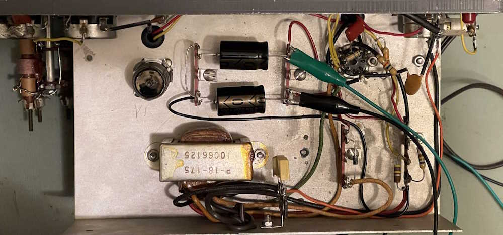
After confirming the power supply was operational (and remembering how that works!) I started in on the resistors.
Some had been replaced before I received the unit (foreshadowing!) and some were original. It was a mix of modern film, old film and old carbon comp resistors. I have to wonder if these were the special military units, as the remaining carbon comp parts were well within tolerance. Considering I’ve seen multiple of this particular device and every one of them has a different style of parts inside, it’s hard to tell.
I decided to just do them one at a time. Unsolder, remove, and replace with the same value. At least, the same value as what’s in the unit now.
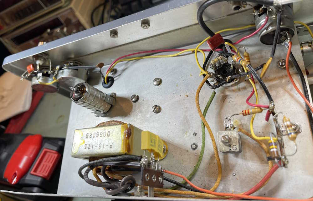
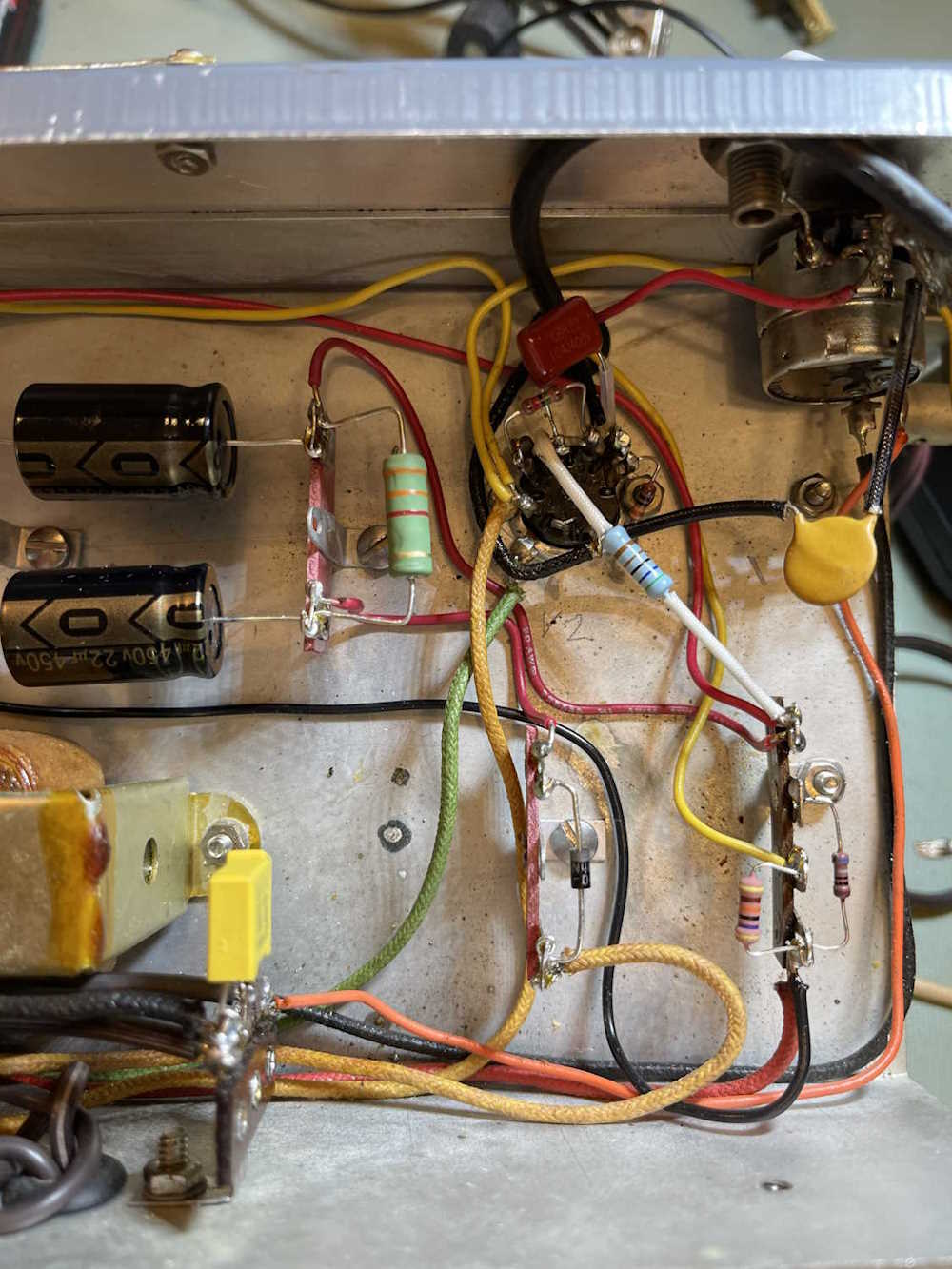
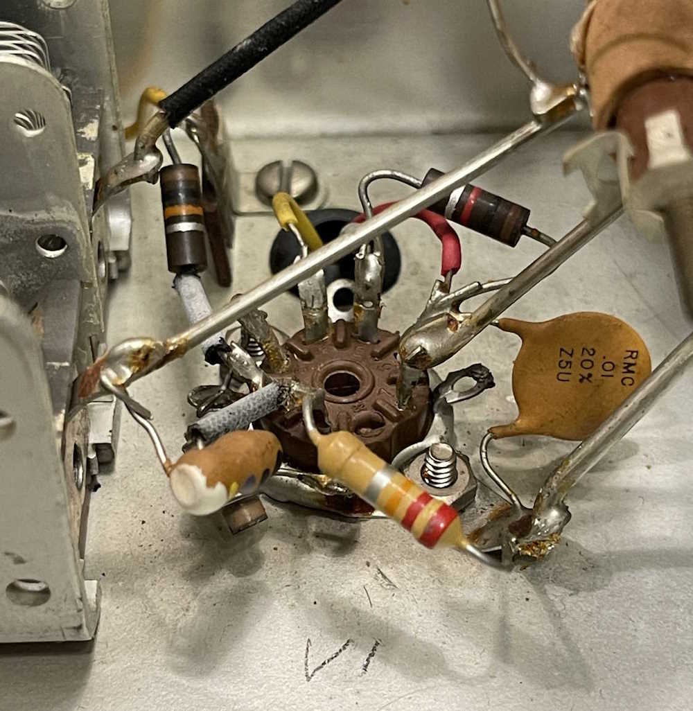
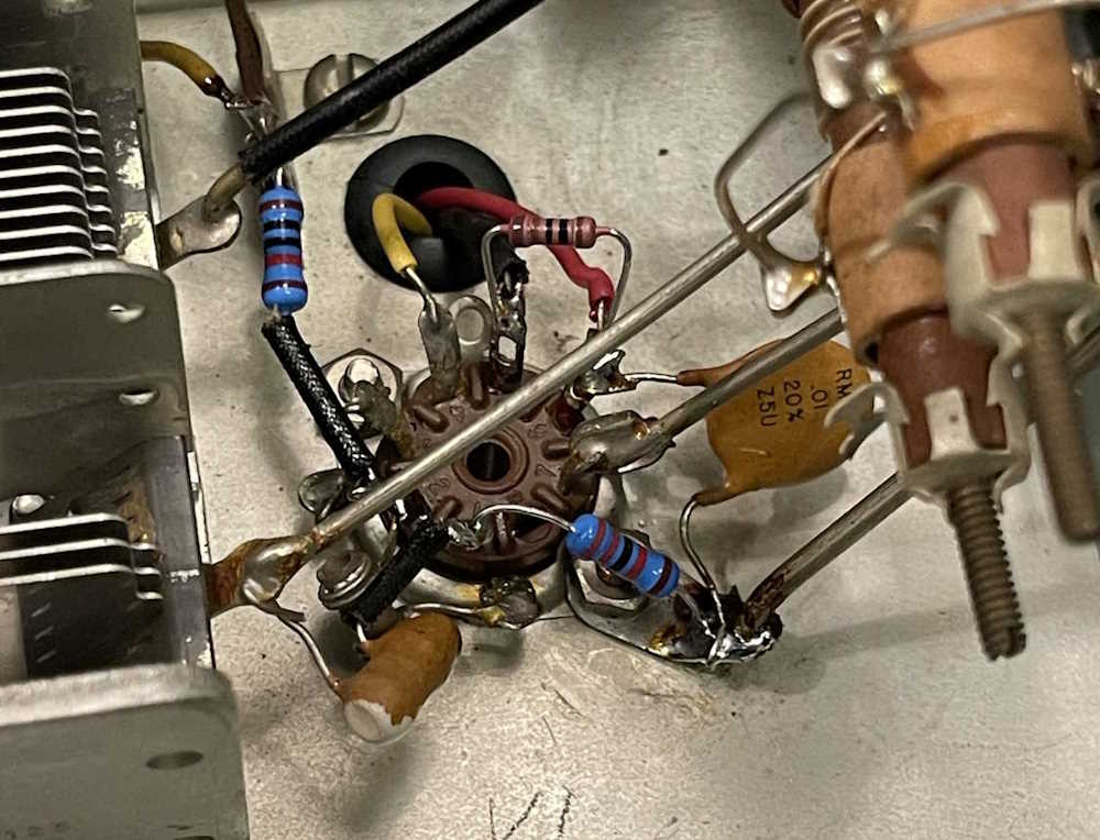
Here’s the bottom after replacing the resistors, diode, and capacitors (yay bad lighting!)
This is what the top looked like before replacement:
And after:
After a quick inspection, I fire it up. RF looks good - for the given value of good this device offers. The audio side? Not so much, there’s nothing there. Uh oh…stay tuned for troubleshooting.
This was my first time attending this event. It was an easy drive, so I decided why not? This took place at the Athens Community Center in Athens, OH, and featured about two dozen vendors in a sheltered parking area as well as a couple in the center itself.
This one had a different selection of gear, with more test equipment and consumer gear appearing to show up at this one. Of course, a handful from TUSCO were also here, so I saw some of the same stuff (but didn’t photograph it as you and I have already seen it!)
As with the other shows this year, I’ve noted that prices are trending upwards, especially on those things that are considered cachet - Simpson 260 devices and tube testers are commanding higher prices again, even if they’re a bog-standard bottom of the barrel emissions tester. Dayton will be the tell on this one, if prices there are back to normal we know the economy is doing better.
Here’s what I saw at the show:
CD-R…once a miracle, now just junque.
The camera doesn't do the chrome justice.
An interesting passthrough counter.
A desoldering iron from the tube socket era.
An all-in-one RF test station.
Some older test gear including a cap checker in the box.
An HP 200 series generator and an old tape player.
A “Portable” multimeter.
Once of those tube unit power supplies.
An old Sony reel-to-reel tape player.
A couple of scopes. Interesting, but not needed.
An interesting Sencore tube tester.
Radios and an overpriced PACO tube tester.
A bad shot of some old gear. Would have taken the rightmost one if it had been in better shape.
One of Trio's active panel meters.
One of Heathkit's interesting lunchbox tube testers.
Some radio tuning gear.
.
As I wandered through the show, I overheard someone saying that he’s not going back to Dayton because it’s held at Xenia now. “HARA was a dump but it was my dump! and I don’t like Xenia.” I had to lol, ok dude - I appreciate being able to walk through the parking lot and not twist my ankles, so you can stay away and I’ll buy the junk. HARA was certainly a dump, and I don’t miss the burnt mystery burgers and the dimestore nachos.
Speaking of Dayton, the Hamvention (as of this writing) is only about 3 weeks away. I’ll certainly see you there, but if you can’t attend then come back for pictures shortly after.
This is a small show at the Tuscarawas County fairgrounds in Dover, Ohio. I’ve been attending since 2023, when they reopened after the country decided that they needed to not do anything for a few years.
This show seems to attract a decent crowd of vendors, and a decent crowd of attendees. I took home a few books and odds ‘n ends from this one, which is exactly what I expected.
Some interesting equipment. Radio gear?
Lots of vidicon tubes. Lots and lots and lots!
The early 80s still live among us.
A dual band (lol!) Lafayette Radio.
I bet you never thought you'd see more radios.
AM/FM/8-Track with a cool honeycomb face.
Radio Shack ghosts haunt us.
A couple of old Tek (tube-type) scopes. Ok price.
A mini scope. That seems high priced.
Just stuff from the CFARC guys. I took the decade box.
.
Prices generally seem to be heading North this year, so get it while the getting is good. I did see some things that were not very reasonably priced - they would have been fine 10 years ago, but with technology changes things that were portable then are obsolete now.
Not a whole lot else to say about this one, so enjoy the photos - ACARA’s photos are coming up next.
First things first, this device needs it’s input and power supply corrected. This involves adding a new polarized power cord, replacing the across-the-line capacitor, and replacing the selenium rectifier and capacitors with a silicon diode and new capacitors.
The across-the-line capacitor is two capacitors back to back, with a common leg.
It’s really amazing that this thing isn’t cracked in half. Two new safety capacitors will go in it’s place.
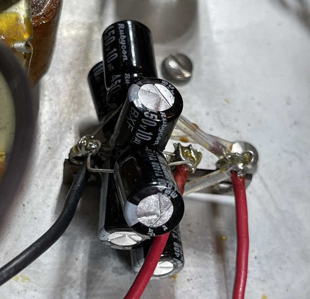
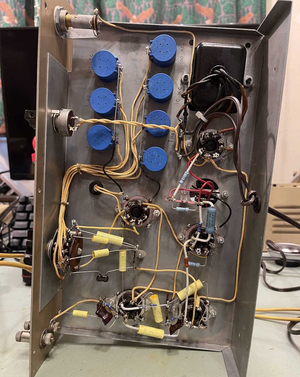
The unit had new capacitors installed by the former owner, but I didn’t like they way they looked.
I understand the person probably used what they had on hand, but still. This is kind of sloppy, but it worked. Note that the capacitors are 450WVDC…
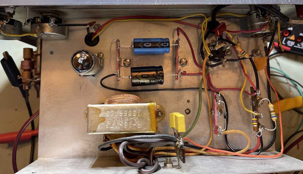
The first thing to do here is start removing parts. I’m going to use the screw for the tuning capacitor to hold a new terminal strip, and put a new hole in for a second, so I can string the new capacitors out a bit. This also gives me room to add a new dropping resistor, since I have to account for the voltage drop of the selenium diode. The old safety capacitor was removed, as was the old line cord.
All of the new parts were added in save for the dropping resistor in-between the two capacitors. I intentionally left that out just in case I needed to experiment. I’ve seen others doing this same task, and they’ve come up with a 3.3kΩ resistor, so I decided to start with that.
Regarding the dropping resistor: You’ll note that the original was a carbon comp part rated for 1/2W. While I’m going to more modern oxide and film resistors, I stepped the power rating up. Why?
CC resistors had the ability to withstand a good current surge, especially if it was quick. Modern film resistors do not have this ability, and can act like a fuse - especially in circuits like this where capacitors are going to be charged immediately when the set is turned on. You get that small surge of current, and that can destroy things. Since modern parts are smaller for the rated values, I chose a relatively inexpensive 5W oxide part for this section.
After removing all parts and installing their replacements, I set up for some testing:
I used a 47μF in place of one of the capacitors, mostly because the previous owner put 30μF in for both sides of the filter. It’s not that much of a stretch to go from 20μF to 50μF, especially with a modern diode in there, and the effect of the dropping resistor limiting current at startup.
After a quick wiring check (make sure those wires from the transformer are correct, the red color on the red/yellow line has long since faded to nothing!) I clipped the resistor in, and applied power.
B+ was 180VDC.
On a 150WVDC capacitor. Whoops. Turn it off. What went wrong here? Well, it was staring me in the face, but I did a test with the original selenium rectifier. Same thing, only about 170VDC. The selenium obviously had a voltage drop, but it wasn’t enough. What was going on here - the original parts were only rated for 150WVDC.
I think I know what’s going on here, and it’s related to the rectifier type of the circuit. A solid-state device performs differently than a tube device, and the OEM took advantage of old part characteristics when designing the unit. I changed the 47μF with another 22μF @ 450WVDC part, applied power, and…
Upon powering the unit, the B+ went to 180VDC - and then dropped as the tubes warmed up and started conducting. Just as expected, once the circuit was operating the B+ fell right in line at 109.1VDC (s/b 110) with an input of 120VAC.
So why did this happen? In a pure tube circuit, where the rectifier is also vacuum, you have a circuit that warms up together. That is, the full B+ probably won’t be available until the rectifier is hot - by that time, everything else is hot and wanting current, so you have a proper load.
A selenium circuit, however, has B+ available the minute you turn the set on, as the selenium stack is essentially a primitive semiconductor diode. You’ll have full line (120 * 1.414 - Vf) peak there - until the rest of the circuit is hot and wanting current. Only then do you have the proper loads and can expect B+ to be the nominal value.
But the original part was only 150WVDC! Yes, and that’s because those old paper capacitors could handle surge voltages for a short time, and they didn’t care. Sure, it may have shortened the life some, but 20 years later it’s dry as a bone anyway, who cares. You need to rate your parts for the full peak voltage you’ll see on the device! A 250WVDC part would have been fine here, but I have 450WVDC parts - so in they go.
I can always add more capacitance if there’s an issue, but it’s back to where the OEM had it.
So, that’s on me. I forgot things I learned 35 years ago and never used until today. But now I know, and if I (or you!) run into a selenium powered circuit that you want to retrofit, you have a better idea of what to expect.
Next is resistors. While some have been changed, and everything else is right on tolerance, I’m going to replace them anyway because they’re almost all carbon comp resistors. I was only planning on changing a few, but there’s no need to leave the old ones in there - resistors are cheap, and making this thing ready for it’s next 50 years is what I’m trying to do here. I have a few on order, as soon as they get here I’ll solder the dropping resistor into place and get started on replacing other parts.
The first is the TUSCO Amateur Radio Club hamfest at the Tuscarawas county fairgrounds in Dover, OH. This is a small show, and usually is good for an hour of wandering and looking at everything thrice. I’ve been attending this one for a few years, and there’s always a trinket or doodad that comes home with me.
The second is the ACARA Athens Hamfest in Athens, OH at the Athens Community Center. I’ve never been to this one, but it’s close enough that I’ll check it out just to see what’s there. It may become part of my regular show schedule.
TUSCO ARC Hamfest
Commercial Building at the Tuscarawas County Fairgrounds
295 South Tuscarawas Ave
Dover, OH 44622
April 26
8A - 1PM
https://www.w8zx.net/hamfest
ACARA Athens Hamfest
Athens Community Center
701 E State Street
Athens, OH 45701
April 27
8A - 12P
https://www.ac-ara.org/
This was an interesting device - not in the circuitry, as there was nothing in here that’s really unusual, but in the device itself. This was sort of a “because we can” device that was rapidly made obsolete by changing technology, and something that would have been difficult to calibrate without some sort of advanced tech. Regardless, it’s a rather unique piece that I’m happy to have in my collection.
What is there really to say about this device? Not much. It was a straightforward rebuild, and other than finding an actual schematic for the device, presented no issues other than the mystery of the potentiometers. That was apparently noticed by the original builder as well, seeing as how they had been changed for parts that were far in excess of the specified values.
I’ve been talking to some people about this device since completion. One of the interesting facts I’ve found out about this is the European version was sometimes branded Daytrom - pretty wild, considering both the fact that Heathkit was “A division of Daystrom, Inc.,” and also the Star Trek implications of that name. I also found out that they tended to use miniature tubes instead of octals. I’ve been told (via FOAF) that tubes tended to be less common in Europe as opposed to the USA. That’s not to say they aren’t readily available, just that we in the USA made millions of the things for the war effort, and they’re still available. Quite cool, and I’d love to get my hands on a piece of Daystrom branded equipment.
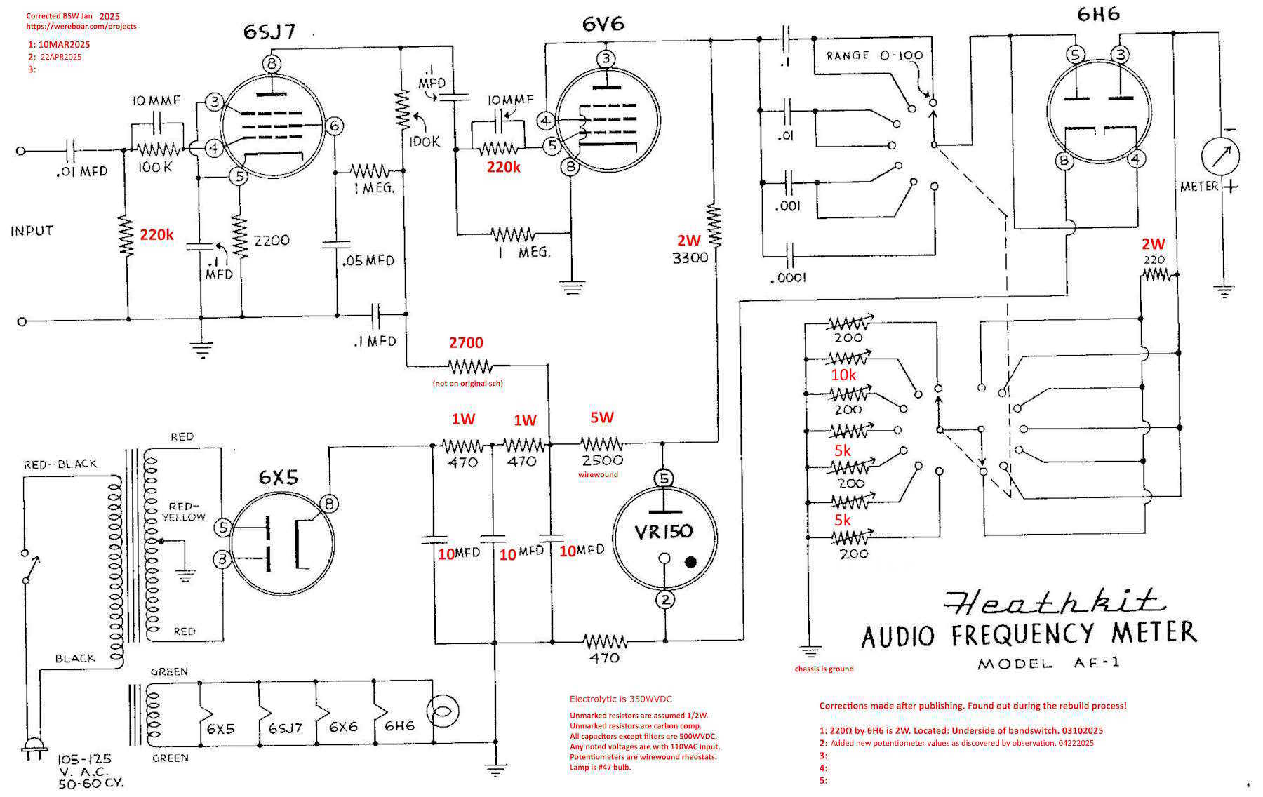
A note on the schematics: Heathkit published a book of devices with schematics, and this is where the one you’ll find online came from. It’s a pre-print, and is wrong. If you have one of these, you’re well served by going to ManualMan and getting the manual for the device. But if you can’t get that, here’s what I found during the rebuild:
That’s about it. The device itself has a display spot on the shelves, but it’s not necessarily the most useful thing - especially considering that I used a modern counter to align it! But still, it’s a piece that reminds us that technology changes, often times quite rapidly.
The only part I changed the value of (from the original builder’s parts) was the 300Hz potentiometer. It needed just a little more range to dial it in. Why does it need this? The original schematic shows 200Ω parts for all sections.
The filters being used here are passive high-pass filters with a vacuum diode pair in the middle that both rectifies the signal in a half-wave configuration, as well as provides a small lift above ground so the unit isn’t triggered by transient noises. The potentiometers are the R component of the CR filter, so adjusting the pot changes the cutoff point of the filter. The filters aren’t very sharp to start with, and the diode and pulse waveform we have at that point doesn’t help much.
I really need to sit down with this thing and a scope and see what’s going on, because pure calculations don’t really add up to what I observe.
That leads us to testing. I’m not going to do a full characterization of this unit, because this has turned into more of a labor of love rather than me rebuilding somethig that’s going to sit on the bench. The device is just cool, it’s unique among test equipment, but it’s not terribly useful. Read on for more on that.
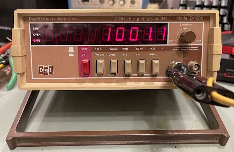
But, for this test, I’m going to be using my good ovenized counter,
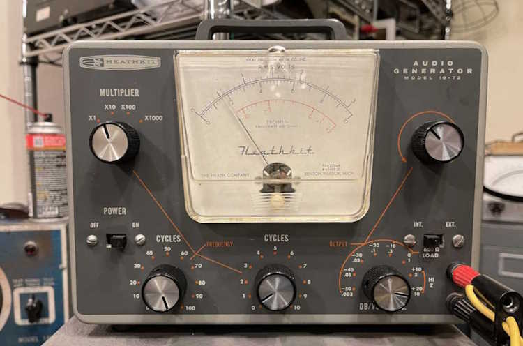
as well as the Heathkit IG-72 I picked up at a show last year.
The IG-72 needed some minor repair before use, the potentiometers had become sticky and the signal had started to clip again. A quick cleaning and re-adjust brought that back where it should be.
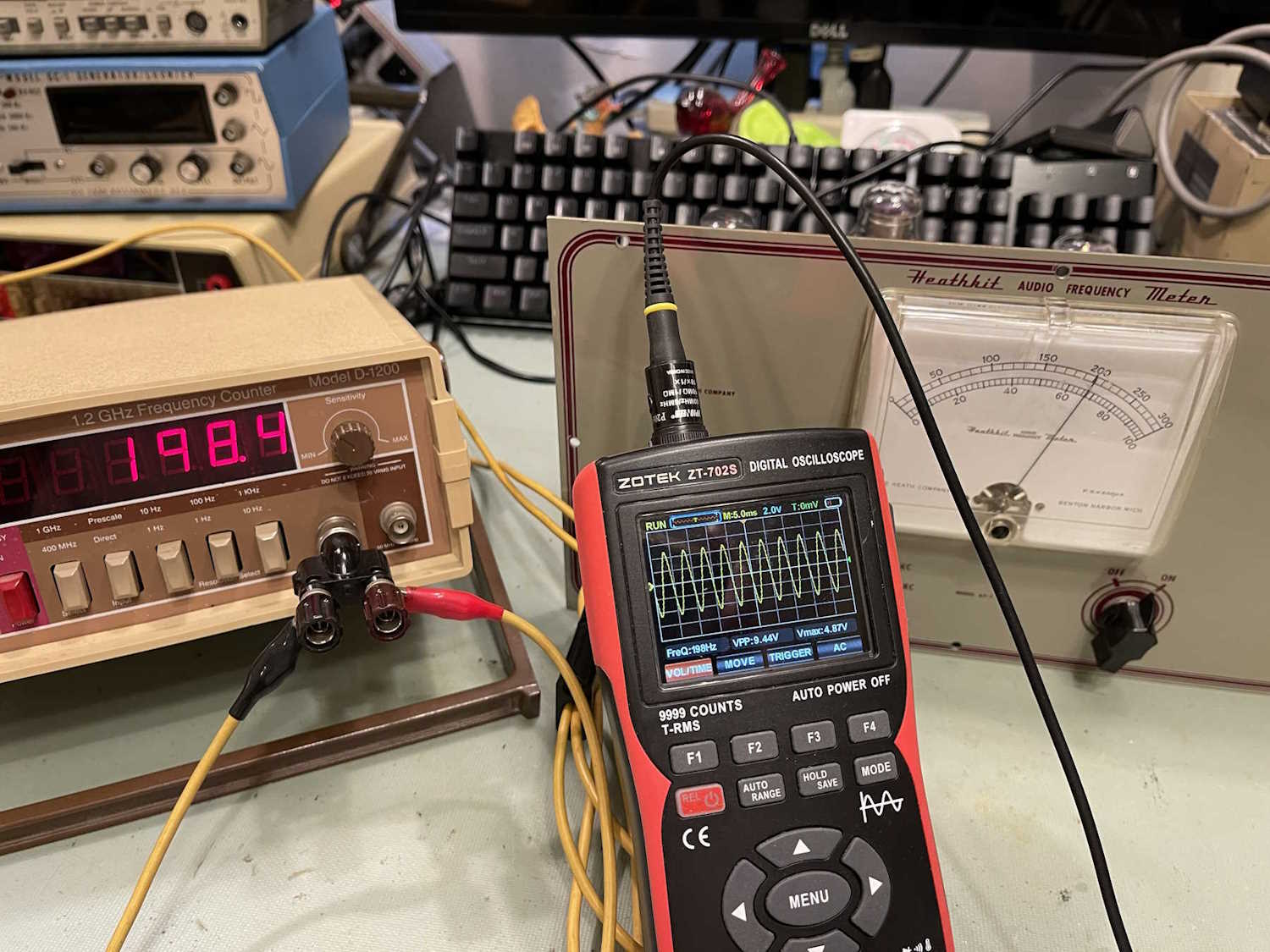
Calibrating involved letting the device fully warm up, and selecting a frequency to calibrate. Since these are all high-pass filters, the device probably works best in the upper part of the band, and Heathkit confirmed that in the manual by telling us to select our calibration frequencies in that range - for example, it suggests calibrating the 100Hz band by picking up the 60Hz on the pilot lamp.
I have better equipment, so I chose 70 and 200, multiplied by band scale. The executive level summary for accuracy once the point was dialed in:
100Hz - Good
300Hz - Good
1kHz - Good
3kHz - Good
10kHz - Good
30kHz - Acceptable
100kHz - Marginal
So…does it work? Yes. It’s pretty stable. But that’s for a given value of “Does it work.”
I have some thoughts about this device and will publish them in a wrap-up post. Stay tuned!


 Lafayette Radio.")


 scopes. Ok price.")