Revisiting an old project with new ideas.
Wednesday, April 27, 2022 at 09:23:34
A few years ago, I wanted to create a device to measure the current being consumed in my home. This isn’t a particularly new idea, especially with rising energy prices - having some sort of feedback on what you’re doing can help reduce unecessary useage.
There are a number of devices and systems out there that already do this, including some that can access the information from an electronic meter connected to the mains supply of a house. These are meant for Joe and Jane Average, and often rely on proprietary backends to do their work and don’t expose any kind of data that can be placed into a historian. If they do expose data, then again, you’re relying on someone else’s computer and your internet connection to provide said data, and those systems may change or go away at any time.
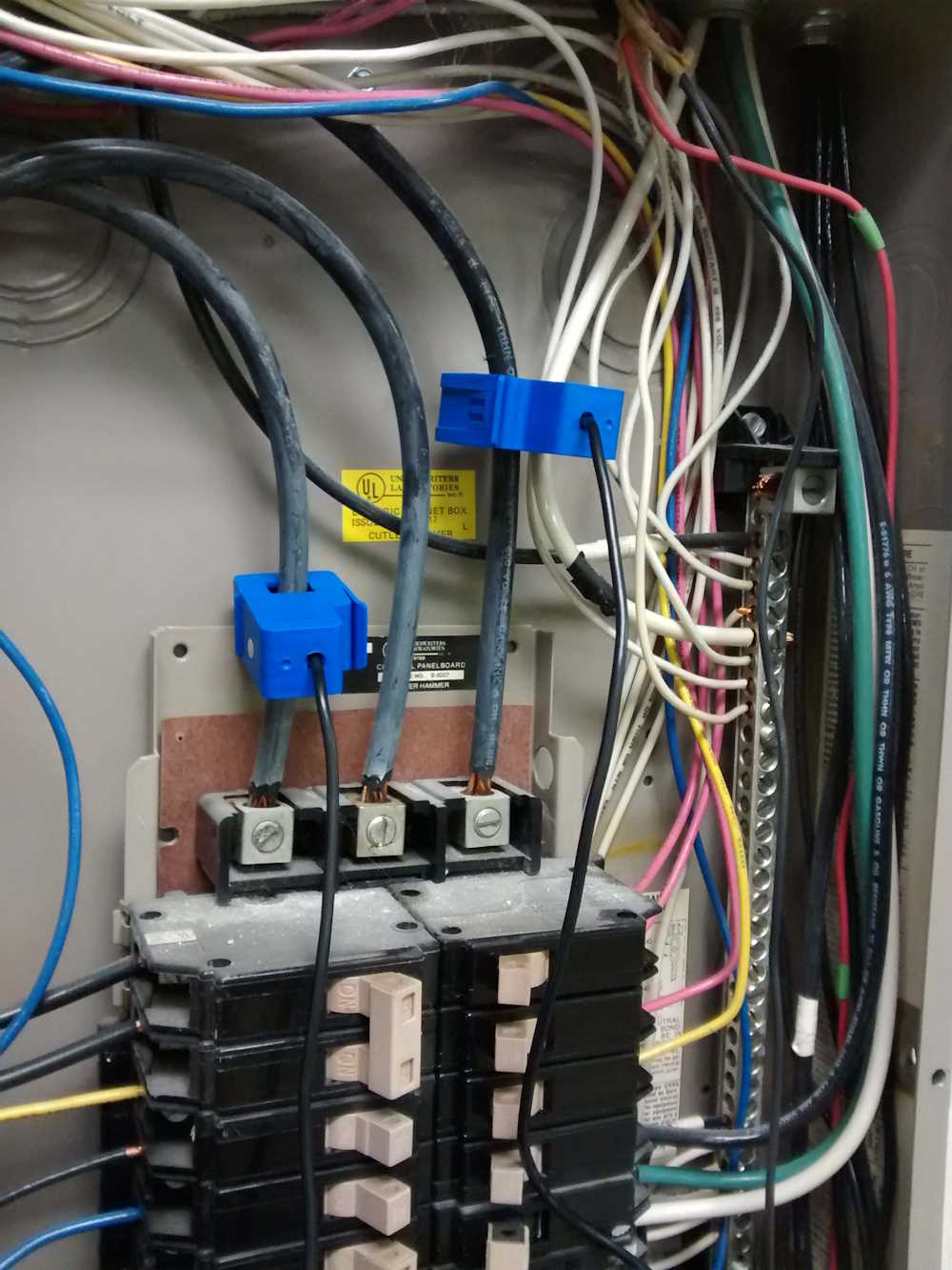
The goal, then, was to create something that could provide a universal data output that could be connected to any device capable of reading said output. An analog voltage from an analog circuit was chosen, both due to the instantaneous response, the the availability of cheap current transformers, such as the one in this picture. This device simply snaps around an incoming AC line, and provides a physically isolated output of either (in this case) current, or voltage.
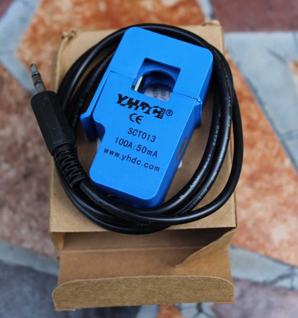
This solves the biggest problem of how to get the measured current out of the fusebox without cutting AC lines. I’ve chosen voltage output devices for this particular project, and since the voltage output is small (usually in the mV range for full scale,) the first thing to do is amplify it a bit. This is accomplished with a standard op-amp circuit with a gain of 10-20, depending on the current transformer chosen. This also gives a bit of isolation, but that’s not really necessary at this point.
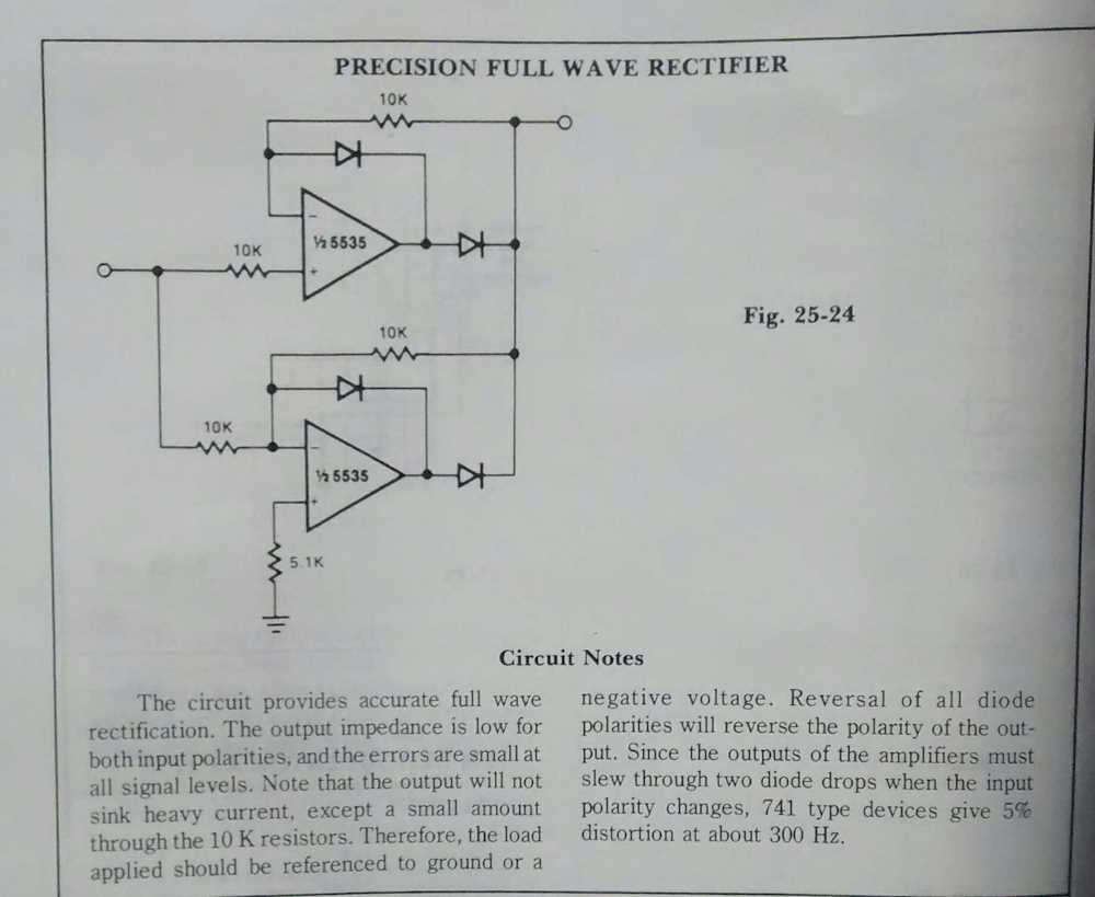
Next is how to feed this into something that a hobbyist would have access to. Measuring DC is much easier than measuring AC with commonly available microcontrollers, so the problem to solve is converting this signal to DC. This can be done with a simple bridge rectifier circuit, but I prefer to use something I found years ago in one of those “Big Books of Circuits” that TAB Books used to publish. The circuit in question is called a precision rectifier circuit, and the goal is to output a signal similar to the input, while minimizing losses. It works well enough, and a small capacitor and resistor on the output gives a decently filtered DC signal with fast-enough response.
While I’ve built this circuit on bread- and protoboards many times, I decided to lay this one out on a board.

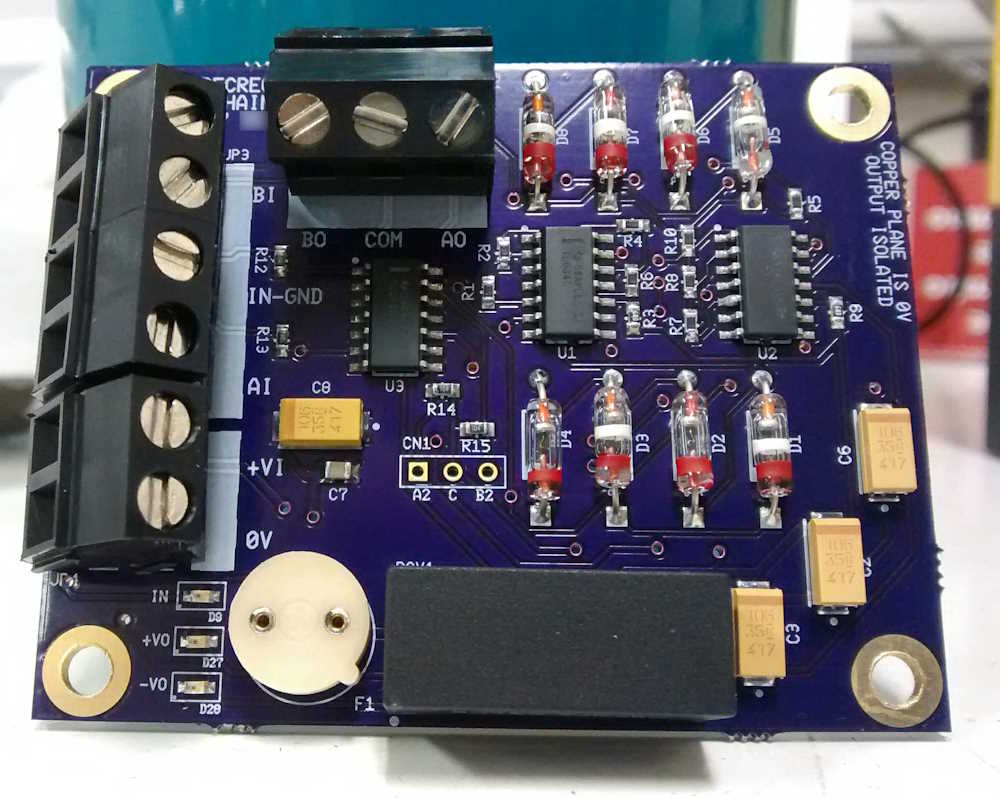
The board turned out ok, but now that I have more experience with layout, I’m not really happy with it. But it works, and all of the germanium glass diodes used as rectifiers provide a rather cool look. I’m going to go with shottky diodes for the next round, simply because germaniums are getting harder to find and the shottkys are better at handling even the low slew rate of a 60Hz signal.
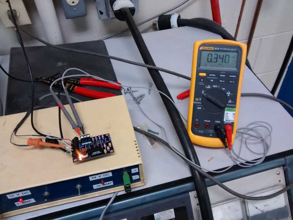
Two remaining tasks at the time were to test the board and it’s output, and to choose a microcontroller platform. Testing was easy, the project had originally found a home at a former employer as a monitor for air compressors - the company wanted to run tests over the weekend requiring compressed air, but needed to know if the compressors were to become locked in an on state (which would subsequently result in overheating and damage.) I did the initial testing in the fusebox for the compressors, and was able to translate the resulting DC output into a correct current draw. The employer then lost interest as it was revealed this was going to cost more than nothing to fully develop. I had to abandon the project as the business slowed and let people go while the sky was falling.
For the next round, I’m planning on trying out some of the new microcontroller options on the market, especially the Raspberry Pi Pico. This is a fast, dual-core Arduino-like that’s extremely inexpensive, and has an Ethernet onboard option offered by a third party. My original design choice was to use an ESP8266, but that didn’t go well, so was abandoned. Read this entry for my misadventures with the ESP controllers: https://pygg.xyz/pro … of-cheap-technology/. A new board with multiple channels of input is in the works, and will offer a better onboard ADC as well as some user amenities like a display. Stay tuned for the next update!
(Future me update: There are plenty of zigbee devices that do this now, I’m no longer pursing my own solution.)