- 2023
- Mar
- 19
The TMRA Hamfest Haul
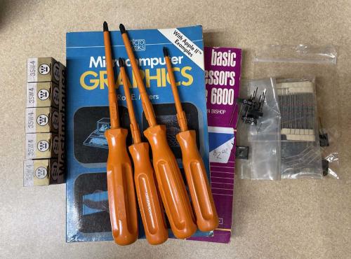
I was kind of disappointed, nothing really stuck out at me and I didn’t see anything picture worthy. The only real item, other than some parts, was a nice old Hickock DVM with VFD tubes, but someone picked it up and put it on their own table for resale (at a higher price of course.) I don’t need another meter but eh…
I don’t know if it’s because of the area, because what I’m looking for didn’t show up, or because there didn’t seem to be as much general electronics as I’d expect, I only came home with trinkets.
A sleeve of 35W4, because you always need more of those, a couple of books, some insulated drivers, and some parts are all I took home. There are more shows coming up, so we’ll see what happens.
- 2023
- Mar
- 19
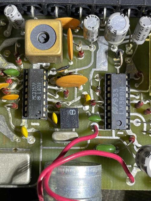
Random board shot - a commercial weather radio.
It’s always interesting to open a device and see ancient chips you’ve never run across before. The LM389 is a LM386 with three transistors for RF, IF, and 2nd IF on the substrate. This ancient commercial weather radio uses one for it’s audio final, if I want to keep it in operation it’s probably best to find a couple of spares along with the MC3357 IF chip next door. This device was made in the USA, even the circuit board was made right here in Ohio as evidenced by the GE Textolite “T” in the substrate of the board.
It’s well built, but the electrolytic capacitors with the long leads surprise me. I would think for a device with RF floating around inside, you’d want to keep those short.
It needs a new power cord, the old one is short and worn, as well as some DeOxit sprayed in the controls and switches. I may also replace the power supply filter capacitor, but that’s only because it was laying against the regulator for untold years and has a nice discolored spot on it.
- 2023
- Mar
- 12
A General Electric T-125A “All American Five” Radio, Part III
This is part 3, and the final part of working with this radio. It didn’t turn out as good as I’d hoped, some of the other capacitors are leaky - and some of those are in a couplet. The customer just wanted it to make voices come from the air, so I’ve left it at that for now.
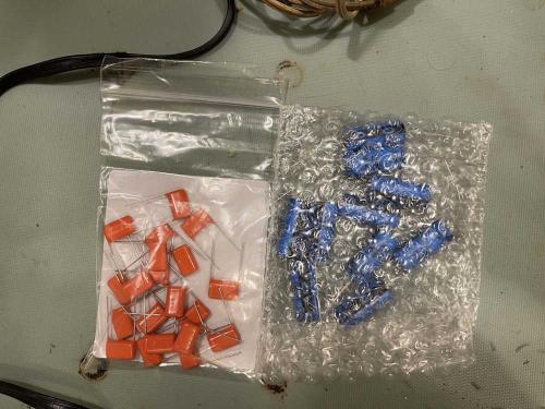
The original diagnosis I came up with was bad filters, and that was the case. The original electrolytic capacitors were bad, and were simply acting as opens instead of capacitors. The device in questions was a dual section, wax sealed tubular device, consisting of a 50uF and a 30uF part. I chose to replace them with Cornell-Dublier 47uF capacitors, which should be good for another 50 years. The across-the-line capacitor also got replaced with a Vishay 0.047uF @ 600VDC device. Just as good as the original without the bumblebomb problems.
The parts, fresh from Mouser:
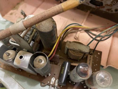
What we’re working with. The black tubular part in front, and the metal cased tube in back are the suspects. If you look in the middle of the board, you’ll see a reddish-brown rectangle That’s the couplet, and was a cost-saving multi-part unit. When they go bad you rebuild what’s in them…
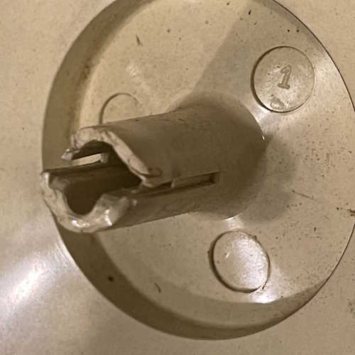
Other problems reared their head as it was being taken apart. The biggest is the age of the plastics. The knob used a metal band on the plastic to tension it on the shaft of the tuning capacitor. Pulling this knob from the shaft left the tension band on the shaft (it had little ears that were probably used during manufacture as an install aid,) and the plastic is so brittle and dried out that it just crumbles to dust. There was enough left to put it back on, so I broke the ears on the band off and replaced the tension band and said “Don’t touch this again” to myself.
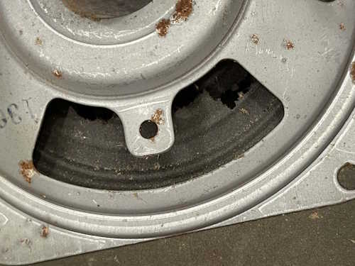
The other bad thing, and something I didn’t notice before, is the speaker had a tear. The paper was so rotten it felt like wet tissue and just kept tearing itself. Well, it still works, and this can be replaced easily enough if desired.
So, on to the repair. It was a simple matter to desolder the parts, the heavy copper on the board let it’s old solder go with a 35W iron and some wick. The parts pulled out easily and the board cleaned up well.

You’ll notice the board is discolored. That’s where the 50C5 power amp tube sits, and it gets toasty. The solder joints are exhibiting potential cracks, so they all got touched up.
The parts I installed were much smaller than their vintage counterparts, so they got bent leads to sit down on the board, and were just placed in the board. I wasn’t going for a beauty contest here, they need to be in there solid and electrically correct. You’ll notice the one electrolytic is offset a bit, I realized after I put one in that the banana slicer had one section larger than the other. Oops…that other part goes in the parts bin.
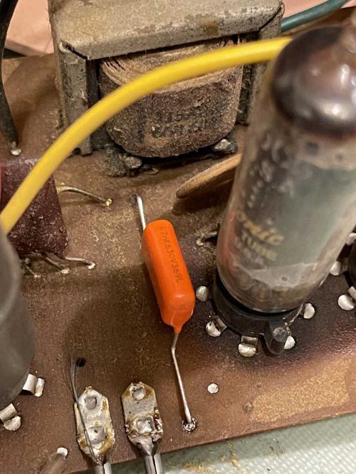
Yes, that’s not really a safety cap. But this device isn’t going to be used. It’s purtyful.
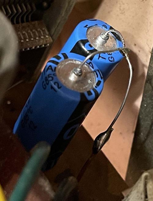
For the filters, I just jumped the two together with a loop, looped a piece of bare wire around the common and soldered it all together. The original capacitor was full of old wax and wasn’t being rebuilt.
It was all back together…but there was still no joy. The filters took care of the buzz, and the output was nice and strong - then it started to fade and get fuzzy as something started leaking. One of the coupling capacitors or other small filters on the plates is probably leaky and drawing things out of tolerance, or a tube is bad. On a whim, I tested a few of the tubes, and they seem ok, so it’s probably one of the capacitors. With some being in that couplet, that’s more of a job that a “I’ll take a look” can cover.
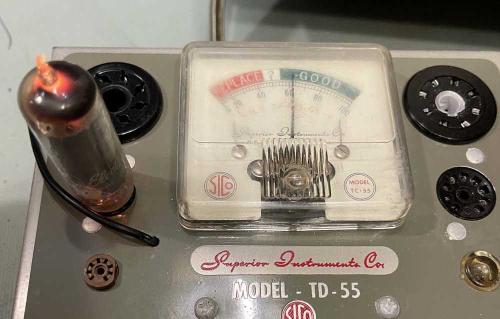
That 50C5 is probably bad, however. They can exhibit exactly what is going on when they get really old and near the end of their lives.
It goes back the owner this week, if they want more repairs that’s a different proposition. Some of the younger members of that family are starting to get into electronics, perhaps this is a good project 15 years down the road.
Beyond that, it’s really not cost-effective to repair something like this for someone else unless they understand it’s basically a replace everything deal.
