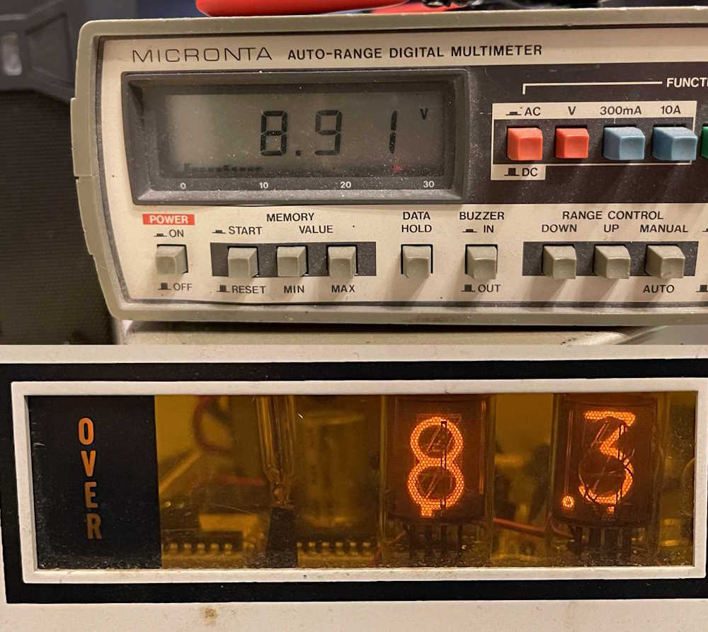
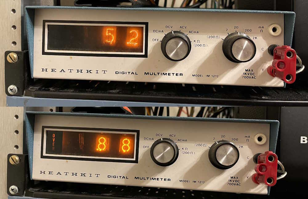
I decided to put the Heathkit IM-1212 meter in operation as a bus voltage monitor for my network rack. It’s currently on the 5V rail, but I’m working on a solution to get it on both the 5 and 12 volt rails.
5.2V is about right, considering it’s something like 5.11V at the distribution board.
The oscillator adjust, which should be 0.85, is already off. That’s about par for one of these.
I have enough time in the industry to comfortably “sit back and reflect on things that have happened over the years,” and one of those things that came up in conversation recently was why I turned down some positions that I applied and worked towards getting.
It took me some time to come up with a reason for this, but I read a short article about the same thing and that described it very well. It helped me put into words what my reasons are - that all of the positions I’ve been offered and turned down were either lateral or downgrades, pay wise.
There are a number that were serious downgrades in pay that just got tossed by the wayside because the company had not been truthful about what was being offered at the start. These places generally had a bad company attitude as well, and it’s probably for the best that they revealed their hand before I took the offer.
There are two that really stick out in my mind, however. One was a company looking for an engineering technician. This person would be entering a “Now apply what you learned” situation. The company offering this knew what I made currently, and knew I would be picking up and moving. I had a good feeling about this one, and assumed that because of the increased skill level required it would be paying accordingly.
“Accordingly” was a number based on some people I knew doing similar work at comparable companies.
They didn’t offer that number, and offered somewhat (not a lot) less than I told them I made currently. I turned it down. I received a call later from the company asking what they could do to make me interested. It’s the money, make me a reasonable offer for an engineering technician. You’re not giving me any reason to be attracted. I know the job is longer hours and more intellectual work, pay for that.
I never received any further contact, so I have to assume that they either went with their second choice or started interviewing again to find someone that would take their offer. I found their HR person on LinkedIn years later and extended a “Can I talk about that?” but never received a contact.
The second was more of a plain lateral move. The company did offer slightly more than I was making at the time (about $0.24 / hr more) but their benefits structure would have eaten up considerably more than that. It would have turned out to be a net negative with a longer drive. Again, the contact asked why I was turning it down.
It’s the money. It may be a bit more gross, but the net is less and you’ve not given me any reason to be attracted to your company - make me a better offer. You know what I said I’d like to see. I’m not leaving this job for that job when I’m not gaining any benefit. You seemed very pleased that I could pass your test and talk shop with you. You want my skills, how about a bit of compensation for them?
That didn’t go anywhere either. I did contact them later when some stuff happened, but they weren’t interested in talking anymore. No big deal there, I understand.
(2025 Me notes: I spoke with a friend about this. He knew people at this company personally. He told me that they had related how they were unhappy that I hadn’t taken the position as I was “their guy.” He told them the same thing I did: It wasn’t enough money, to which the contact replied “Well, that’s what we pay for that position.” It’s just not enough, he said, and that’s why it was turned down. I don’t know if they’ve since adjusted their structure, the contact has since retired.)
The takeaway here is I’ve had plenty of offers over the years, but in almost all cases it was the exact same thing I had or less, even if the position was a step or two up. At no time did I feel the company recruiting me understood that I wasn’t going to leave something for something identical, that I wasn’t going to take less. They just knew I wasn’t taking their offer but were unwilling to offer more.
It’s all kind of frustrating, but I’ve since read other’s accounts of the same thing. Someone wants them, but offers essentially the same thing they have and wonders why they don’t come running. We’re not in this for our health, it’s the money. If you want a special skill or years of experience, offer the holder something that attracts them.
If you don’t - you don’t get it. That’s all there is to it.
I’ve talked in depth about some of those experiences. If you’d like to read them, you can find them here: https://wereboar.com/stories/
This blog runs on a self-hosted system called Flatpress. It’s what it sounds like, it’s a Flat file publishing system. No databases or anything, just a bunch of files.
One of the odd things I’ve noticed about this system is how it pulls thumbnails and presents them to the user. Sometimes the thumbnails will be blurry, and sometimes they won’t. No idea why, save it seems to be related to the name length of the folder the images are in - and perhaps the name of the folder?
Thumbnails in this case refers to both the reduced size (but still large) images on a normal page using the img tag, as well as those presented by the gallery plugin I use.
For example, a recent post about the Fort Wayne hamfest gave me blurry images for the thumbnails. While they aren’t necessarily clear, you can generally tell what they are - not so this time. I changed the name of the folder from “fh23” to “fortwayneh23,” pointed the page to the new folder, and the thumbnails look good.
Later me wants to add some things - Don’t start your image or folder names off with a number, always use a letter. I don’t know why, but using a number will result in a blurry thumbnail. If you get this, change your names and delete the thumbnail folder in the image directory where you have your files stored!
Even later me? Just give things useful names, and don’t oversize the images. Also, make sure the scale parameter is fully functional and fleshed out, otherwise the page won’t even load.
I have other folders in my image directory that are only four letters long, so I’m really kind of clueless here unless it’s some random thing with both length and name. If you’ve run across that yourself (and it doesn’t matter if I’m using the gallery or normal view) then try to rename the folder your post’s images are in to something longer than 4 characters. It may resolve your issue.
This show takes place monthly at the Ohio Expo Center (State Fairgrounds) and runs from November to April. There’s generally not a lot of electrical goods here, but this time I was surprised. A lot of radios and other technology related goodies showed up. I suspect this is in part due to the show being the first one of the season, and being close to the holidays - everyone is looking for that perfect gift.
While not all of the pictures I took were of electrical things, I found the stuff to be interesting (or strange!) enough to take a picture of. I’ll probably hit next month’s show as well, so stay tuned!
The American Locomotive Works lineup in picutures.
A “Bandmaster Senior” transmitter with VFO.
A Ma Bell special.
The Columbus (Ohio) buggy works.
Ooooooo cooties! Giant ones, no less!
Honey in various gag gift bottles.
A “Dictograph.” Looks like a multi-station shop phone.
A big wooden dragon.
When snack makers go bad.
A nice Motorola Electrostatic Television. Don't plug that in!
Apparently meant for export to the USSR.
Better call Batman!
A “Chinese” radio from the United Lan-Sing company.
A light for home film, each bulb is 375W!
A collection of vintage telephones.
Cylinder players.
A couple more cylinder players.
A nicely restored Edison Home with a rude yet historically important cylinder.
A “victrola” type record player.
A Clarion receiver.
A couple of random radios.
Listen to the worn out clocks go clunkclunkclunkclunk.
A radio with a Bulova clock.
Car radios from who knows where.
A Philco “Mystery” wireless remote.
A Rheem Reel-to-Reel player.
Cool, but ultimately useless analog television.
A TI 99/4A still in the box. Was abandonware when new!
This year’s show seemed to be a bit smaller than normal, but it may have been just my imagination. Regardless, there was a lot to see and the show was, as usual, busy. I tried to limit what I brought home to things that were on my want list, and I mostly did so - only diverging for a book that looked interesting. I’ve written about one of the pieces, a meter from Heathkit, so check out the posts just previous to this one for a look at that piece.
A stack of audio gear.
A nice, unmodified BC-314 radio.
A Betamax player under some audio gear.
A Craig 408 mini reel recorder.
The inside of the Craig 408.
A dual well cassette deck that went home with a friend.
A stack of 1970s CB gear. Love the big lamps on these.
Two vintages of HP frequency counters.
Rockbound Radio.
A DeVry oscilloscope.
A big agricultural drone.
A Rat Shack DX-150B radio. It went home with me for $50.
A neat Hickok 900C VTVM.
A 70s-ish? Heathkit Sig Gen.
When you need to hear it, here it is.
A cool old HP scope with 70s color buttons.
An HP 4000 VTVM with a dB scale.
A couple of meters. The IM-1212 (blue) went home with me.
A couple of old-school meters. The 260 went home with a friend.
A rather unusual Phase-Angle meter for 3-phase systems.
Calling MAin-2 2222!
Radios from a GM car - could be removed and played on AA batteries!
Random Radios.
A selection of radios, testers, and speakers.
A neat direction finding radio.
A Hallicrafters rig and other things.
More random radios and a turntable.
Radios and meters. The meter was cool but required odd batteries.
Radios and speakers.
A RCA VTVM, pre-VIZ.
Random reel-to-reel player.
A rather unusual “Sailor” radio.
Random solar cell. Always find one of these at a show.
A couple of Sony reel tape players.
A stack of miscellaneous gear.
A microcontroller test platform in the shape of a game device.
Books n things.
Just stuff
Random test equipment.
Random things.
Televisions and radios and just stuff.
Random meters and a Superradio III.
More things from the table above.
A NIXIE meter right in the middle.
Parts is Parts.
Another Simpson meter and parts.
A Televideo terminal made to look like a DEC VT100.
A Shango Special.
Power adapter, anyone?
A piece of equipment made by a (probably) now silent key.
I was quite surprised, there were a lot of electrical and other related technology items for sale at the show. While none of them really wanted to go home with me, they were fun to look at and talk about with the vendors. I’ll probably head out there for the December show as well, perhaps the holiday shopping season will bring the really odd stuff out of the woodwork.
I’m currently processing the pictures from the show, so stay tuned!
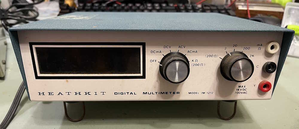
One of the things I picked up at the Fort Wayne hamfest was a Heathkit IM-1212 NIXIE DVM. This device was sold as a kit, and was also known as the Bell & Howell IMD 202-2, as well as a DeVry branded unit. They were all the same, with different branding on the front panel.
The device itself is a 2 1/2 digit meter, and uses discrete components - all ICs are common TTL stuff - to do it’s work. It’s not the most accurate thing in the world, but I imagine it was designed to help you learn about A/D conversion and other concepts while giving you a device that you could (mostly) use at the end.
This unit was sold as working, which I verified with a 120VAC inverter/battery pack from the tool company in the harbor. I offered the guy a $20 for it, which he accepted and I took my purchase home.
It’s not in bad shape for the age, a bit of discoloration on the front panel and the obligatory tape residue on the top of the device.
It came with the original instruction manual, which is useful for troubleshooting any issues.
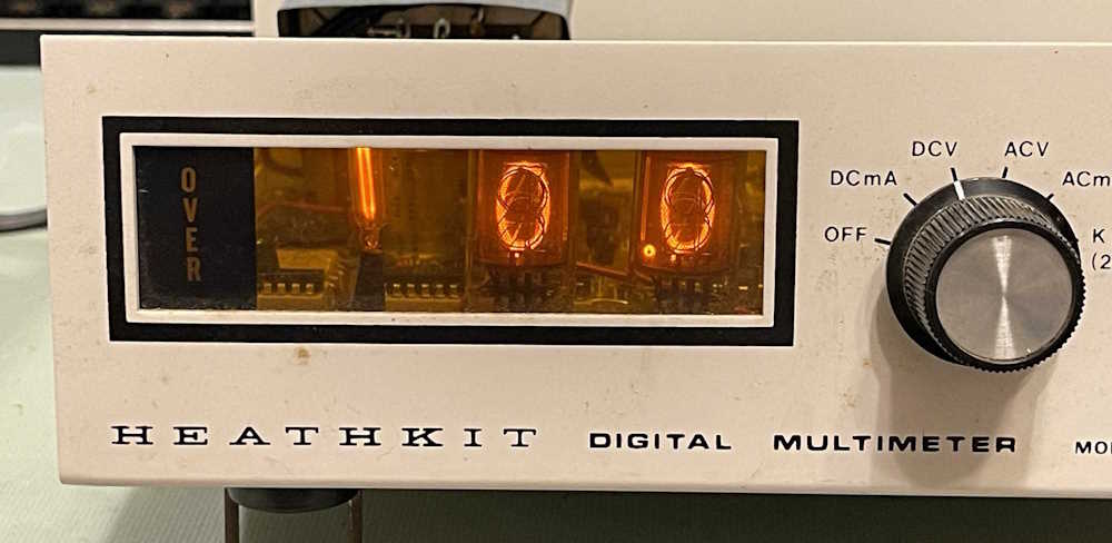
All of the tubes are nice and bright like it doesn’t have many hours on it. Even the NE-211 bulbs that are normally shot don’t exhibit any flickering or problems ionizing.
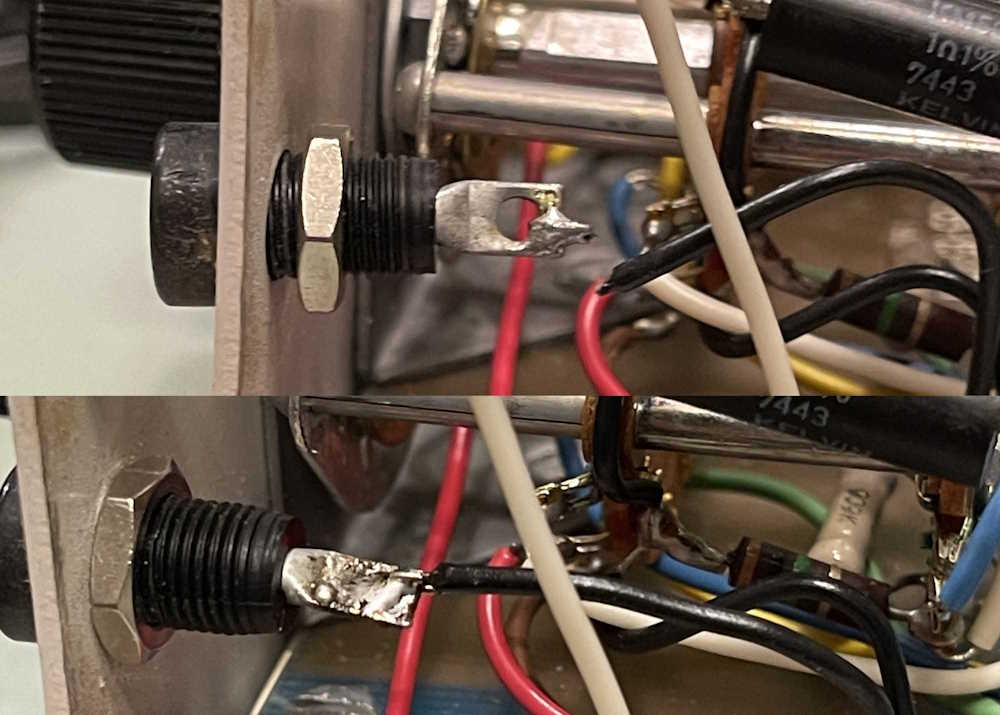
I did notice a few issues, there’s a rattle inside. Something is broken. The negative jack is also loose, which is probably just a nut come loose. The device also doesn’t respond to any input - something to do with the loose negative jack, perhaps?
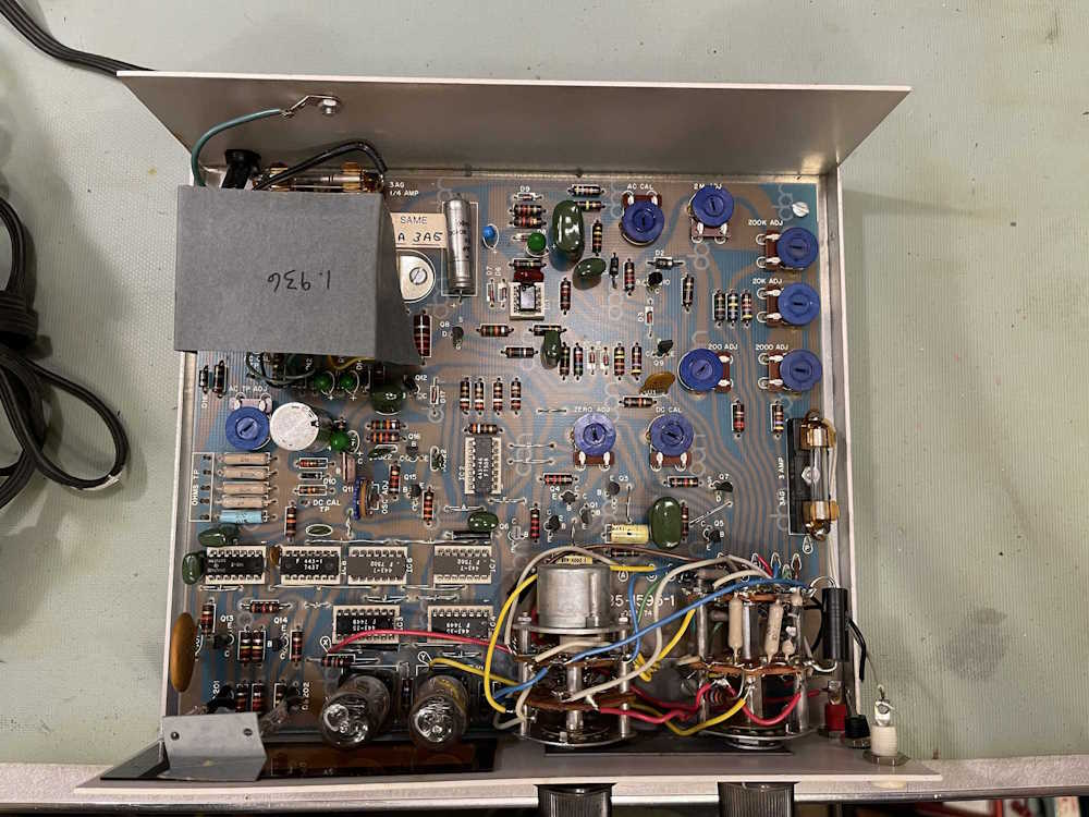
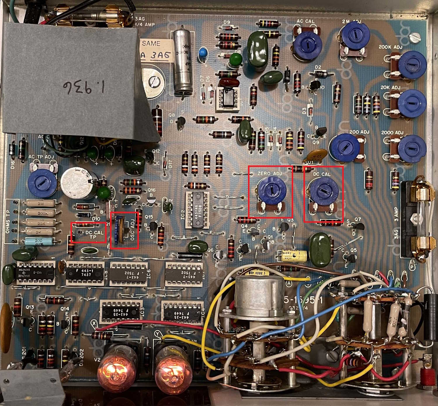
Time to open the top cover. Notice the line of big beige resistors on the left and the one blue specimen at the bottom? These are calibration resistors, and one had apparently broken at some point, as the rattle was the remains of an old part. The original owner hadn’t removed the debris for some reason.
You’ll also notice there’s a number written on the paper cover. This is the DC calibration voltage as provided by Heath. It’s wrong, so ignore it and get a good 3 2/3 digit meter and measure the DC cal point. Mine turned out to be 1.901, so I used that later during calibration.
I discarded the broken pieces and looked at the negative jack. Sure enough, the nut was backed off, and that was because the cheap plastic threads on the jack were worn. While it tightened up, one more turn would knock it back. That will have to be replaced if I want to put this into service, but I think where it’s going it will be connected and let set as a monitor device.
The loose jack was also the cause of the no reading issue. The loose jack and solid wire insured the wire itself broke. That was an easy fix, just a quick re-solder and we’re back in business.
Time to hook it up to a power supply and see what it reads. It’s close, I guess for something of unknown quality it’s fine. As I stated earlier, these weren’t known for being the most accurate of devices, nor were they known for staying where you put them. Fortunately, the DC calibration is pretty easy, just requiring the device having been on for some time to temperature stabilize.
I don’t think there’s much more to say about this device that hasn’t been said already by many others. I’m planning on making a small board that switches between the different voltages in my network rack, so that may show up at some point. Until then, stay tuned for pictures from Fort Wayne and the Scott Antique Market at the Ohio Expo.
The Heathkit IM-1212 DVM is a 2 1/2 digit multimeter sold by Heathkit (obviously!) as well as under the Bell&Howell name as the IMD 202-2. They are the same unit with a different name on the front. I’ve also been told that DeVry had one marked with their name as well, but I’ve not seen one of those.
(Hi hobbyshoppin…will copy the actual relevant portions of the manual for you next week!)
These are not the most accurate meters, and are hard to keep in cal. DC calibration is fortunately, fairly easy.
We’re interested in 4 spots in this meter, indicated by the red outlines in the image. They are, from left to right:
1: The DC CAL test point.
2: The OSC adjustment.
3: The ZERO adjustment.
4: The DC CAL adjustment.
(click on the image to enlarge)
What you’ll need:
A small flatblade screwdriver to turn pots. A plastic alignment tool will work best if you have it.
A meter with at least 3 1/2 digits of accuracy
A cliplead
Start by removing the screws for the cover. Look inside and make sure nothing looks burnt or damaged. If you’re good, put the cover back on, and apply power to the unit. Turn it on, and set it to DC Volts, “2” range.
Let it set with power on. The manual suggests 15-30 minutes warmup time, but I say give it a few days. You want this thing to be as warm as it’s going to get. Just let it set. It needs to be nice and temperature stable.
When it’s warmed up, remove the top cover. Start by looking at the paper on the transformer. There’s probably a number written there. Ignore it. That’s the DC CAL voltage as suggested by Heath. It’s wrong.
With your negative lead on the black jack on the front (all measurements are in reference to this jack) measure the DC voltage on the DC CAL test point. It should be 1.9xx-ish. It may be 2.xxx or 1.8xx, but note that to 3 digits. For example, mine states 1.936V, but the actual measurement was 1.901V. Note your voltage somewhere for later use.
Note: This voltage is generated by two crappy carbon comp resistors, so it’s going to drift as well. If you have something with a known voltage around 1.9V, then use it instead!
Jumper the red and black jacks. Using the ZERO adjustment, turn it until you get to 0.01, and then turn it until it JUST goes to 0.00. Heath suggests that at this point, the reading should flicker between 0.00 and 0.01. I usually just set it to 0.00 and don’t worry about it.
This part isn’t in the manual. I don’t know if it will help, but it may get you closer to the specified oscillator value…
Change to KOHMS and open the top. Let it set for a while open circuit so you’re getting the oscillator number. When it’s stopped changing, note it. Put the cover back on and observe the drift. When it’s stopped drifting, note this value as well. When you have the top off to adjust the oscillator, adjust it so that you’re accounting for the drift - i.e. if it drifts up, set it X counts lower, etc.
Or, just do what the manual says and…
Remove the jumper and change the input to KOHMS. The OVER lamp should be lit at this point, you want an open circuit. Using the OSC adjustment, adjust so the display reads .85.
Change back to DC Volts. Connect the red jack to the DC CAL test point. Adjust the DC CAL adjustment so the meter reads as close to your measured voltage as possible. Round the number based on the last digit of your measured voltage. Round up for 6, down for 5.
At this point, you should be able to get a good DC measurement out of the device. Be aware that it’s not very accurate, and on the 20 range you’re going to have a +/- of 0.5V. You may want to go through and adjust things again later after the unit has warmed up more, but you’re never going to get a super accurate reading out of this device.
That’s it for DC. If you want to do the rest of the calibration, I’ve copied the relevant portions of the manual and placed them here:
Fort Wayne was pretty good this year, and I have a lot of pictures to process and upload.
In the meantime here’s a bit on a device I picked up. It’s a 2 1/3 digit DVM made by … I don’t know. I’ve seen it sold as Heathkit, Bell&Howell, and others. It’s not the most accurate thing in the world, but it was easy to put together and looks to be a good tool for teaching basic A/D concepts. It’s very drift-y, and from what I can tell was known to be such even when it was new. It’s still cool, however.
It required some minor work and adjustments to get it up and running, which I’ve documented and will post later - but in the meantime, here’s the device doing integrations on a low speed sine wave. It counts as fast as the TTL silicon will allow it.
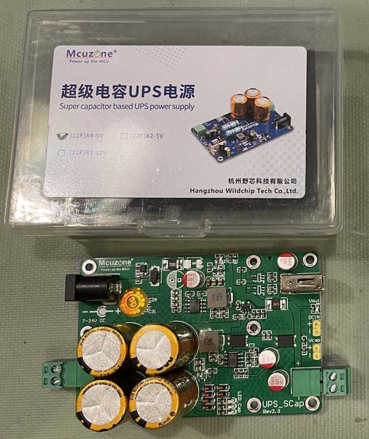
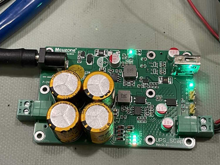
Some time ago, I picked up two supercapacitor UPS devices from Aliexpress.
They’re 22F, 12V in, 5V out, and run about $23 per with free shipping. They’re available here: https://www.aliexpre … 256804670683100.html if you’re so inclined. This isn’t a suggestion or reccomendation, just one of the places you can get this item.
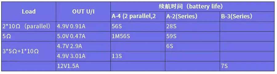
Within the sales page is an output time chart:
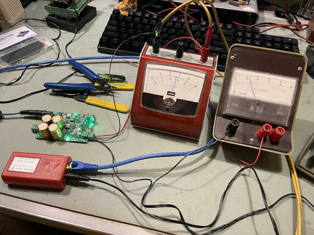
But who knows if this is correct, it wouldn’t be the first time that a vendor has overrated the capabilities of a new technology. I decided to set up a test of my own to see what happens. For this test, I selected the following items:
A 2A 12V switching wall wart from an old hard drive.
The Supercapacitor UPS, “Bundle 2” from Aliexpress.
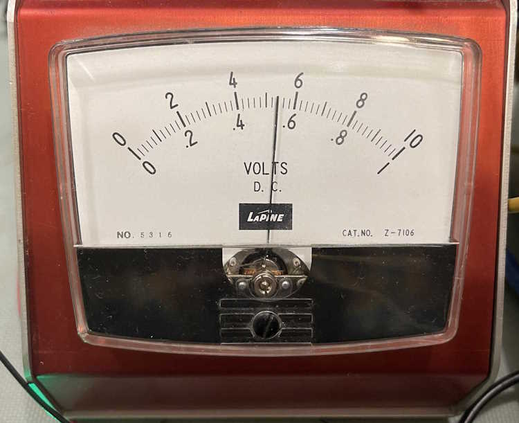
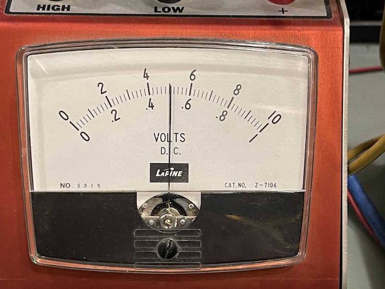
A 0-10V laboratory meter.
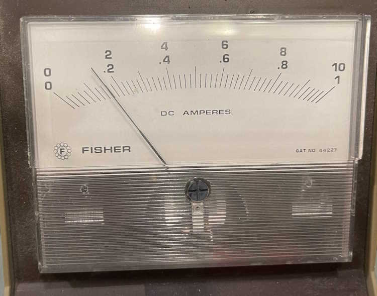
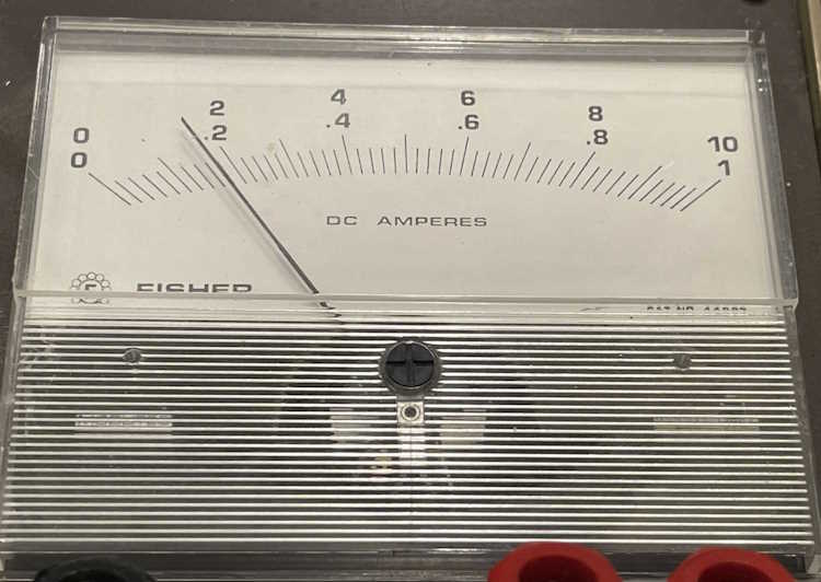
A 0-1A laboratory meter.
A Rat Shack “Micronta” digital voltmeter.
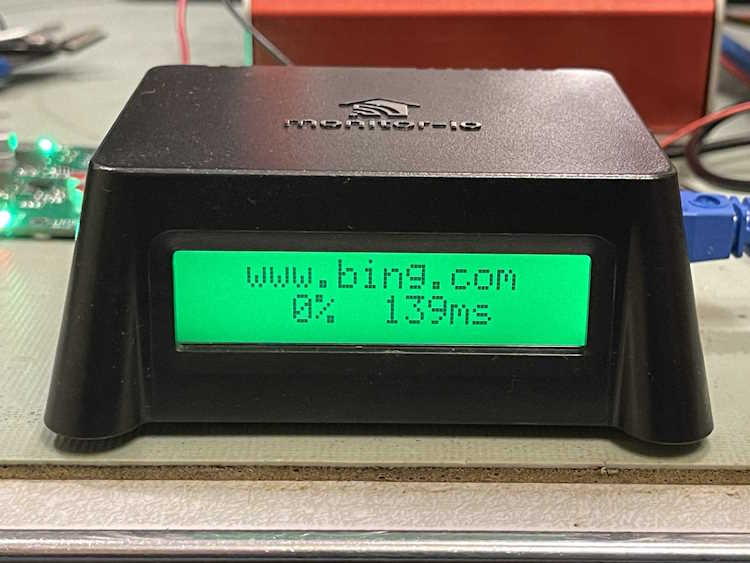
An Orange Pi 1 with display in a “Monitor-IO” case.
Cables and connectors.
Specifications of the UPS itself:
Input: 12V via screw terminals or barrel jack.
Output: 5V at 3A max via USB-A or screw terminals
Charge and power indicator lamps
There is a version that is 12V output on both the screw terminals and USB-A jack, so if you make a purchase insure you are getting the right model!
Hookup is relatively straightforward, so I’m not going to draw a schematic, but: 12V goes in to the UPS, and comes out the 5V side. A voltmeter is across the load, and an ammeter is in series with the load. The load, of course, being the Orange Pi 1.
The Orange Pi 1 is an Allwinner H3 Quad-Core A7 CPU and has 512MB onboard. It’s booting from a uSD card and powers a simple 2-line display with RGB backlighting. It’s currently running the standard Armbian build with a ping monitor program.
Originally, this device was sold by a company called Monitor-IO as a network monitoring and intrusion device. When the company shut their doors (and the backend of the device,) they provided a simplified version of the applications for those of us who had the devices. Other than their special sauce, it’s simply a standard OP1 with Linux.
Booting the device reveals that it will spike to about 400mA of current draw, but settles down to an average of around 180mA with minor spikes as the network is accessed. These are very small in time and current consumption, so they don’t really affect much.
Voltage output while charging is 5.35 volts, and current draw on the testbed is about 180mA.
First test was to see how long the device takes to charge. With 12V 2A input and 180mA output, I observed the following approximate times. These are times indicated by when the charge indicator LEDs lit fully, and are approximate because some of it is subjective:
1st LED (Red): 180s
2nd LED (Grn): 240s
3rd LED (Grn): 330s
The LEDs have a very fast flicker while charging, and you can kind of see this when you squint at it. When the flicker vanished, I assumed that the device had reached full charge, which happened at about 5m 30s. I’m going to assume that no matter what kind of current you give it, this is going to be limited as not to short-circuit the input power supply when the capacitors are charging.
Second test was to see how long the device will hold itself up before charge is exhausted. As with the charging test, each of the times is when the appropriate LED went out. I did observe a voltage output change during this time, which is noted below. Each of the noted times is from input power removal, and again, is approximate.
Power drops to 5.00V: 5s
1st LED (Grn): 240s
2nd LED (Grn): 280s
3rd LED (Red): 346s > power off.
The output at power off drops to 0.603V, and stays there for some time.
At 180mA, you get well over 5 minutes of up-time to safely shut down your machine. If we extrapolate this up to 1A, you should get about 55s of up-time, which corresponds to the life chart and is still plenty of time to shut your machine down safely, assuming you do it within a few seconds of power failure. The device offers a soft-switch to signal power off events to the device in question, if you’re so inclined - but I did not test this as it’s not going to meet my needs. I’m planning on spinning up a simple board with some reed relays on it to provide my monitoring equipment a dry contact for notifications.
In all, this is fine device for smaller SBCs and any device that’s running on 5V, and you don’t have to worry about replacing batteries. It’s not going to be useful for some of the newer devices that require up to 5A of 5V, but for the device in question (and probably things up to the Pi2/3) it’s a good, cheap solution - something that’s quite rare in this day and age.
The only things that may trip you up are the slightly high 5V when there’s input power, and the 0.603V after power off. Most SBCs probably won’t mind either of these, but if you have a sensitive device it could cause problems.
I give these devices a thumbs up, and plan on implementing a few of them around the network.


 buggy works.")


 went home with me.")


 now silent key.")