An Eico 145 Signal Tracer - Part 3
Sunday, April 21, 2024 at 12:57:15
Now that I’ve verified that the unit works, it’s time to get it ready for rebuild - that means ordering parts.
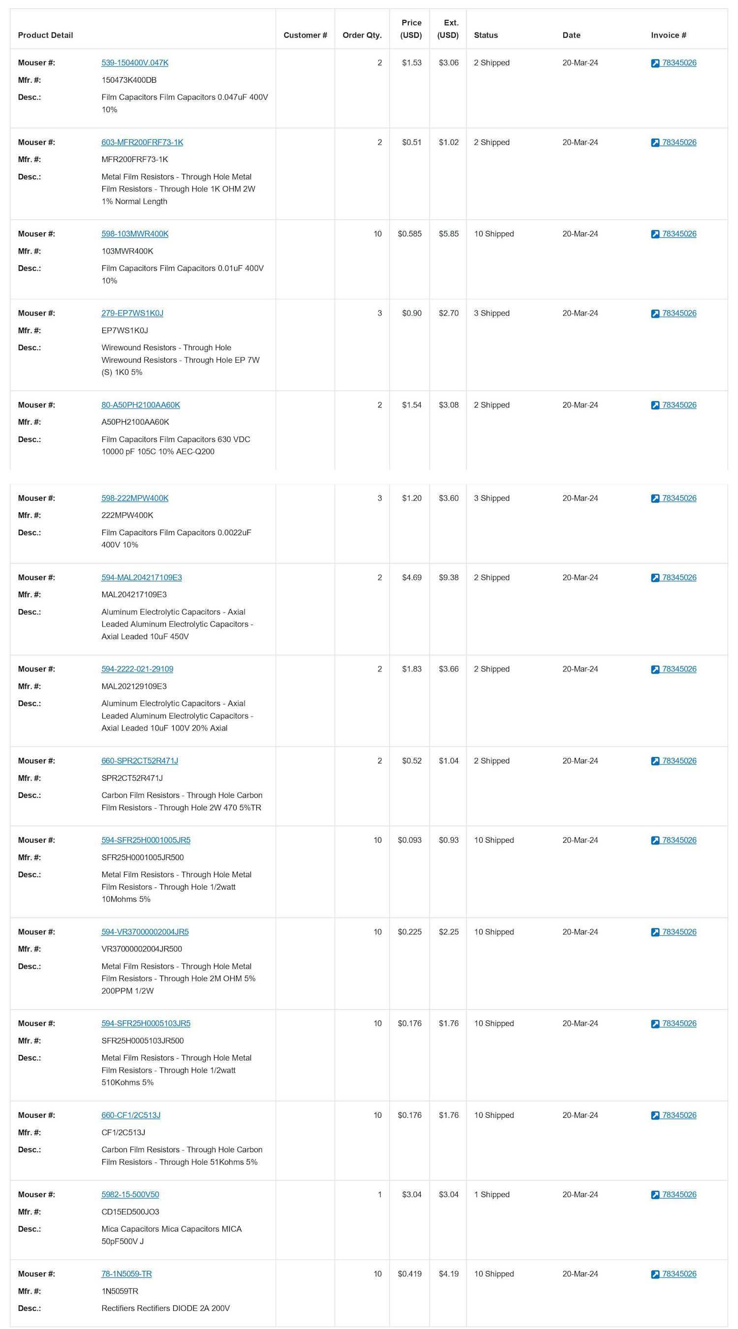
I’ve created a list of parts to order. I’ve stayed with carbon film resistors, or metal film if they were more reasonable - carbon film seems to be fading in availability. I did make two changes - one is the cathode resistor for the 6K6 output tube, the other is the power supply divider.
From everything I’ve read, the 6K6 was run a little hotter than than it should have been, and a 1K (versus the original 470 ohm) has been used to cut down on the output power. We’re not really concerned with power output here, this is a signal tracer - not a stereo amp. This should help any new output tube used stay useful longer.
It’s still a 2W resistor, metal film instead of the original carbon comp. The bypass capacitor has also been re-added, as it appears to have never been installed.
The second change is the power supply divider resistor. This has been increased to a 7W resistor with a voltage rating high enough to withstand the power supply voltage. You’ll notice in the original pictures, this was a long carbon comp resistor. While power is a concern here, the the voltage rating of the resistor is the main concern. 300V in a power supply could arc across a short carbon comp resistor, To increase the voltage rating, they were simply made longer to give you more space between input and output.
Now, that’s not a problem (as much,) but you still need to be mindful of the voltage rating of the part. In this case, I’ve chosen 500V. This, and the power rating far exceed what’s needed. However - it’s wirewound instead of comp. Inductance in the circuit could change the output voltage a little. Not that we really care, but it’s something to watch out for. I certainly wouldn’t do this in the audio part of the circuit.
All capacitors are as close to the values as you can get in a modern part. 0.01s are readily available. 0.05 is now 0.047, 0.002 is now 0.0022. All are 400V, except for the across-the-line capacitor, which I chose 630V for. The 50pF mica is probably fine, but a new one was purchased just in case.
Electrolytics, of course, have to go. 8uF are now 10uF. This is both someplace you don’t want to scrimp on, but you don’t want to go crazy with. You don’t need transistor device filtering here, so always stay around the original value. With 8uF, you could use 10, 15, 22…no issues. Don’t start sticking 100, 1000, or more in there - you don’t need it, you run the risk of drawing too much current off the tube as the capacitor charges, and you’ll spend a fortune getting parts with that high of a capacitance and a voltage rating.
There are two schools of thought here on voltage rating for capacitors. One states that higher is better, the other states going far higher than your expected voltage will eventually destroy the part as they can’t stay formed properly. I can’t speak for either, but I was always taught give yourself some headroom but don’t go wild - so that’s what I did here for the electrolytics. I expect 300V max, I went with 450WVDC.
In all, I spent about $48 on parts. Most of that is the electrolytics and the higher power resistors. I could have cut that back some, but I always like to order a few extra parts. It’s not like they won’t get used later.
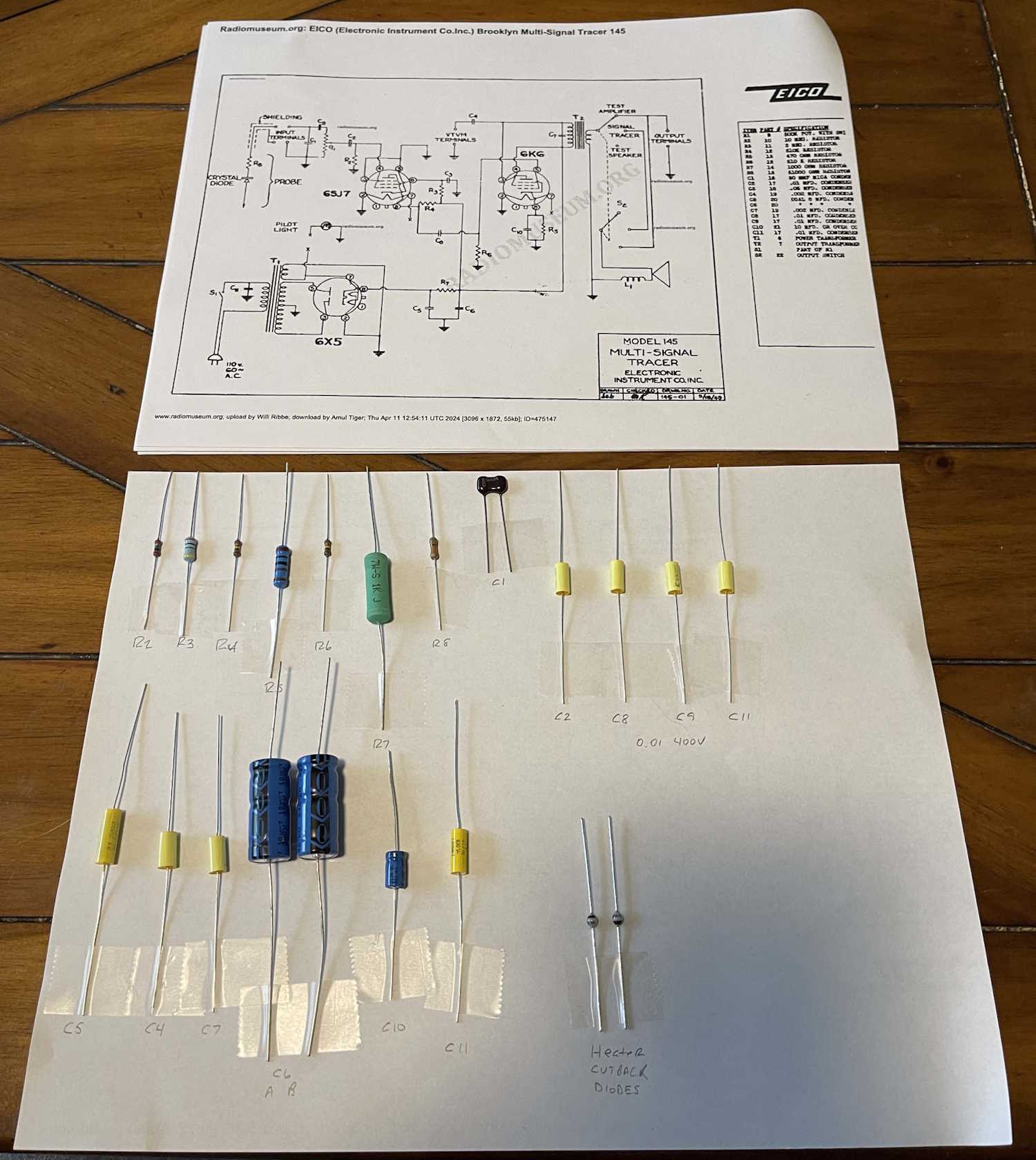
There’s one other modification I’m going to make here, and that’s the addition of a couple of diodes in the heater line for the tubes. These units were designed to run on 110VAC, not the common 125VAC we get today. That means you get about 7.1VAC on the heaters - far in excess of their rated 6.3VAC. Two diodes, back to back, should cut about 0.6V off, bringing you to a much better 6.5VAC. Still high, but it’s not going to destroy the heaters as quickly. If you really want to be ideal with the thing, a variac to bring input voltage down is the best option - but if you’re going to have this in places that aren’t your bench, the diodes are a good option. I chose 200V, 2A 1N5059 units here - mostly because they were inexpensive and about 2x rated current, and somewhat because these round glass body diodes look kind of cool. They’ll go on a phenolic terminal strip.
Next step was to inventory everything and compare it to the schematic and parts list. There’s not a lot here, but I seem to have everything I need save for the bits I’m going to get from stock at the bench.
Next step is rebuilding…do I want to just yank everything and replace it all at once or do it part by part? It’s probably best to do it the latter way, but doing it the former way allows you to clean up everything and make it look nice. I’ll think about that for a while.
Until then, stay tuned!
Edit: I did decide to go with a nice aluminum cased resistor for the power supply divider. The one I originally chose was wirewound, that shouldn’t make a difference - but a nice resistor with a heat sink should keep this thing going for years.
Next part of this series: https://wereboar.com … ignal-tracer-part-4/
Previous part of this series: https://wereboar.com … ignal-tracer-part-2/
Wrapup and link to all posts: https://wereboar.com … -and-final-thoughts/