An Eico 145 Signal Tracer - Part 6a - Starting the rebuild
Saturday, September 21, 2024 at 19:50:47
This post starts the rebuilding of the Eico 145 signal tracer I’ve been working with since picking it up at the Breezeshooter’s Hamfest in 2023. This will consist of probably 4-6 parts (maybe more,) depending on how much time I have to work on it.
The first part is starting the power supply - I’m not going to do this exactly as the manual says, since there will be some extra stuff on the chassis. I’m going to do the power supply completely, then generally follow the assembly manual for the rest of the device.
First things first, I noticed the 4 position terminal strip closest to the rectifier tube couldn’t be mounted like the assembly drawing shows - it’s too long! That’s why the original builder chose to turn it to the side. No matter, I needed more positions so I put a longer strip in and turned it perpendicular to what the manual said. This gave me some room to add the two heater cutback diodes at the top of the strip. I didn’t bend those leads in, but chose just to drop them in the strip and solder. No, that’s not the way you’re supposed to do it, but I made sure the solder joint was solid.
I’m trying to keep the AC all in one spot, except for the filaments which obviously have to run across the chassis.
One thing you should note here is that one side of the filaments, and the center tap of the primary all go directly to chassis. This may seem kind of odd, but it helps reduce the hum present in the unit. Instead of connecting grounds everywhere, I tried to keep all of the AC running to the same ground tab. We’ll see if that makes any difference.
It is kind of a mess here, but I didn’t want to cut wire off the transformers, so I looped it where needed, and used the length to try and neatly run things to their destination. It is what it is.
Everything except for the filaments, and the AC return from the switch has been wired in. I’ll do the rest once I get the proper color of wire (more on that later.)
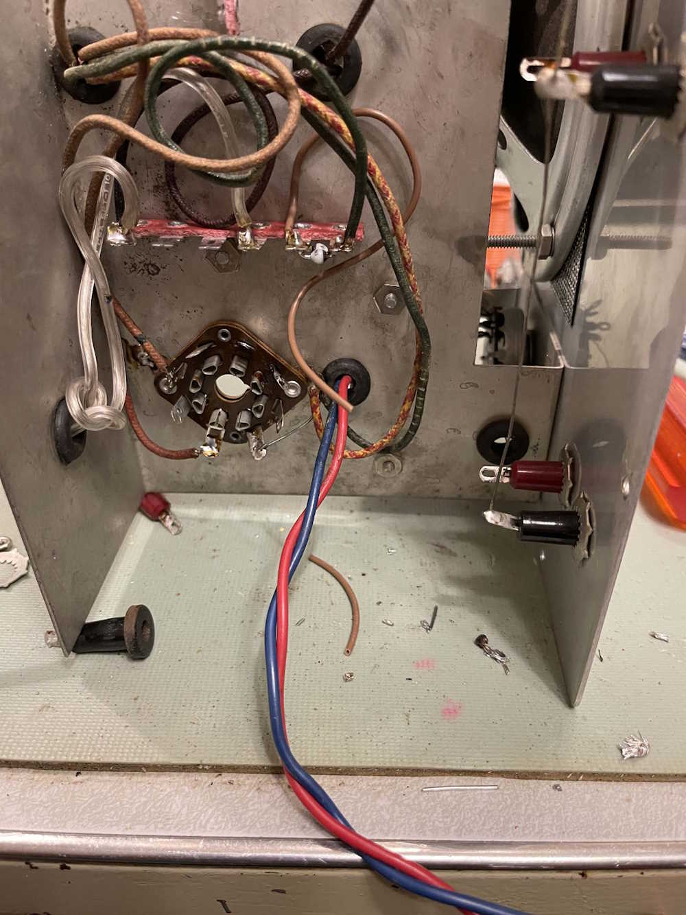
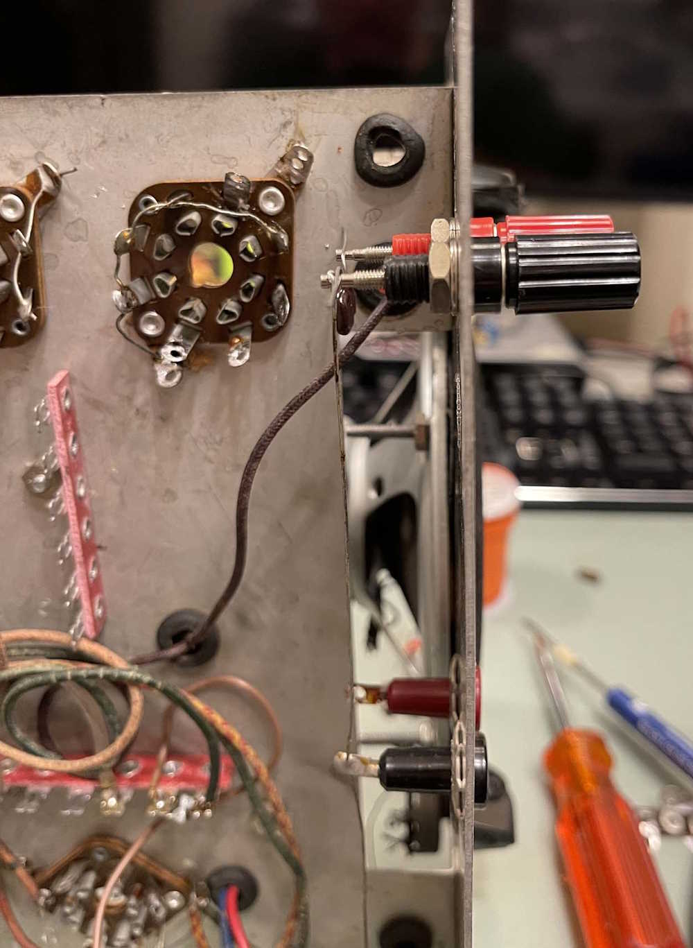
The only other part I did tonight was replace the front panel pin jacks on the input with a nice set of banana jacks. These are much more useful to me than the pin jacks. Note the new 50pF mica laying on the terminals, this was being sized but I don’t want to solder it in until I get some more wire.
Next part will involve placing the new filters and the rest of the power supply components.
Next part of this series: https://wereboar.com … ng-the-power-supply/
Previous part of this series: https://wereboar.com … cer-component-notes/
Wrapup and link to all posts: https://wereboar.com … -and-final-thoughts/