- 2024
- Dec
- 3
An Olson TE-189 C-R Analyzer - Considerations
I’m getting ready to replace some of the parts in this device, and I decided to take a look at what I’m doing and consider things.
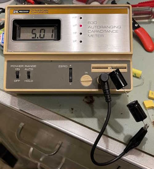
I recently cleaned up an older B&K Capacitor Checker, and (in theory) this device should be a good reference instrument for measuring parts in this device. I decided to check things and it made me wonder if I really should replace all of them. There are some that will most certainly get a new part in their place, but others…
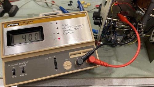
The first is the 400pF mica capacitor. I originally thought this thing was a mod, as it has a capacitor and a trimmer. However, I’ve seen another unit under rebuild and it has the same thing. The trimmer itself is plastic, so there’s no way this thing is approaching 600V, but it adjusted down perfectly and I had a good 400pF on the meter.
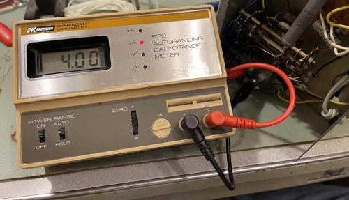
The big 4μF was similarly in good condition with this meter.
This one has good ESR and has a big 1k resistor to absorb the brunt of any voltage, so I think this and the 400pF will just be left alone for now. I have replacements in case they do need to go, but they don’t right now.
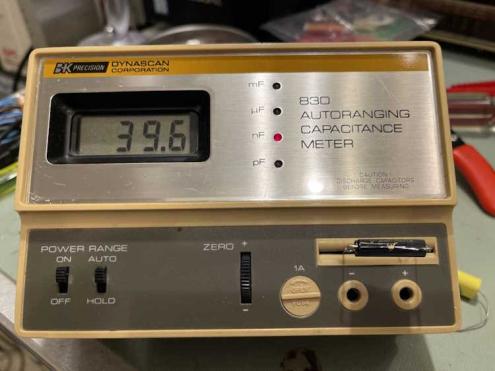
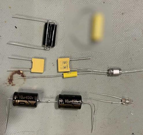
What does need to go is all of these metal can parts, especially the across the line capacitors and the filter. For the 40nF capacitor, I chose some 1% film parts at 630V and paralleled two of them for 40nF:
For the filter, two 10μF in series at 450V to make a 5μF at 900V. This part will probably get some heat shrink to strengthen the assembly. I chose this route because it was much cheaper than trying to find a part rated the appropriate voltage.
There are some resistors as well that seem out of tolerance, but those will need to wait. It’s not like this thing is going to be as accurate as a modern digital meter, but my concern was to prevent electrical problems.
The entire parts set to be replaced (save the 4μF):
1x 5μF filter capacitor assembly, electrolytic.
1x 40nF test capacitor assembly, film.
1x 0.01μF input blocking capacitor, film.
1x 1500pF capacitor for the eye, polystyrene.
2x 0.047μF across the line capacitors, safety film.
1x A1C neon bulb for the front panel.
Also, I am going to replace a poorly placed 1MΩ resistor across the eye tube, and perhaps the 1K and 500Ω resistors used in the test circuit (with the 500Ω just kind of hanging there in the air.) The latter two are both high-wattage parts (of unknown power) so a 10W part should be more than plenty on these.
That’s it for now - the next step is to put the parts in. That shouldn’t take long, but I’m also going to clean up some of the wiring as it’s in terrible shape. Stay tuned!
Next part of this series: https://wereboar.com … yzer-rebuild-part-1/
Previous part of this series: https://wereboar.com … some-notes-on-parts/
