- 2024
- Dec
- 4
An Olson TE-189 C-R Analyzer - Rebuild, part 1.
SO…I thought that the TE-189 job would just be some tidy up and new capacitors. No, that’s not going to work. Turns out that the builder of this device (I hope this was a kit!) managed to get about 50% of the solder joints to hold. The rest were nothing more than burnt wire and insulation, badly wetted connections, and connections that were just kind of wrapped around one another and soldered with prayer.
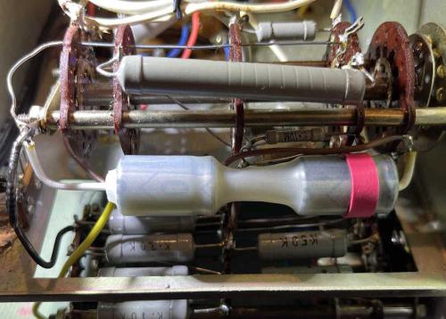
I spent some time last night installing the new filter capacitor. Since a 5μF @ 700VDC is kind of hard to get at a reasonable price, I chose to use two 10μF @ 450VDC instead. These were connected in series to give the requisite capacity at 900VDC. I wrapped them in heatshrink and gave it a red band to identify the positive side of the device. That’s when I started to notice how badly the thing was wired.
You can see a brown wire attached to the same terminal as the positive side of the filter. This wire was just kind of stuck in the solder and came right off when I hit it with the iron. There was enough left that I could cut and strip and insert properly.
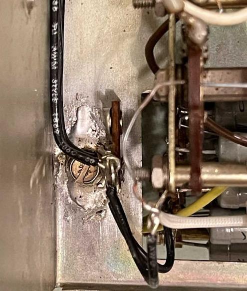
The grounds on this thing are a complete mess. A small terminal on the switch had multiple leads inserted in it - rather, attached to it. One was in it. One was wrapped on it. One just kind of hung there. A big blog of solder attempted to hold it all together. Grounds are flying everywhere in this thing instead of coming back to a single point. Plenty of other wires were the same with some just wrapped around other leads and soldered right into the insulation. Even the original filter was a wrap-job and wasn’t wetted properly.
How did this thing even work? Or did it? The neon bulb was dead so it spent some time on during it’s life…
I decided to solder a terminal strip directly to the chassis. Clean and wet the chassis and terminal, and hit it with the 80W iron. I know I’m talking about solder quality, but my 80W device is just not enough for this task. I’ll pick up something bigger this year. It did a (poor looking) job, so all grounds will now come back to this point.
There are around 10-ish ground connections going to all different places in the unit. I’m going to run them back to this double lug so they’re all at the same point. That involves removing a lot of other stuff, including jumpers across the transformer terminals, and a lot of stuff on the other side of the chassis. I’m going to run all of these and then slowly work my way across replacing wires that are in need of replacement. It’s going to be slow going.
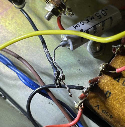
Here’s an example of what I’m seeing - this is the ground for the 450-0-450 portion of the power supply. It was just kind of shoved through a terminal on the transformer and hit with some solder that didn’t really wet the lead. The across the line cap was then wrapped around the lead and soldered without removing any insulation - the capacitor just kind of melted into the plastic and didn’t really wet. It all goes away.
There’s a big lump of grounds just to the right of this that I’ll correct, and then start replacing capacitors and fixing the tube socket and the HV power supply.
Next part of this series: https://wereboar.com … -intermission-parts/
Previous part of this series: https://wereboar.com … yzer-considerations/


