- 2024
- Dec
- 11
An Olson TE-189 C-R Analyzer - Rebuild, part 2 - I only wanted to replace some capacitors.
After digging in to this unit, I determined that it was a basket case. While the unit itself wasn’t baked, the builder most certainly was. Probably less than 1 out of 5 wires in this thing (that weren’t bare interconnects on switches) was soldered securely. The rest? Bad or no solders, wires pulling out of their terminal, no wetting, too much solder, blobs everywhere. Burnt wires, solder drips…you name it. This thing was a how to on how to not solder. I realized that if I wanted to see this thing work reliably, it was going to be a partial rewire.
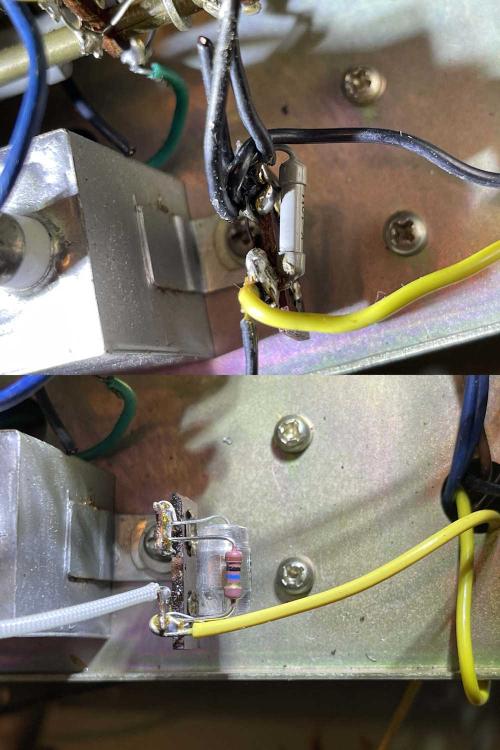
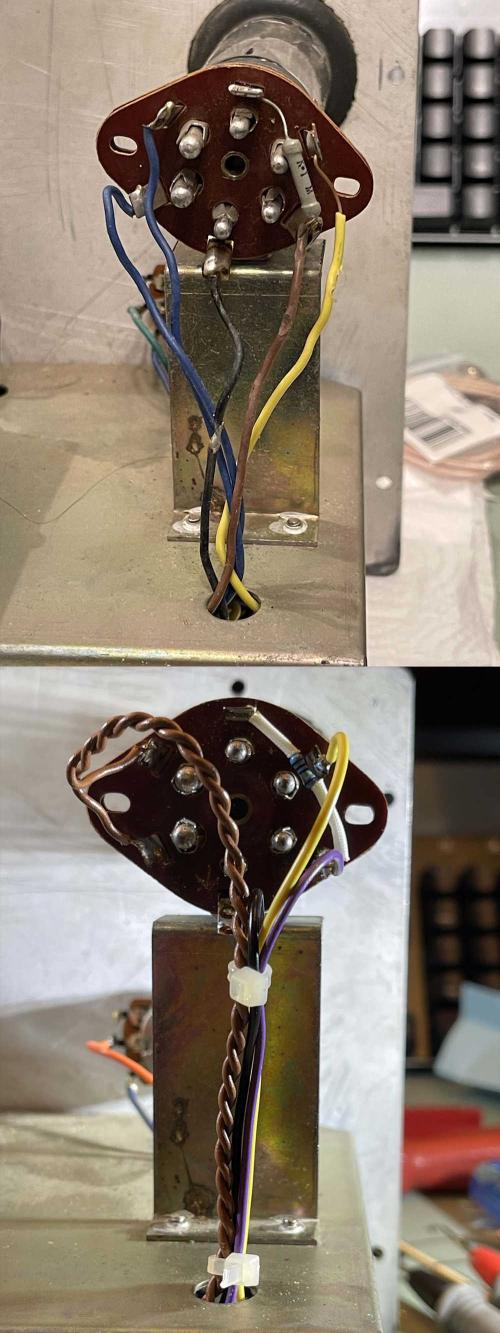
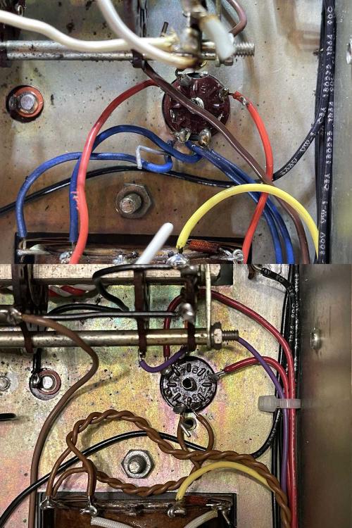
Here are some before and after shots of the cleanup crew’s work:
First is part of the drive for the eye tube. This consists of a capacitor coming in from the terminals on the front, a 1500pF capacitor, and a 10MΩ resistor on a terminal strip…with lots and lots of grounds attempting to terminate here as well.
All of the grounds were removed and single-pointed back to the other side of the chassis. The old parts were replaced with new, high quality parts - the input capacitor went from one of those leaky metal can Japanese parts to a new film cap, the 1500pF ceramic disk (with half it’s coating missing) is now a 600V polystyrene, and the resistor is just a good metal film part. The terminal is now clean with a single wire leading to it. Unfortunately, since the screw for this also holds the 4μF capacitor, I couldn’t solder it down, but it’s tight and clean.
Next is the socket for the eye tube. Almost every wire is burnt in some place, be it here or below the chassis. The black wire is j-hooked together, and the yellow wire has far more exposed copper than is safe. Even the 1MΩ resistor is poorly placed, having too much lead on one side and a “Oops, I cut it too short” lead on the other. Here it was just rewiring everything with fresh wire and properly twisting the filament leads. The resistor now lays in the socket with the proper spaghetti coating.
Last is the tube socket for the power supply. This has quite a bit of voltage on it, so it needed cleaned up. Twisted filaments, and fresh wire leading directly out of the socket fixed this one. I admit that the copper is a bit too much, but I’m happy with the results overall. The previous build had some solder balls here, and the fialments were all terminating to this point. I’ll brush this down to get the flux off before final inspection.
Prety much everything except for a couple pieces of coated wire and a couple of capacitors that are still good have been or are being replaced, including the big 500Ω balancing resistor that was flopping around the transformer. Even the AC has been moved off to it’s own isolated terminal strip for ease of disconnect in case of trouble.
I’m waiting on some Blue wire for the measurement section of the device (I’ve tried to keep the original color scheme as much as possible) so hopefully this will be done in a week or so. Stay tuned for the final part of the build, coming soon!
Next part of this series: https://wereboar.com … er-the-waiting-game/
Previous part of this series: https://wereboar.com … -intermission-parts/


