I was hoping to present a test and performance post for you by now, but the post office isn’t cooperating with me. I ordered some various colors of wire to finish the rebuild (and have some on hand for later use,) but the materials I ordered have decided to take a tour of a few states, as well as the East side of Columbus. It’s visited a couple of places that it had no reason to go. Tonight I got notification that it’s in Kansas. (It went to Kansas again, floating around Kansas City’s two states…I’m going to wait until after Christmas and if it’s not here consider it lost.)
(It made it back to Columbus, then to the city where I work…and then vanished. I ordered a short piece to continue the project, the company I bought the wire from eventually considered it lost and replaced it all. I then received the original package in March 2025 - but the post office doesn’t know how, why, or even where it is right now!)
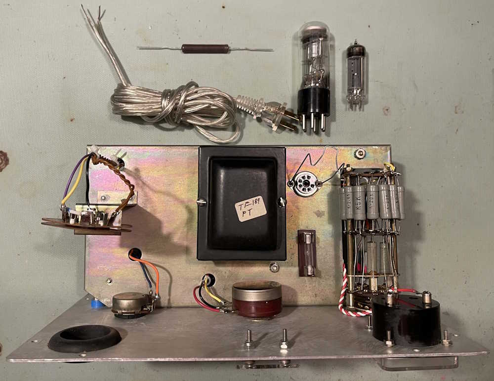
For now, I have the line cord and the 500Ω balancing resistor laid out alongside the tubes. They await the final wire I need for this build.
I have some time off over the holiday, so perhaps I’ll have received it by then. We’ll see - stay tuned!
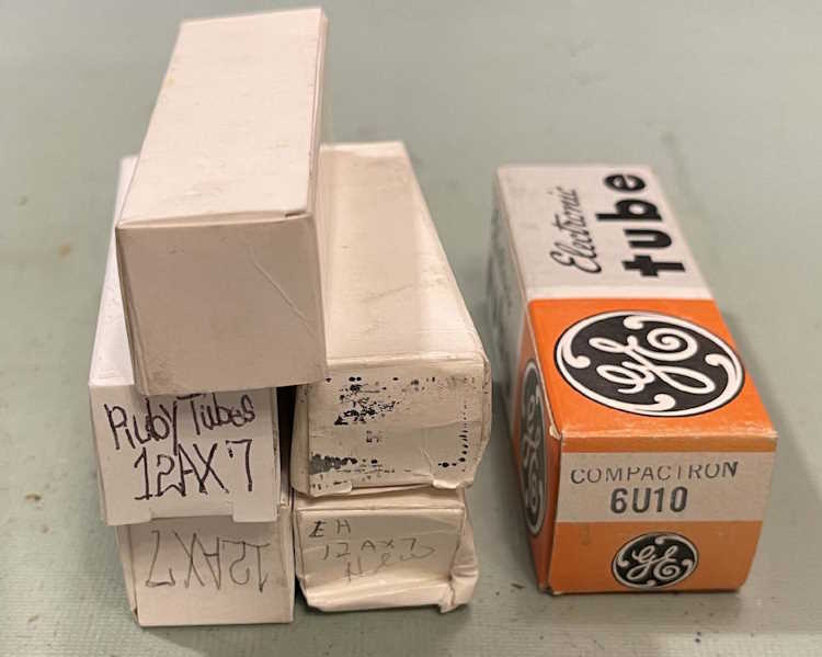
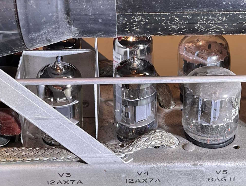
I picked this device up at the MARC hamfest in North Canton. The seller stated “Someone removed all the tubes except one” and he was right. 4 12AX7 and 1 6U10 were required to fill all of the sockets again.
This is the device in question. It looks like it requires both a horizontal and vertical input, but I’m not sure.
Thanks to Bob @ hamtubes.com, I was able to acquire the necessary tubes. I’m not sure why they were removed, they aren’t really that much unless you want old RCA branded 12AX7. The 6U10 compactron isn’t expensive at all. I chose Russian and Chinese 12AX7 because this is an instrument, not an amplifier.
A little bit about one of these tubes: the 6U10 “”compactron” was the last gasp of the tube industry. Packing up to 4 devices in a single shell, this was an attempt by GE to reduce the number of tubes required for a television set. Had these come out before the transistor era started, we might have seen more elements in a single tube, but we didn’t, and the rest is history. This particular device contains 3 triodes - probably why it was removed by the previous owner.
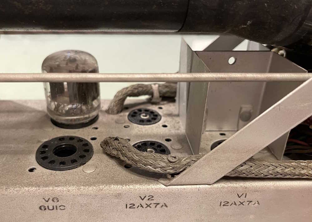
So let’s open it up and populate things. Indeed, it is empty in here:
And now it’s full:
Some of these tubes were hard to get in to their respective sockets.
I did notice the one remaining tube was Waterman branded. That’s too bad, the others probably were too. I wonder who made these - maybe I’ll pull it out sometime and see if it has an EIA code on it.
Ok, so…let’s try it. Checking across the line cord I get…nothing. Mmmmm that’s not good. No external fuses, so what’s wrong here. Start with the line cord, it goes to the fuse, then to the switch, then to the ….nothing.
Power switch is bad. It’s pretty corroded, so no surprise. Well, I’m out of time for this particular device at the moment, so a note and set it aside. Stay tuned for the next part where we turn it on for reals!
In my quest to find a small bench scope, I picked up a couple of different models for a decent price. This IO-10 was a negotiated item - I mostly didn’t want to pay the asking price because it had a missing fuse holder cap, and that usually means that someone was working in the device trying to figure out why the fuse was blowing. Other than that, the device looked to be in pretty decent physical condition.
It arrived today in a box that, when new, was just a suggestion of cardboard and it didn’t really survive the trip. Uh oh. It was crushed somewhat and I expected the worst.
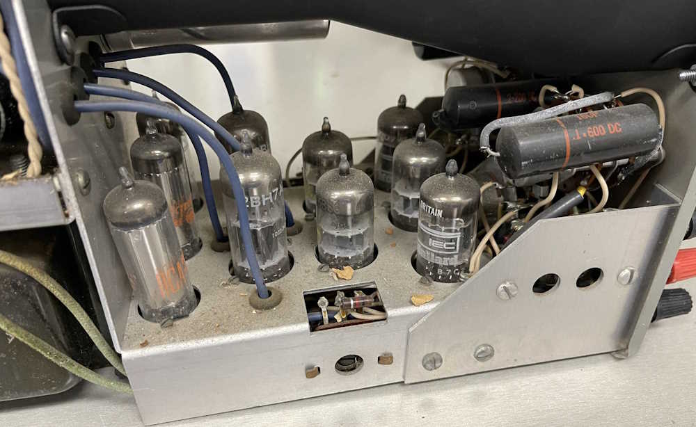
Opening revealed an apparently mostly intact device:
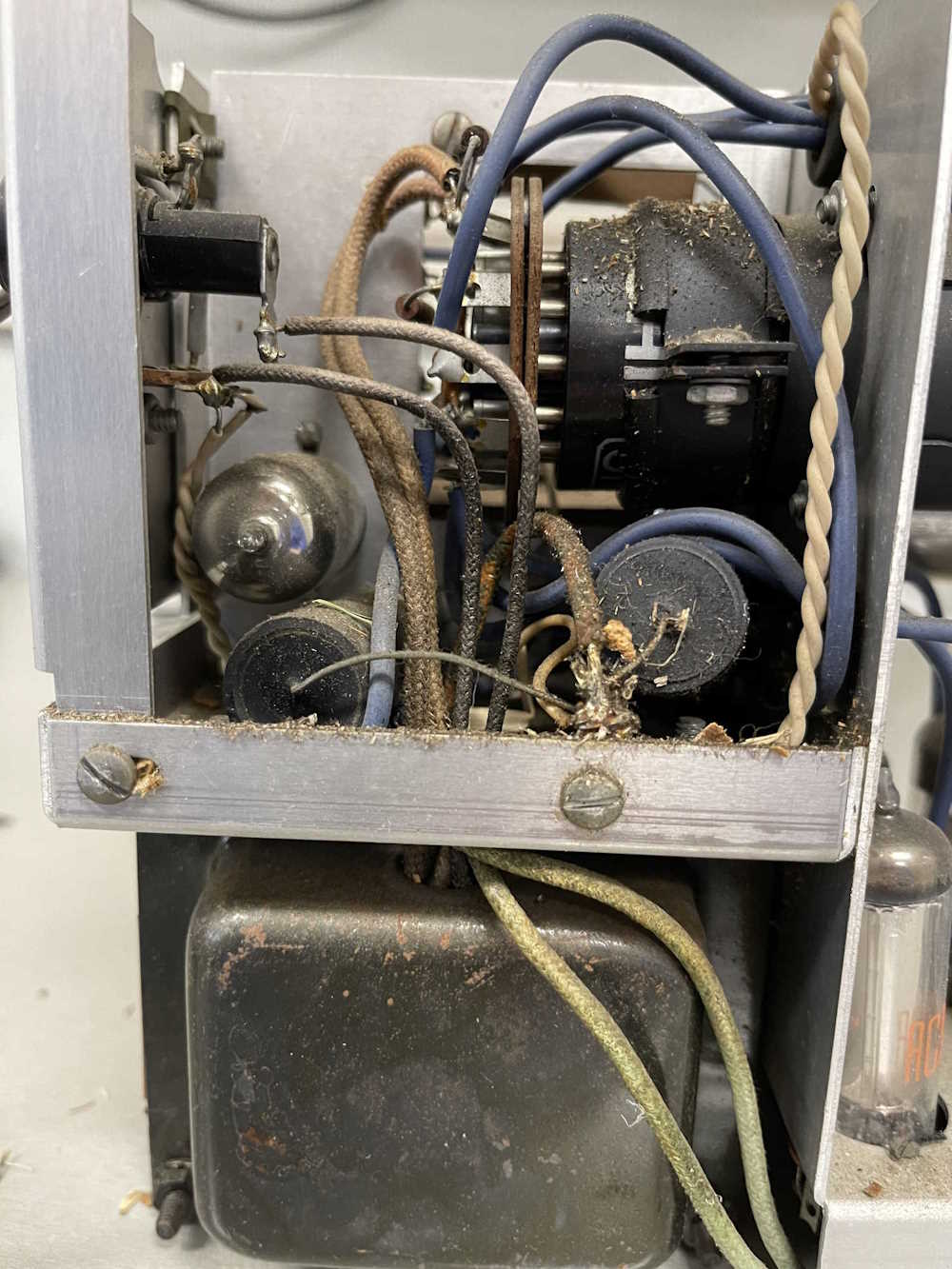
There was a lot of debris in the device. Paper, leaves, etc. I understand it had been sitting in a garage, but was it being used to shred leaves? Fortunately, all of the tubes are still in their sockets but you can tell they tried to vibrate loose. Most are the original Mullard, but there’s a couple of RCA, a Sylvania, and a GE device in here in the places you’d expect. Power supply, mostly. All covered with debris.
Most of the controls and one of the terminals are just frozen with goo and damp corrosion. This is going to need a good dousing with alcohol and tuner lube. I can’t even turn the power control. It’s locked.
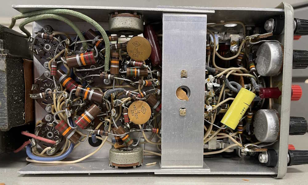
The bottom revealed a fairly late device with discs and film capacitors. The yellow one, being dated 1968, was probably replaced at some point - but this thing should be fairly easy to make work.
Unfortunately, because it wasn’t packed properly, it got damaged at some point, probably dropped on it’s corner. I am sad because this thing was otherwise in 8/10 shape. I’m going to ask a friend who does metalwork for some advice on knocking this dent out.
It doesn’t appear to have been touched except for tubes, and the one part seems to indicate this was made sometime around 1968. So, it’s not terribly old - the electrolytics may be still good (but unlikely due to garage storage.) Everything else is disc, so this shouldn’t need much more than some good filter capacitors and maybe a few of those carbon resistors replaced.
This one is going to need to wait a while before I get it on the bench, as the holidays and some work-related items are going to take priority. Check back soon for more on this device!
For the most part, the stuff I see on eBay that I like is reasonably priced. Some is excellent, some is “Let me offer you a little less”
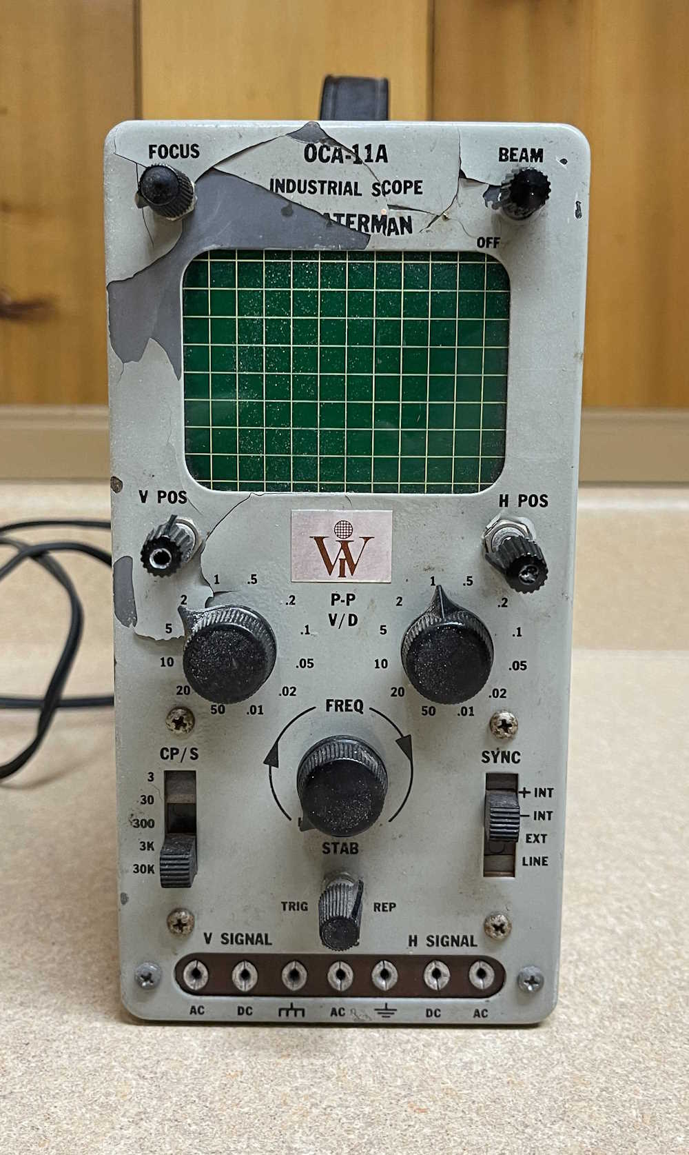
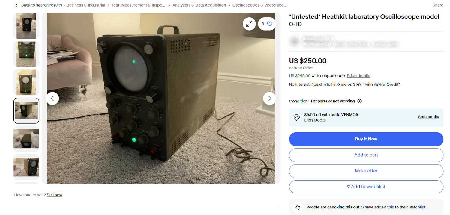
There there’s this one. Maybe the person doesn’t know what they are offering, or maybe they think because it’s “old” that it’s valuable beyond compare. Who knows, but this thing looks like B.O.B. from the Black Hole. I can’t really tell what’s happened to it beyond it’s Seen Some Stuff. Bent cabinet, bent control shafts, but surprisingly it still works. This is a $5 hamfest “Please take me” sale.
$250? Maybe if it was still in the box, and the box wasn’t opened.
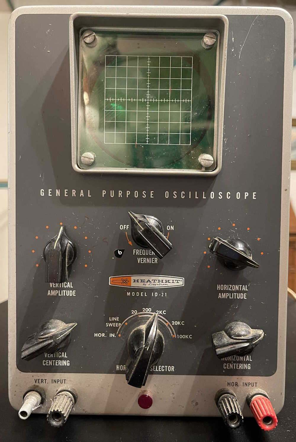
I’ve been wanting a small, AC powered oscilloscope for the bench, something that can do tube stuff without caring if you accidentally hit B+ for a second. Heathkit made several different styles that fit the bill, and I managed to run across this decent looking IO-21 3” scope for a reasonable amount.
It’s difficult to find one of these both in OK condition, and for a decent price. Like most items, people see “TOOOOB,” get some chatbot to write them garbage about how it’s a widely used accurate piece of equipment good for your toolbox, and slap a high price on it. It’s not, it’s something useful for a few of us, and the rest go and get one of those $60 Zotec Scopemeters for our toolbag.
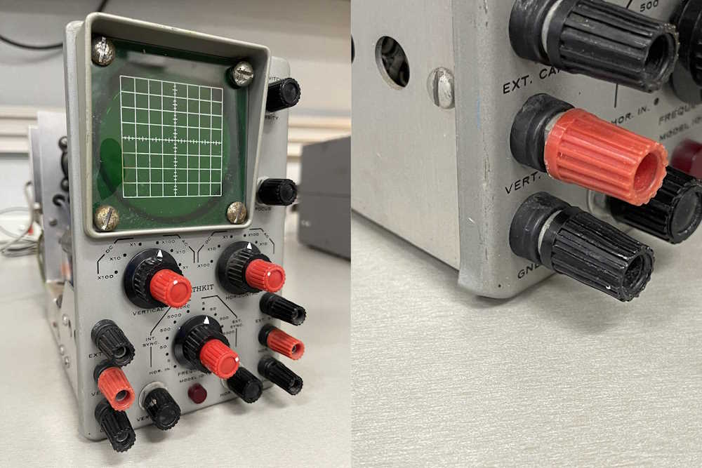
Regardless, this is in ok shape. Most of the parts are there save for a terminal cap, which is no problem. I have many of those of the correct type from dead Heathkit devices of electronics past. It’s dirty, but that’s to be expected.
Note that many will label these as 10-21, but all scopes from Heathkit of this era were “IO” series.
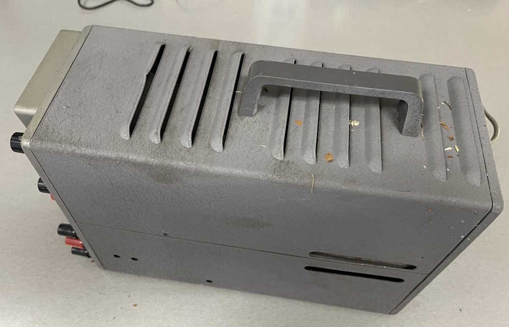
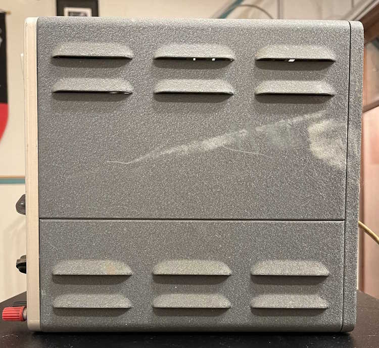
The side
is a bit scruffy, and the back exhibits some broken plastic on the direct vertical inputs.
Those are just jacks, so they can be replaced if need be.
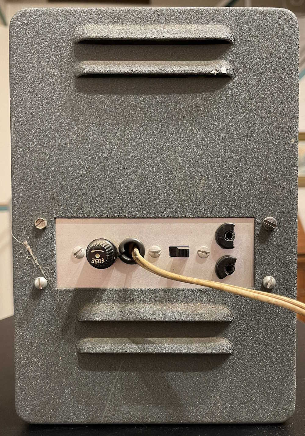
Time to take the back off…first impressions were this was built from a kit, and decently built.
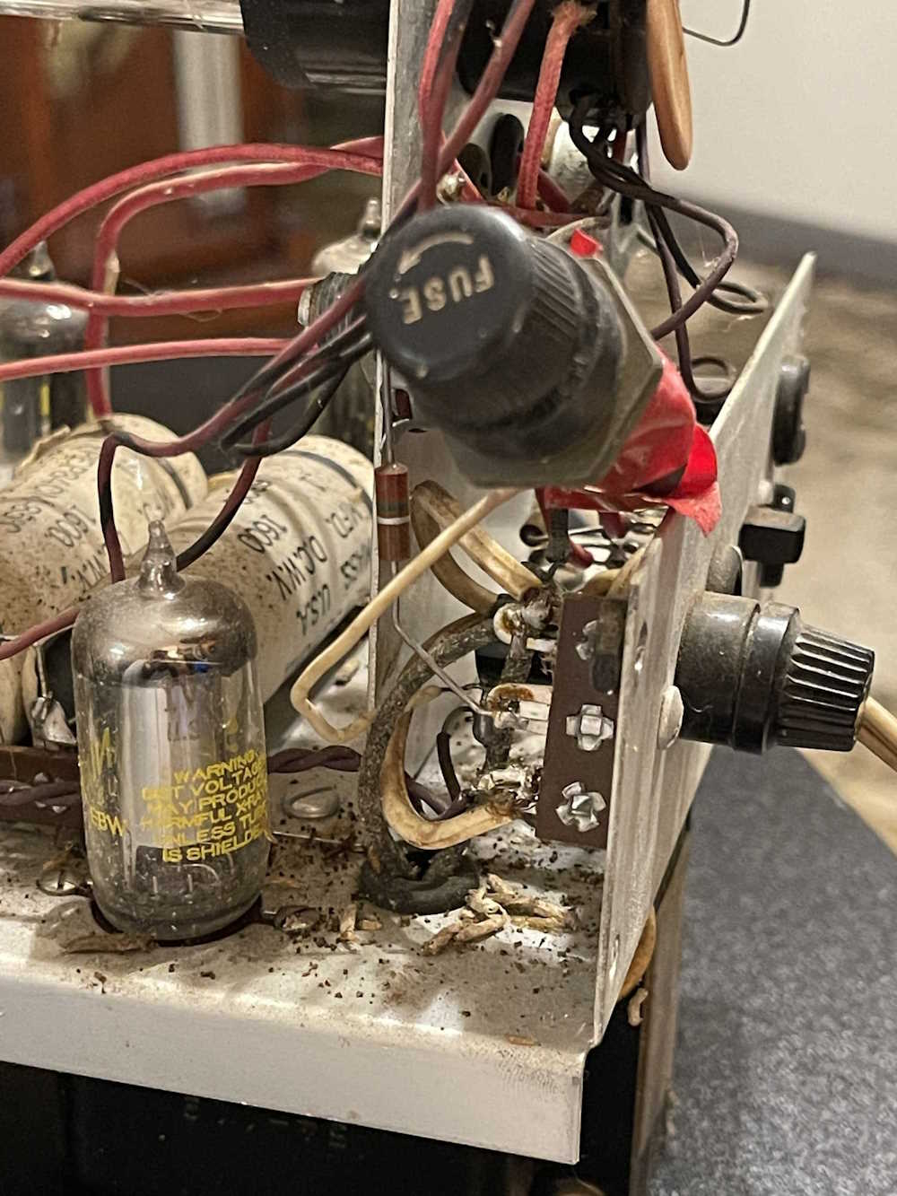
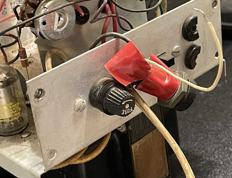
But here’s a thing. The fuseholder was empty. That’s not a good sign, but here’s another fuseholder inside.
It’s not even really soldered, the one wire is just wrapped around the lower terminal of the mounted jack. Wut?
There’s a fuse in it, so I remove the extra fuseholder and put the fuse in the actual holder. Some have suggested that maybe someone was trying to parallel a fuse (maybe…) or didn’t have the correct physical size. Both are 3AG, so that’s not the case. I don’t know what was going on here, but hey - bonus fuseholder.
You’ll also note the large amount of insect debris here. That got a visit from Mister Shop Vac before proceeding.
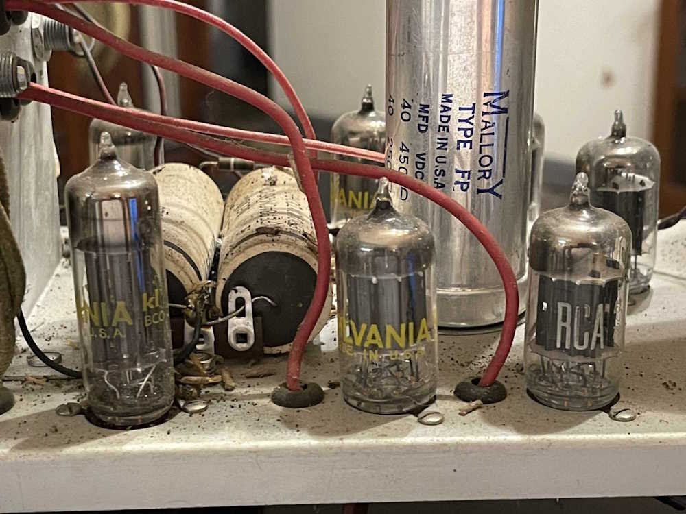
The tube set is a mix of RCA made RCA branded, GE Made Sylvania Branded, and some washed tubes. This probably would have come with Mullard made Heath branded tubes, so this guy has seen a lot of use.
The ones in the back are 12AU7, but have nothing on them. No name, numbers, anything…chances are these came from a bulk reseller that would take used tubes, wash them of any marks, (maybe) test them and then (maybe) rebrand them as their own. That they work is amazing in itself.
Of note here is some capacitors used as filters for the CRT high voltage. 2x 1600V @ 0.01μF are prime candidates for being a Popping Patty, so they’ll need to go even if nothing else is wrong.
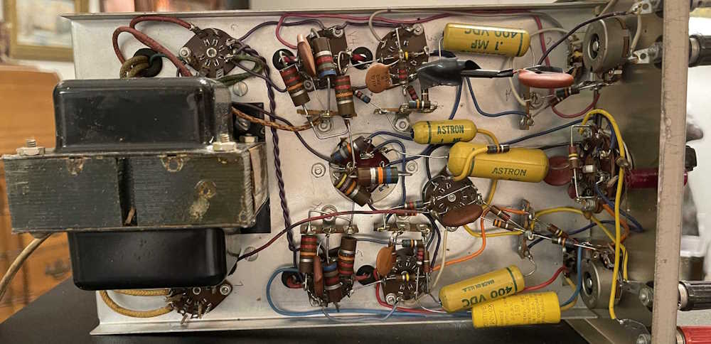
The bottom similarly reveals some capacitors that probably are going to need consideration, but overall it’s nicely built with just one add-in part that I assume was put there by someone other than the original builder.
Does it work? Some basic checks were made and I plugged it in. This device is a 6V parallel string for the tubes, and the 12AU7 are all folded over so they run on 6V. These tubes have their heaters split in the middle so you can operate on 12 or 6V, depending on your application. On almost all of them, only one side lit so a bit of wiggling later (dirty sockets) here comes a trace. It’s about as bright as it was when new, which is to say a bright room washes it out. But it’s there, and that’s the important thing - a dead CRT means a dead unit.
Stay tuned for the next part of this series, some cleanup and basic identification for parts that absolutely need to go.
After digging in to this unit, I determined that it was a basket case. While the unit itself wasn’t baked, the builder most certainly was. Probably less than 1 out of 5 wires in this thing (that weren’t bare interconnects on switches) was soldered securely. The rest? Bad or no solders, wires pulling out of their terminal, no wetting, too much solder, blobs everywhere. Burnt wires, solder drips…you name it. This thing was a how to on how to not solder. I realized that if I wanted to see this thing work reliably, it was going to be a partial rewire.
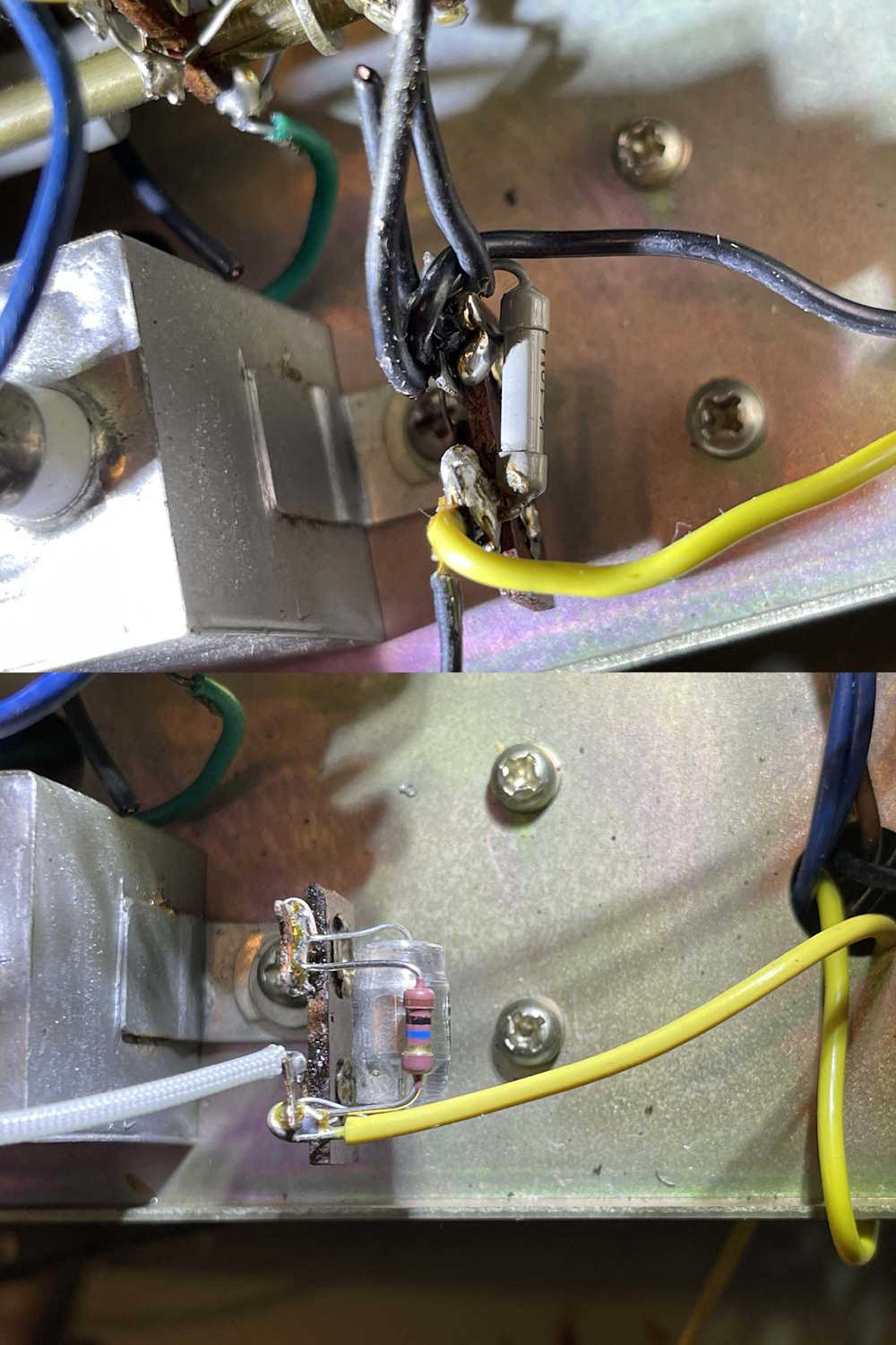
Here are some before and after shots of the cleanup crew’s work:
First is part of the drive for the eye tube. This consists of a capacitor coming in from the terminals on the front, a 1500pF capacitor, and a 10MΩ resistor on a terminal strip…with lots and lots of grounds attempting to terminate here as well.
All of the grounds were removed and single-pointed back to the other side of the chassis. The old parts were replaced with new, high quality parts - the input capacitor went from one of those leaky metal can Japanese parts to a new film cap, the 1500pF ceramic disk (with half it’s coating missing) is now a 600V polystyrene, and the resistor is just a good metal film part. The terminal is now clean with a single wire leading to it. Unfortunately, since the screw for this also holds the 4μF capacitor, I couldn’t solder it down, but it’s tight and clean.
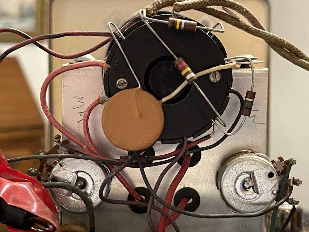
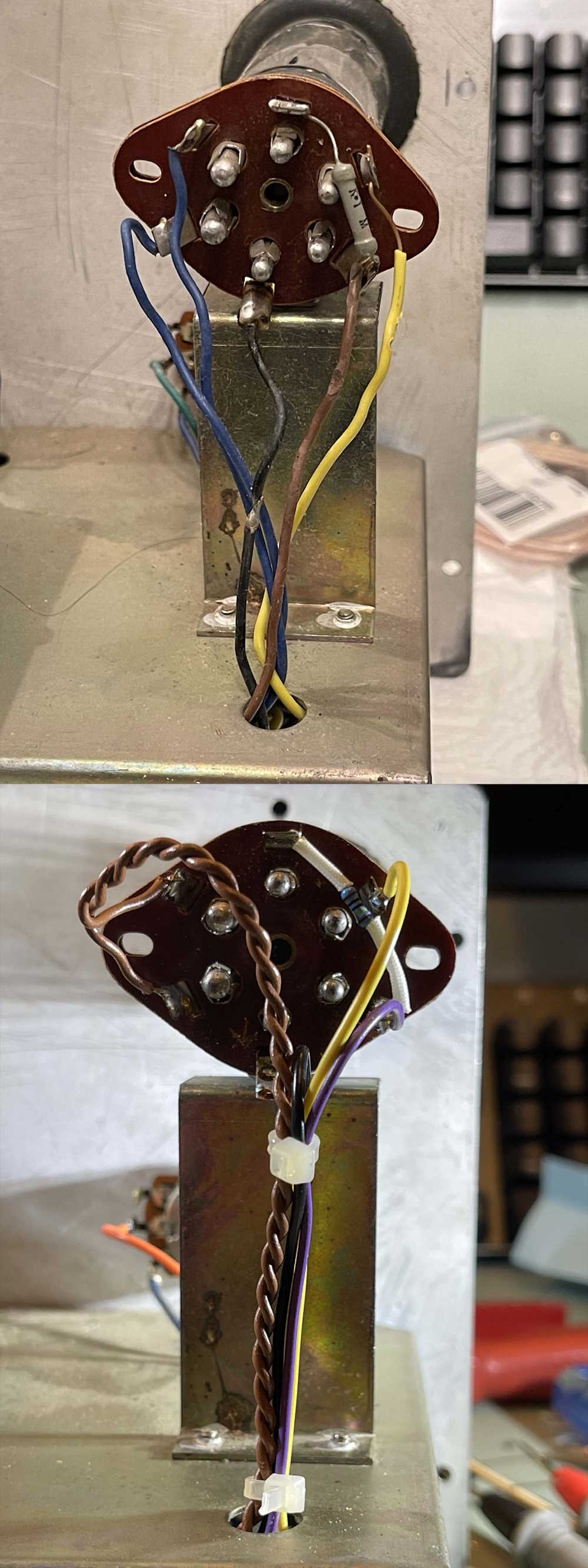
Next is the socket for the eye tube. Almost every wire is burnt in some place, be it here or below the chassis. The black wire is j-hooked together, and the yellow wire has far more exposed copper than is safe. Even the 1MΩ resistor is poorly placed, having too much lead on one side and a “Oops, I cut it too short” lead on the other. Here it was just rewiring everything with fresh wire and properly twisting the filament leads. The resistor now lays in the socket with the proper spaghetti coating.
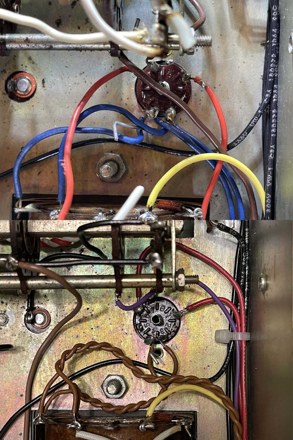
Last is the tube socket for the power supply. This has quite a bit of voltage on it, so it needed cleaned up. Twisted filaments, and fresh wire leading directly out of the socket fixed this one. I admit that the copper is a bit too much, but I’m happy with the results overall. The previous build had some solder balls here, and the fialments were all terminating to this point. I’ll brush this down to get the flux off before final inspection.
Prety much everything except for a couple pieces of coated wire and a couple of capacitors that are still good have been or are being replaced, including the big 500Ω balancing resistor that was flopping around the transformer. Even the AC has been moved off to it’s own isolated terminal strip for ease of disconnect in case of trouble.
I’m waiting on some Blue wire for the measurement section of the device (I’ve tried to keep the original color scheme as much as possible) so hopefully this will be done in a week or so. Stay tuned for the final part of the build, coming soon!
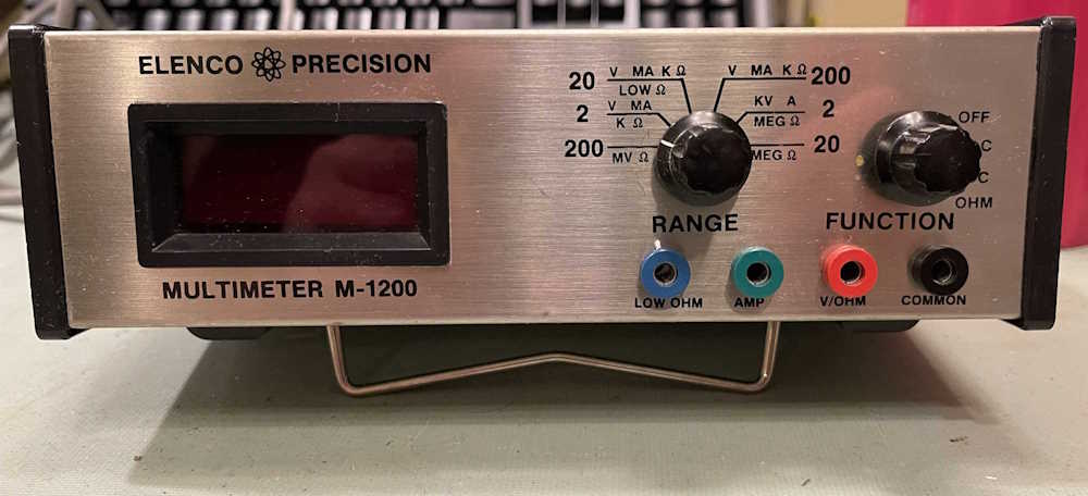
I didn’t need this device, but it came home with me as part of my “Can’t leave the hamfest without a voltmeter” program…It came from Fort Wayne and was a couple of bucks.
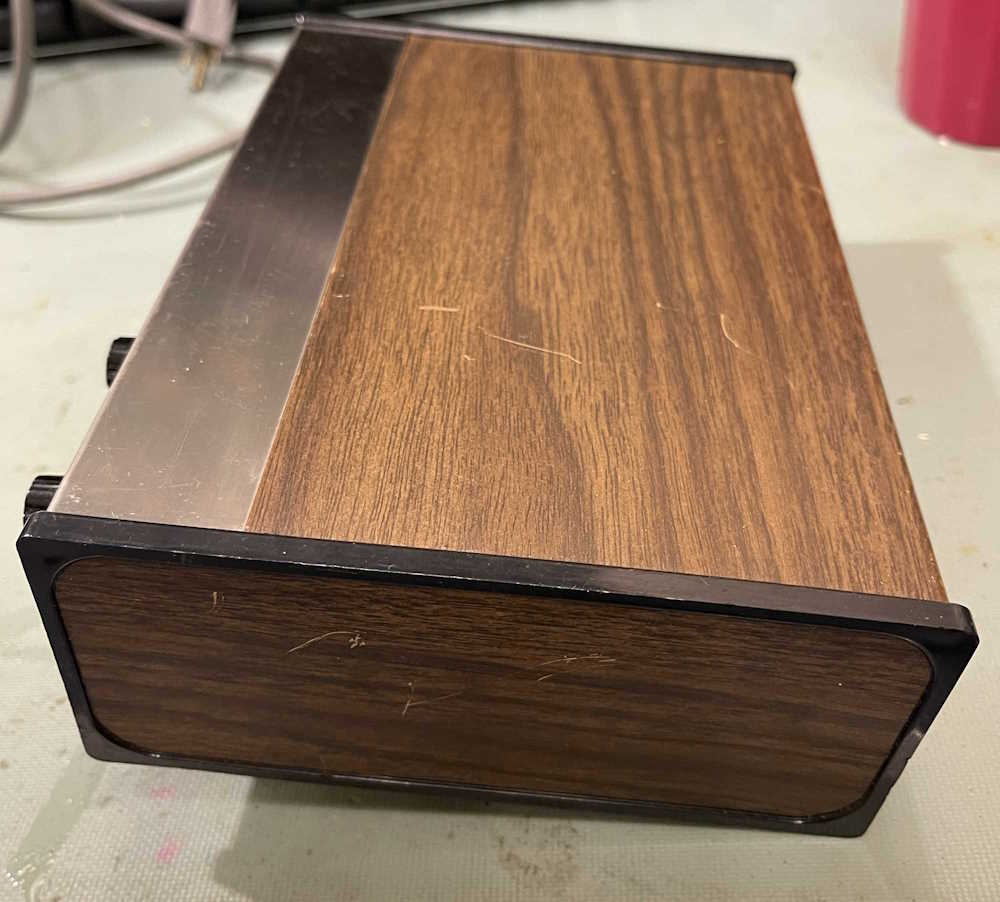
The real reason I picked this up is because of the design. This is so 1970s it hurts, although it probably was made in the 1980s. It’s a simple DMM and offers all of the things you’d need in a meter.
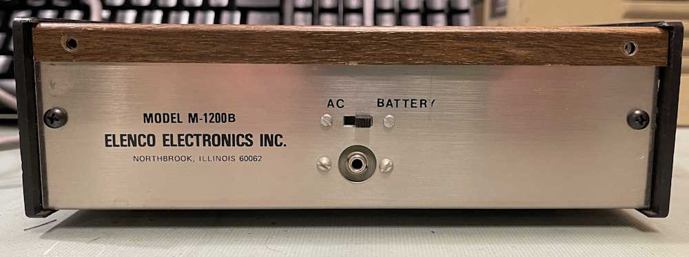
The device can run on batteries or external DC, as evidenced by the back. No mention of the required voltage, however, and the device is old enough that a headphone jack is used instead of coaxial for the power input. Since the device has 4x “C” cell as it’s internal supply, I’d assume the external power should also be 6V.
It’s woodgrain all around.
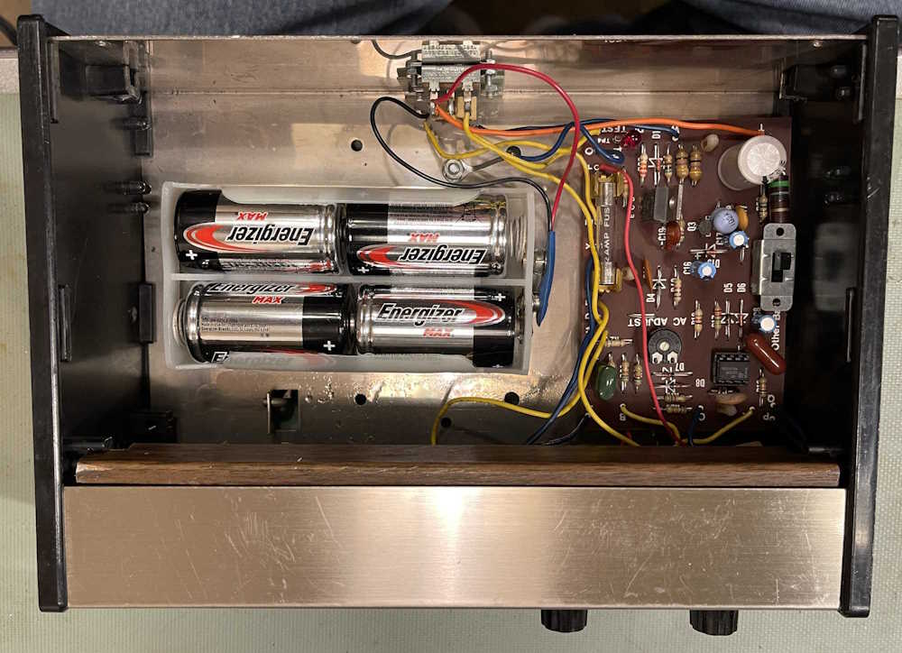
Inside, there’s not much. A power supply board with some circuitry for the meter, batteries, and the business end of the device (under the front panel.) Without the batteries, this thing would be quite light.
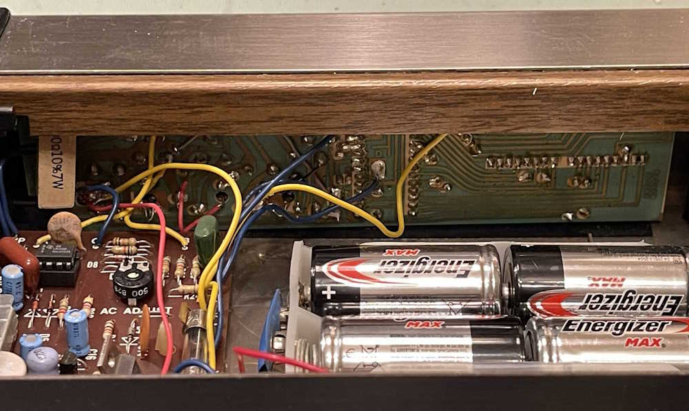
Here’s the main board. It’s most certainly an ICL7117 based device, as evidenced by the big DIP in the middle.
But does it work? I hooked it up to a nearby USB charger device, and it did read - although the decimal point was flaky. I had to wiggle the switch a little to get it to show up. (The 7117 is a simple 3 1/2 count ADC with 7 segment output. It’s up to the user to scale it and provide decimal points.) I didn’t check the unit for accuracy, just operation. I did notice a segment seems to come and go as well, so maybe some solder joints are cracked. Who knows.
What’s going to happen to this? If it’s accurate, it will probably go in my rack as a rail monitor. Otherwise, it’s just a cool piece of old tech.
I have a giant pile of crap that needs to go - probably to Hamvention - but I’ve been giving it away as I find people who are interested. A co-worker had a fake NIXIE clock on his desk, so I asked if he wanted some real stuff. He said yes, and here it is:
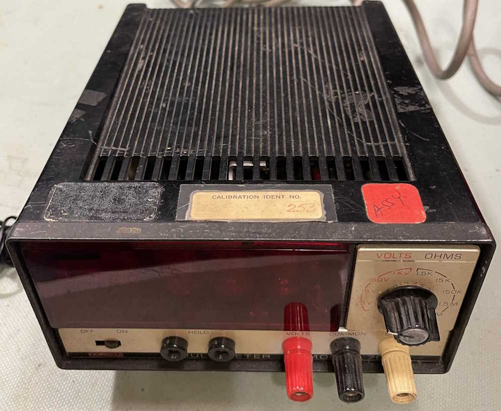
The first is a Fairchild Volt/Ohm meter. It does DC and Ohms. That’s all. It’s intact but rough, and looks like it may have had a handle at one time. Yes, it’s THAT Fairchild.
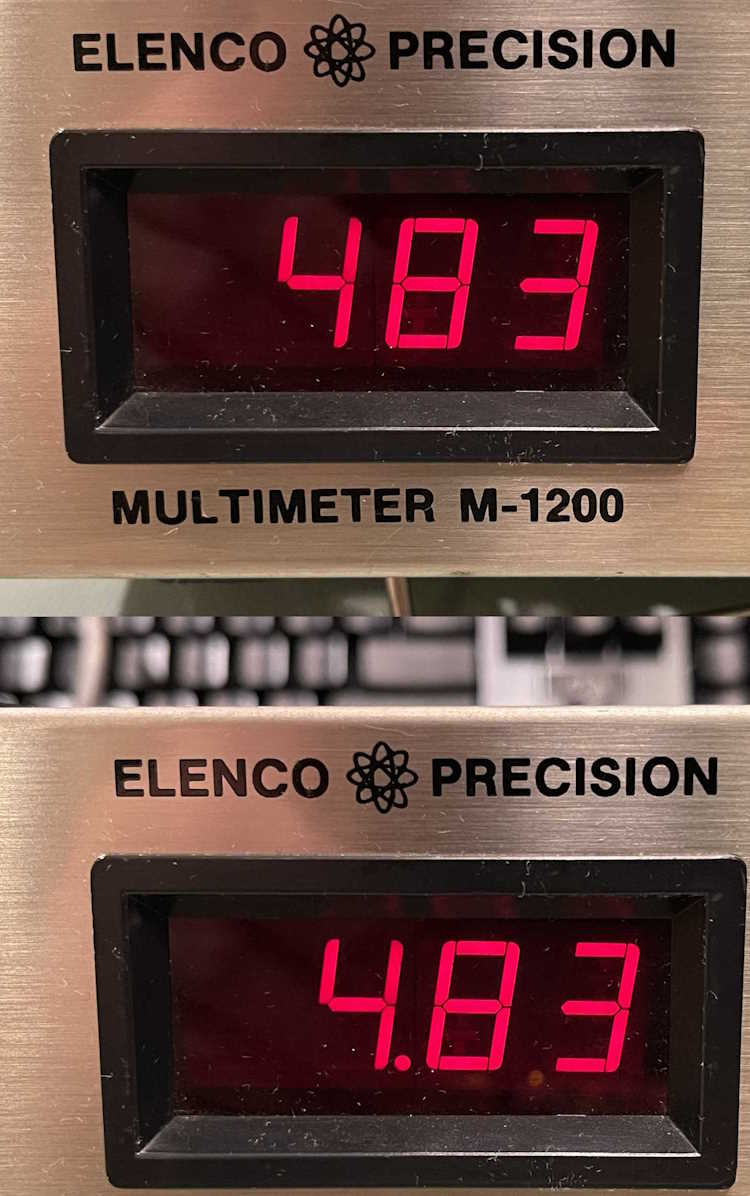
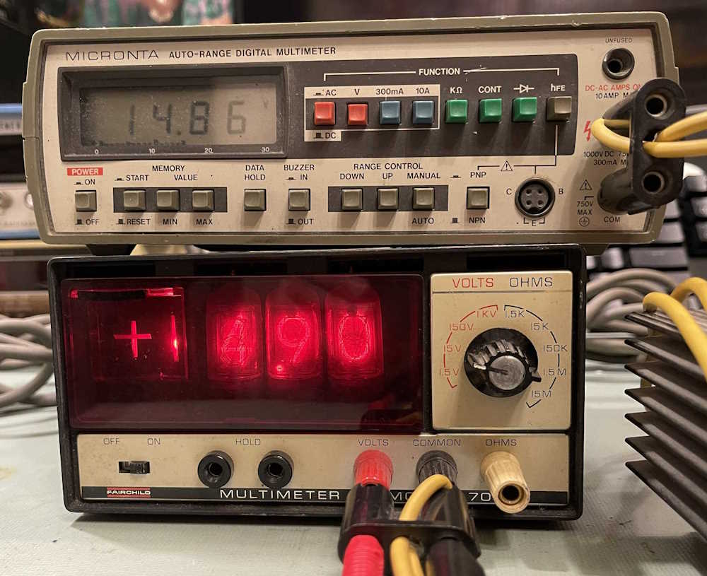
The tubes in this guy are nice and bright, surprising for as poor of condition it’s in. It seems to work, but could use a calibration:
A disagreement of 0.04VDC. Not bad!
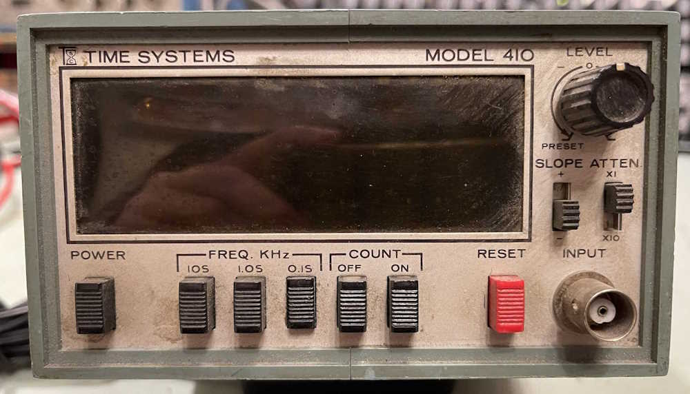
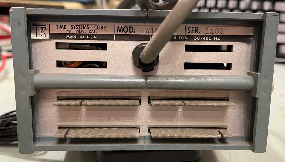
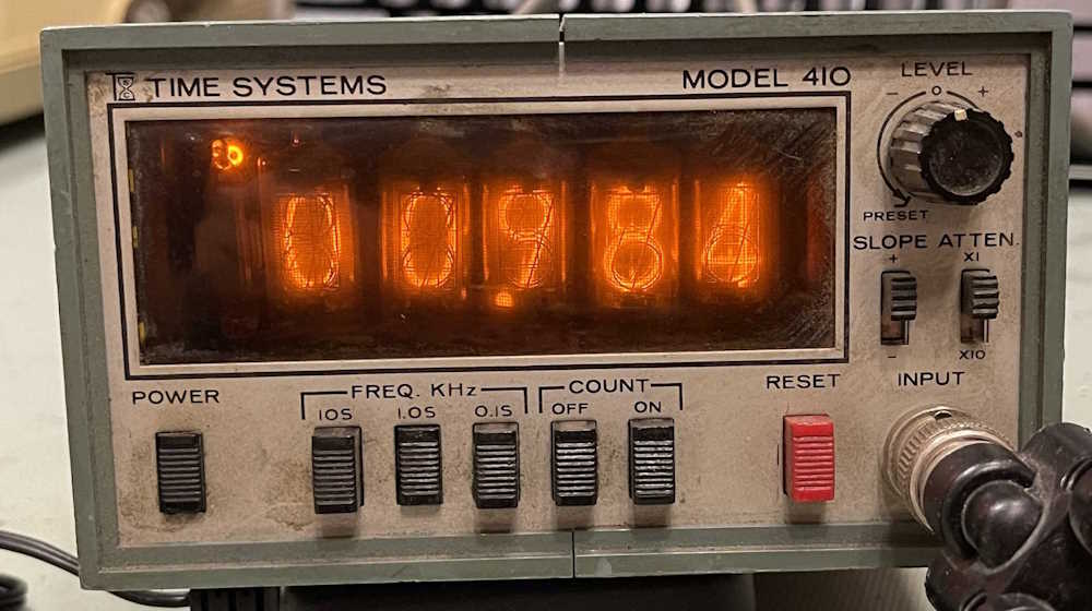
The second piece is a Time Systems counter. This is most certainly a piece of space race equipment put together by a company that sprung up to support the frenzy of the time. It’s a counter/timer with three ranges of measurement.
The back has a bunch of card edges on it. Probably brings out all of the data from the timer, but in what format - who knows.
There’s very little information about this company, and too many businesses today named “Time Systems.” I have to assume they’re like all these little companies from the period - appeared and made some equipment, 10 years later when technology made things cheaper they just kind of faded away.
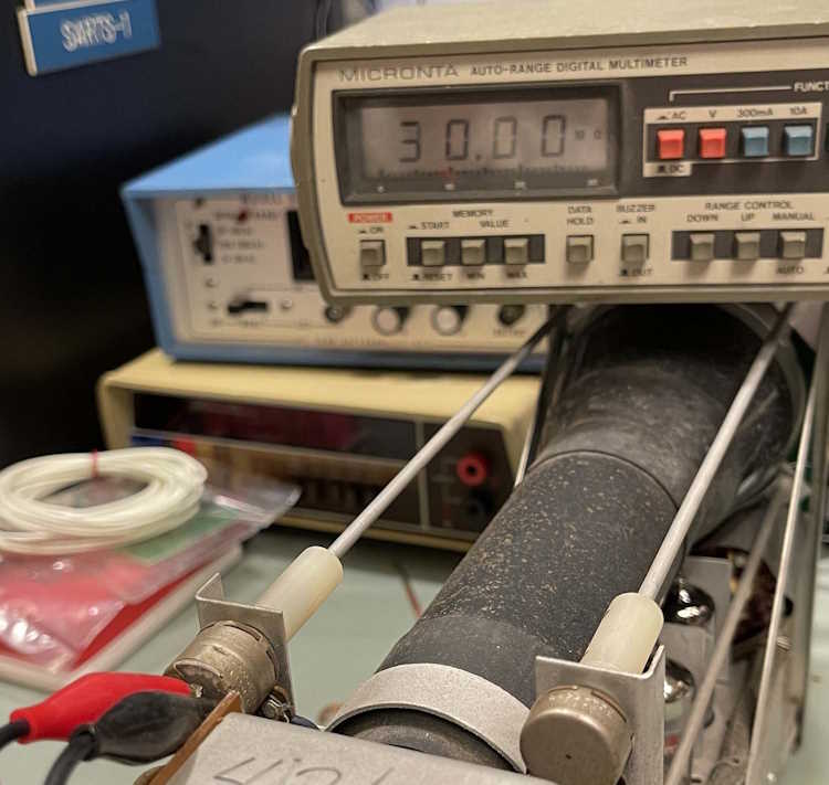
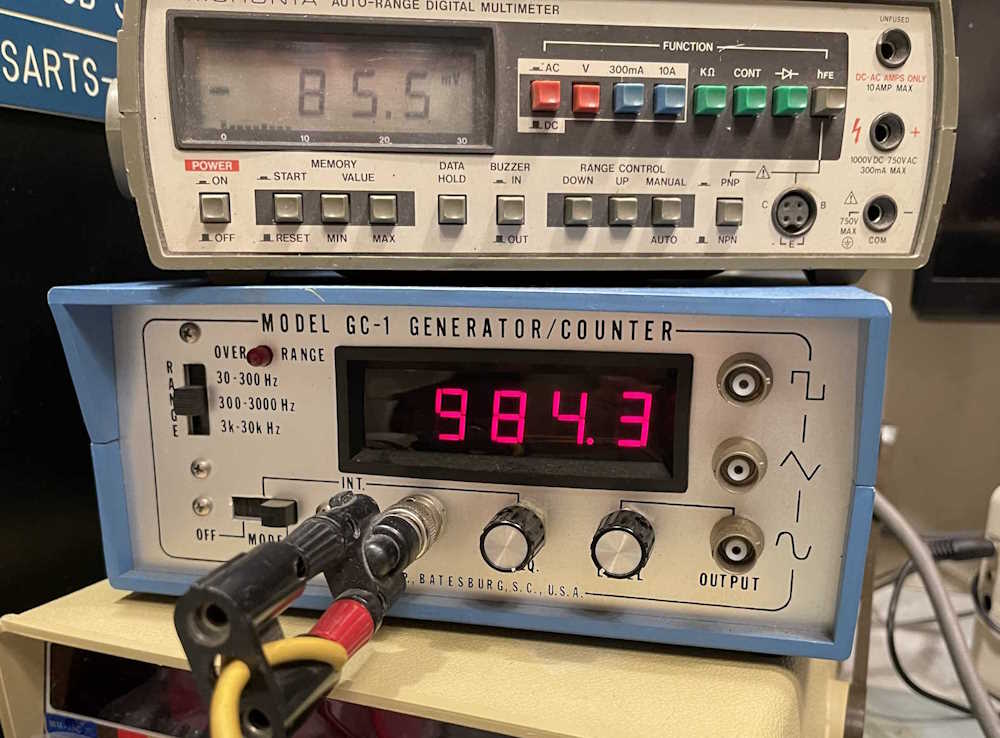
Let’s set the generator to 1kHz and see what this thing does. The switches need a good cleaning, as they need to be wiggled to get the clock to run. The measured value is what I know my signal generator outputs at the given selection, so we’re good.
Testing against my “known” device:
These are off to their new home. Stay tuned for more Junk from the Hamvention Pile, I mean “Projects from the Bottom Drawer!”
Almost all of the parts in the TE-189 C-R analyzer are available, save for the switches and the panel lamp. While the switches would essentially put the unit in the parts bin, other things like the panel lamp can be replaced with something else. It’s just a neon bulb in a package.
The one on my device was long since dead, so I tried to peel the case apart and replace the oddball neon bulb inside with something else. The case plastic was old and crumbly and that went about as well as you’d expect. It didn’t. On the off chance there was something similar out there, I did some searches and ran across the exact part on an auction site. And when I say “exact,” it’s OEM…
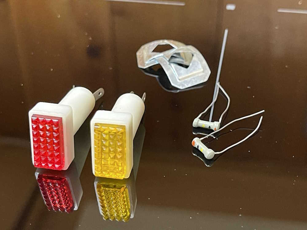
This is a pair of Herald Electronics miniature neon panel lamps. Herald Electronics of Chicago, originally called American Electronic Parts, was a sub-brand of Olson, and as such, one of their suppliers. Olson didn’t publish the fact that they owned this other brand, so Herald was apparently able to sell parts and supplies to other vendors for resale, without incurring the “We don’t want to buy from a competitor” thing you’d get by buying from your competition.
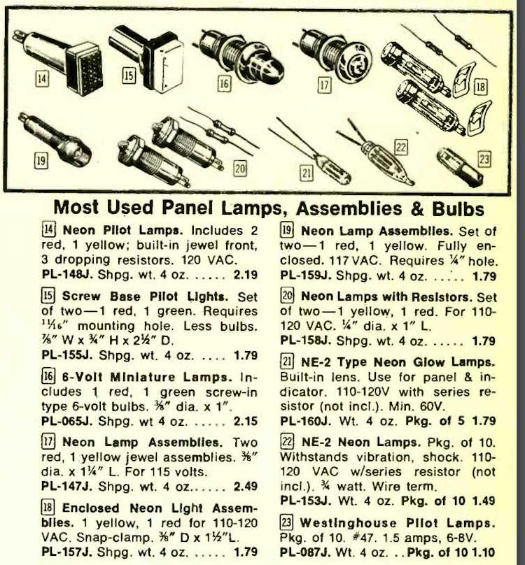
Herald, of course, sourced their product from various Japanese manufacturers, and vanished when Olson did. It was quite the surprise to find these parts, still new. I bought them right away. Here it is in the 1974 Olson Catalog:
There were 3 pieces for $2.19. Figure 14, part number PL-148J. Someone bought a set, used one, and put the rest in a drawer. Fortunate for me!
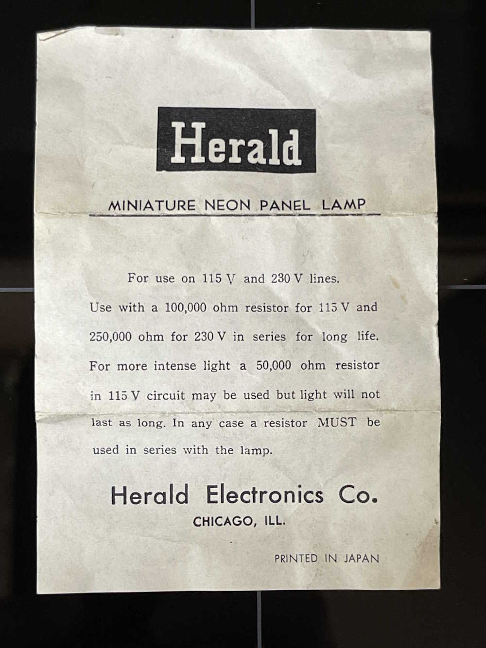
It came with the original pack-in paper pamphlet:
Interesting that the paper specifies a 100k resistor for longer life. The TE-189 has a 50k, so that probably didn’t help the lamp life. I replaced it with a 100k as specified.
The parts themselves are exactly what I needed, down to the little alignment tabs on the bottom. No surprise, they are the exact OEM part. I love the little dogbones they gave with the lamps.
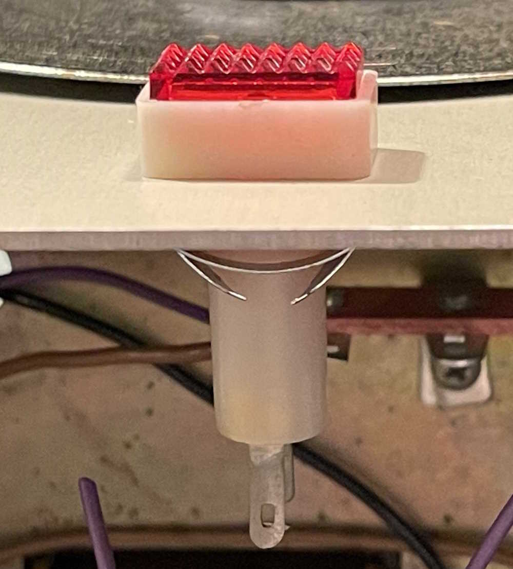
And, of course, it fits in like it was made to be there. Here it is, waiting for wiring in to the panel.
I’m waiting for some wire and a new 500Ω power resistor. The mail is not cooperating right now, so stay tuned!
SO…I thought that the TE-189 job would just be some tidy up and new capacitors. No, that’s not going to work. Turns out that the builder of this device (I hope this was a kit!) managed to get about 50% of the solder joints to hold. The rest were nothing more than burnt wire and insulation, badly wetted connections, and connections that were just kind of wrapped around one another and soldered with prayer.
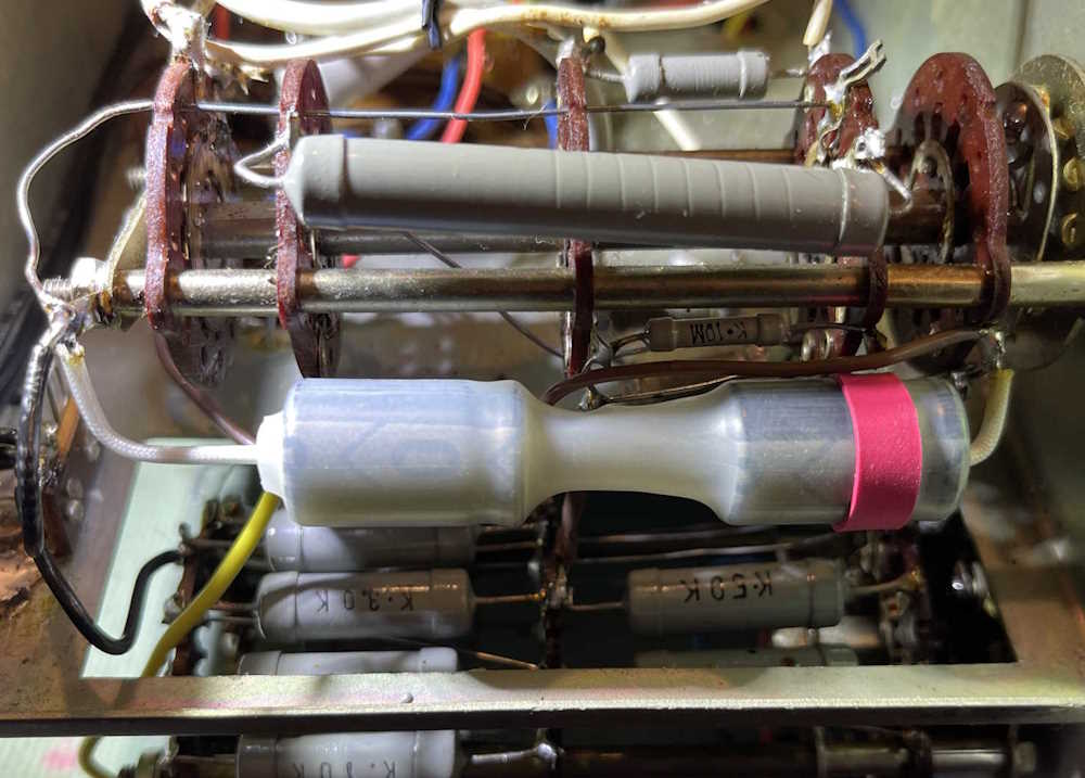
I spent some time last night installing the new filter capacitor. Since a 5μF @ 700VDC is kind of hard to get at a reasonable price, I chose to use two 10μF @ 450VDC instead. These were connected in series to give the requisite capacity at 900VDC. I wrapped them in heatshrink and gave it a red band to identify the positive side of the device. That’s when I started to notice how badly the thing was wired.
You can see a brown wire attached to the same terminal as the positive side of the filter. This wire was just kind of stuck in the solder and came right off when I hit it with the iron. There was enough left that I could cut and strip and insert properly.
The grounds on this thing are a complete mess. A small terminal on the switch had multiple leads inserted in it - rather, attached to it. One was in it. One was wrapped on it. One just kind of hung there. A big blog of solder attempted to hold it all together. Grounds are flying everywhere in this thing instead of coming back to a single point. Plenty of other wires were the same with some just wrapped around other leads and soldered right into the insulation. Even the original filter was a wrap-job and wasn’t wetted properly.
How did this thing even work? Or did it? The neon bulb was dead so it spent some time on during it’s life…
I decided to solder a terminal strip directly to the chassis. Clean and wet the chassis and terminal, and hit it with the 80W iron. I know I’m talking about solder quality, but my 80W device is just not enough for this task. I’ll pick up something bigger this year. It did a (poor looking) job, so all grounds will now come back to this point.
There are around 10-ish ground connections going to all different places in the unit. I’m going to run them back to this double lug so they’re all at the same point. That involves removing a lot of other stuff, including jumpers across the transformer terminals, and a lot of stuff on the other side of the chassis. I’m going to run all of these and then slowly work my way across replacing wires that are in need of replacement. It’s going to be slow going.
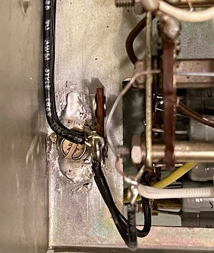
Here’s an example of what I’m seeing - this is the ground for the 450-0-450 portion of the power supply. It was just kind of shoved through a terminal on the transformer and hit with some solder that didn’t really wet the lead. The across the line cap was then wrapped around the lead and soldered without removing any insulation - the capacitor just kind of melted into the plastic and didn’t really wet. It all goes away.
There’s a big lump of grounds just to the right of this that I’ll correct, and then start replacing capacitors and fixing the tube socket and the HV power supply.