I hope that 2025 was good to you, and I hope you found something here on projects that caught your interest. I have a number of devices lined up for the coming months, and there’s plenty of hamfests on the way.
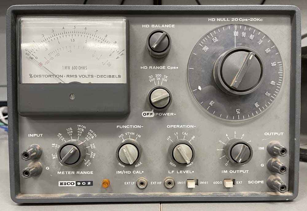
While the Hallicrafters S-38C is waiting for a check before plugging it in, I’m starting on this analyzer. This is a standard null-type analyzer of a nature similar to many others. You input a frequency, null out the fundamental, and what’s left is the distortion. It’s spat out on a meter and scope terminals.
These devices seem to go for a lot of money, so I was quite surprised to be able to pick it up at Dayton 2025 for $30. I believe the gentleman I purchased it from was the original owner, and the device appears to have been factory built.
It’s in need of a cleaning:
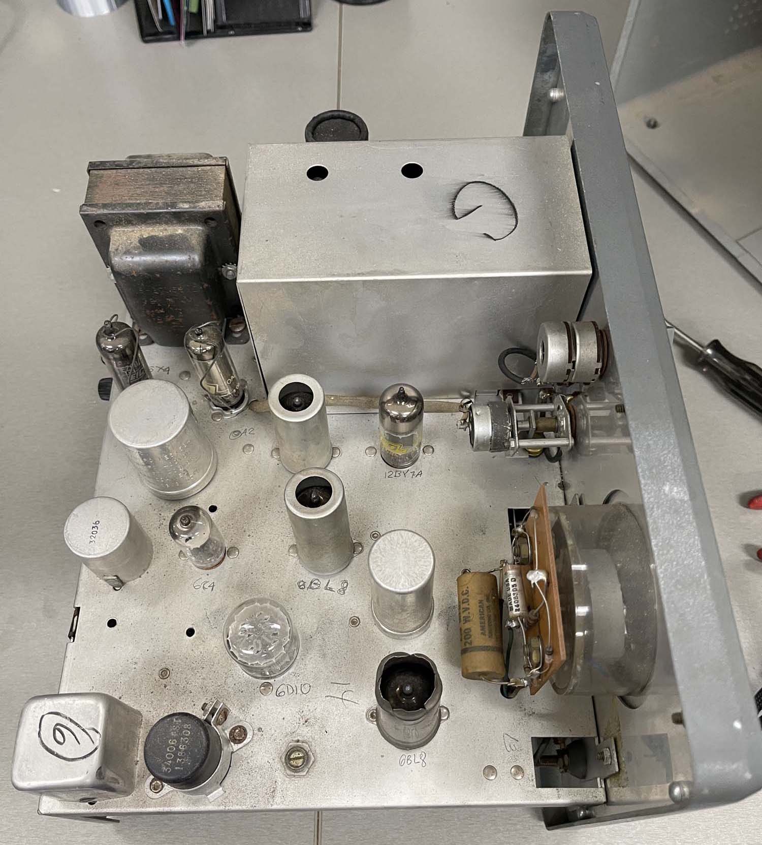
Inside it’s dusty but relatively clean. A little rust on the transformer.
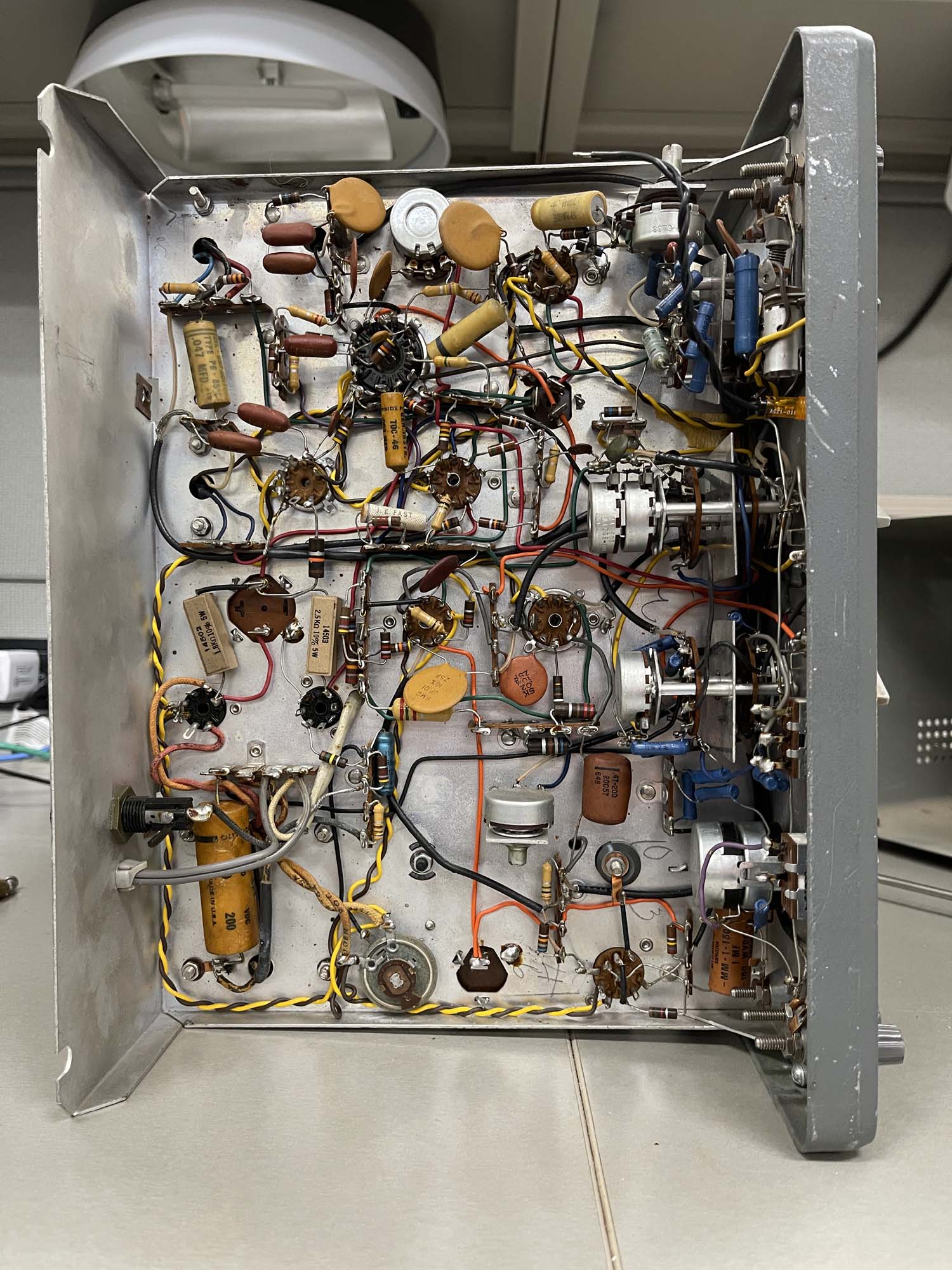
And the bottom is nice and clean and shows almost no trace of work.
The only imperfection I can see is this little wire snip, and I’d say that was left from the original build.
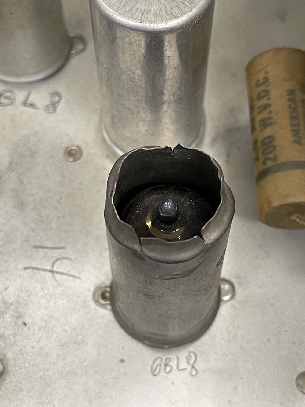
The top has one modification, someone cut open a tube shield. It was suggested that perhaps this tube ran hot and was not operating properly (thus the blackened metal,) and this was an attempt to make it work. Rather crude, and I may see if I can get a new shield and see what happens. If this is indeed an issue, I’ll cut the top to be a bit more clean than this let’s just chop-job it.
So, it’s in great shape. There’s some wax paper capacitors that will need changed, but it’s good enough to try out. First thing, is it needs a new cord. The original is barely hanging on at the input to the chassis, so it gets a new polarized cord. It also needs a pilot bulb lens, but I have some other lamps that may fit here. Fuse is present and not blown, but the glass is cracked, so that’s changed out. Plug in, and…
Nothing.
Turns out the power switch is completely open.
I only had one jumper with me, and it was in use as a temporary fuse. So, I decided to call it until I could get a proper fuse in the unit, at which point I’ll jumper the switch temporarily.
It looks like I can get this component apart to see what’s wrong, so I may do that in the near future. Stay tuned!
This will be near to the last post of the year here on projects, and it’s something to browse while you’re waiting for the new year holiday to start. I found out earlier this year that you can reference galleries from different points within this blogging system, and thought it would be cool to have a year-end page with all of the stuff I saw at hamfests. So…here it is! The only ones that won’t be presented in that manner is the SCARF show in May and the Central PA hamfest - both of those because there were very few pictures. They’ll be links instead.
Without further ado, here is the stuff I saw this year at hamfests:
.
The Sunday Creek ARF Hamfest, Shade Ohio.
A bunch of old-school test equipment.
That 1970s blue.
Still a lot of AM CB stuff.
A big, old, Heathkit power supply.
How big can you make a 5W CB?
I didn't buy a voltmeter this time!
.
The Cuyahoga Falls ARC Hamfest, Cuyahoga Falls Ohio.
A nice AOR scanner with a serial control port.
A table full of audio related stuff.
BetaMax anyone?
A giant broadcast tube.
A small capacitor checker. This went home with me.
Some cool 1970s cases. I took a woodgrain special home.
Someone had a collection of early music video.
A lot of radios and tubes.
The club has a table of cheap stuff.
A coffin set. These have become cheap.
The inside of the coffin set.
Another coffin set.
Another coffin set. Would have got this if I had room.
I bet this thing can't hear WLW next to the tower.
A giant-size signal generator.
Some radios and one of those monitor scopes.
Self explanatory.
Some old Heath stuff. Some of it's not all that useful these days.
Another small Heath scope. Took this one home, it's in great shape.
Dad's homebrew projects.
Knobs. Need I say more?
I wonder who Lafayette was channeling here?
The last Heathkit of it's type.
Who didn't have one of these?
A stack of old meters.
An old mill controller.
How many of these were made?
A nice National radio.
Pulse generators.
Various rackmount equipment.
Surprise, radios!
Even more radios.
You guessed it, radios!
You'd think this was a radio show.
An “Electric Eye” science kit.
A nice old Solar cap checker with a meter instead of an eye.
I couldn't pass this up for $5.
I see you hiding in there.
A lot of different equipment.
Just some stuff. There was a calibrator here I took with me.
I wanted the triple stack, but we couldn't come to a bargain.
A television test jig and degaussing coil.
Some oddball one-off set made in the 1970s in the USA.
I love that they used a lot of color on these.
.
The TUSCO Hamfest, New Philadelphia Ohio.
Some interesting equipment. Radio gear?
Lots of vidicon tubes. Lots and lots and lots!
The early 80s still live among us.
A dual band (lol!) Lafayette Radio.
I bet you never thought you'd see more radios.
AM/FM/8-Track with a cool honeycomb face.
Radio Shack ghosts haunt us.
A couple of old Tek (tube-type) scopes. Ok price.
A mini scope. That seems high priced.
Just stuff from the CFARC guys. I took the decade box.
.
The Athens County ARA Hamfest, Athens Ohio.
CD-R…once a miracle, now just junque.
The camera doesn't do the chrome justice.
An interesting passthrough counter.
A desoldering iron from the tube socket era.
An all-in-one RF test station.
Some older test gear including a cap checker in the box.
An HP 200 series generator and an old tape player.
A “Portable” multimeter.
Once of those tube unit power supplies.
An old Sony reel-to-reel tape player.
A couple of scopes. Interesting, but not needed.
An interesting Sencore tube tester.
Radios and an overpriced PACO tube tester.
A bad shot of some old gear. Would have taken the rightmost one if it had been in better shape.
One of Trio's active panel meters.
One of Heathkit's interesting lunchbox tube testers.
Some radio tuning gear.
.
The Dayton Hamvention, Xenia Ohio.
Friday:
I used to work for this toxic company.
Some big rackmount amps.
Somoe old Motorola comm analyzers.
A cool looking antenna controller.
A stack of audio gear.
A cool old blue B&H oscilloscope.
Lots of parts.
Stuff is just laid out on whatever.
It's chrome plated!
Lots of walkies.
A table full of consumer era radios.
One of those high-precision Regency counters.
Someone bought a box of CRTs and related materials.
A nice Heathkit decade box. Took this home.
A dirty Hallicrafters.
Not going to break this one.
Hard to believe it's only 1.7GB.
A giant dummy load. Dummy not included.
A nice Eico harmonic distortion analyzer. Went home as a project piece.
The accompanying Eico RF generator.
An Eico scope. Tempting, but I have too many scopes.
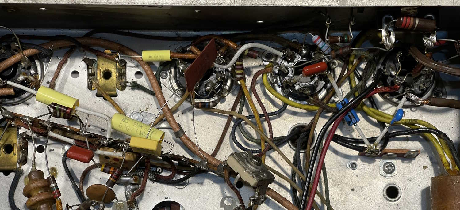
Working inside a wild chassis is always an exercise in delicate maneuvers…you have to get in to places without burning or breaking other components that might be unreplaceable. I’ve spent a few hours replacing the paper capacitors in this Hallicrafters S-38C. At least, the ones I know of, some of the postage stamps might also be paper…but the majority of the problem devices are gone, modern parts in their place.
This one has been a bit different. For most of my projects, I’ve been gutting the chassis and starting over. Not here - the old stuff must remain because this is a more complex device with a lot of inductors and adjustable capacitors for the various frequency bands. I did take the time to move some of the parts to more convenient locales, however - mostly necessity as some of the new ones don’t reach as far as the old ones did.
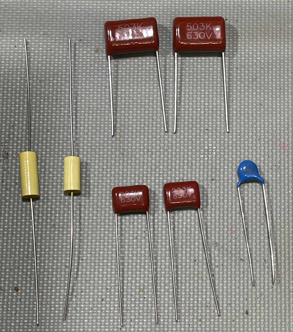
I did choose some different parts after studying where they actually lay in the circuit. The yellow boxy part and the blue drop are both safety capacitors, chosen because these tie the line to various points like power and chassis ground. The remaining parts are regular film devices.
I haven’t soldered everything yet, I want to give it a final look over with schematic in hand. But, another hour or so, and this device is ready to play once more. Well, at least some of the local AM stuff, there’s just not much on SW these days that this thing can hear.
Time to clean the wax off my fingers and pull the schematics, and then clean the wax off of the new parts. That stuff gets everywhere!
In the last installment, we talked about getting parts for the Hallicrafters S-38C. Justradios.com comes through again with values marked per the schematic.
I have exact values as per the schematic, not that it really matters too much. But, if you can get them, why not?
2 x 0.05μF
2 x 0.02μF
1 x 0.01μF
1 x 0.002μF
and
1 x 0.022 for the across-the-line capactitor.
I’ll probably get to this in a couple of weeks, as there’s some holiday prep that needs to be accomplished this weekend.
Mail-order tickets for the 2026 Dayton Hamvention are now available. It’s the same price as last year - $26 for all three days, and this is a discount over window price. They’re generally available until the end of April. After that, they start getting held will-call for pickup day of show.
This is the premier event of it’s type, and for the longest time when I only had one slot available for shows it’s the one I chose to go to.
Dayton Hamvention 2026
Greene County Fair and Expo Center - The Whole Thing
210 Fairground Road
Xenia, OH 45385
May 18 19 20
Hours vary by day, opens at 9AM
https://hamvention.org
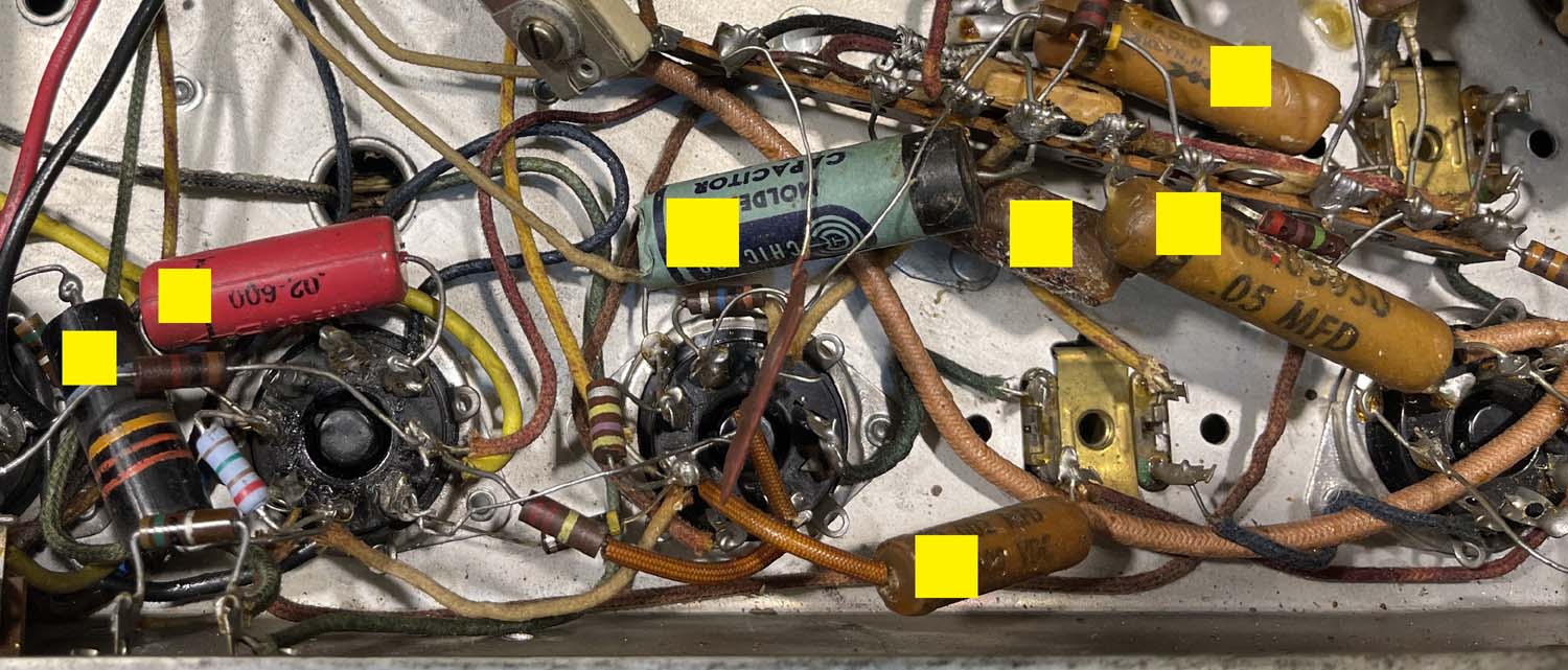
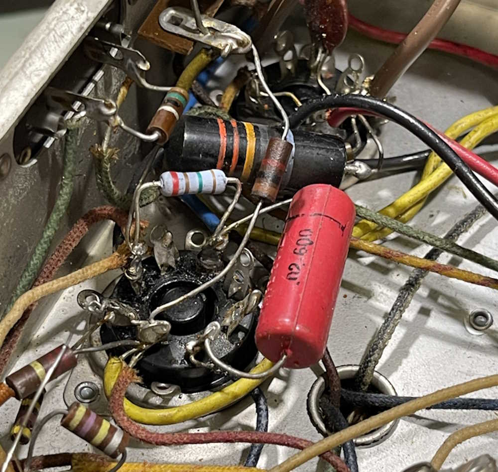
I’m only going to replace the leaky capacitors on this unit, so I’ve identified the following parts:
All of the parts marked with a yellow rectangle need to go. These are probably leaky enough that they could potentially cause issues with the device, and that black bumblebee part is a known problematic unit.
I’m going to order these pars if I don’t have them in stock, all @ 630V except the across-the-line ‘bee. Those have their own ratings, and I have plenty in stock.
2 x 0.05μF
2 x 0.02μF
1 x 0.01μF
1 x 0.002μF
I’ll probably just order my standard yellow films unless I can get a good deal on another type.
Edit: I got a good deal on some other types from justradios.com.
Stay tuned, there will probably be another post or two before we wrap up 2025!
Last year at Dayton, I had purchased an S-38C because I wanted another example, having had one when I was younger. Unfortunately, while I found one, it seems to have silver-mica disease. Really, really bad. So the hunt was on for another one.
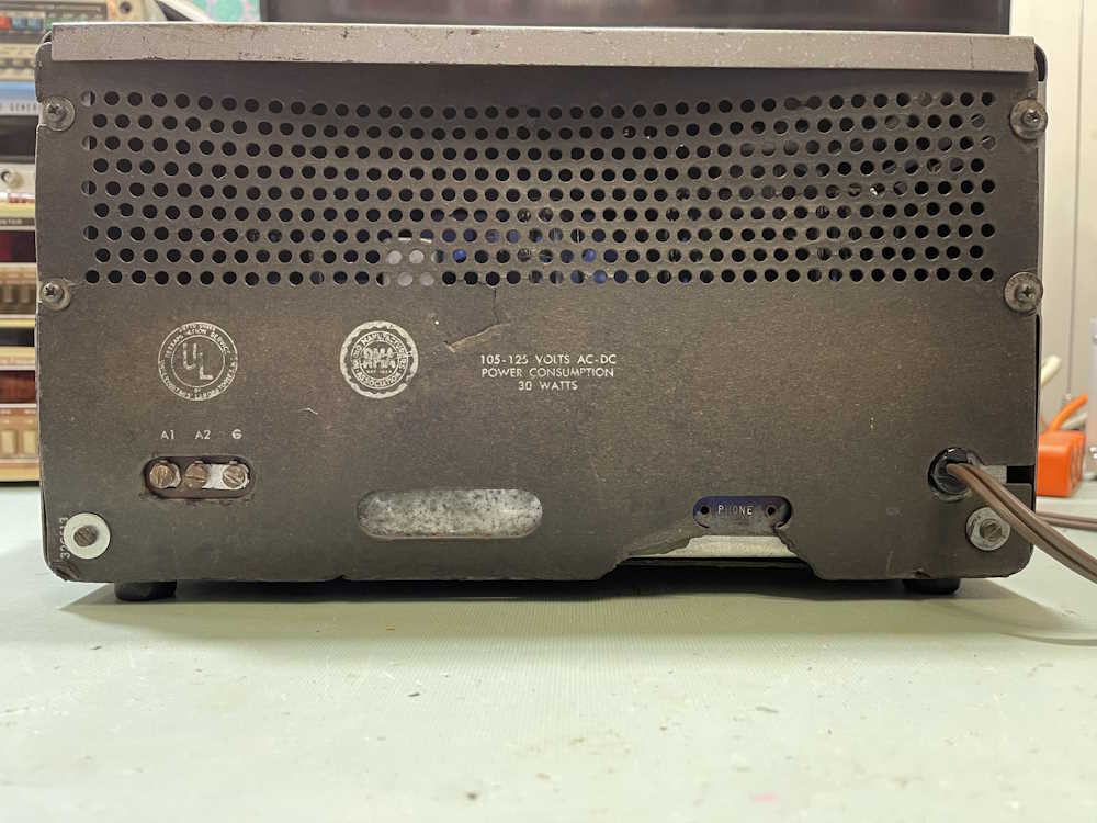
I found this one at Findlay 2025:
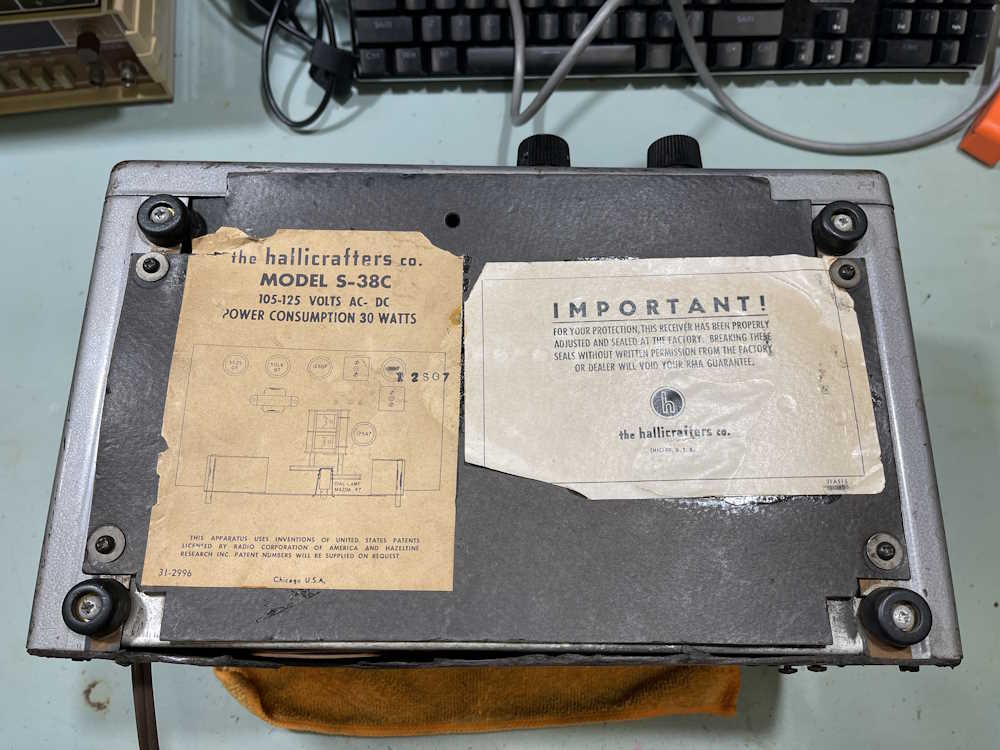
It’s in decent enough shape. Back and bottom covers are present, even though the paper is deteriorating.
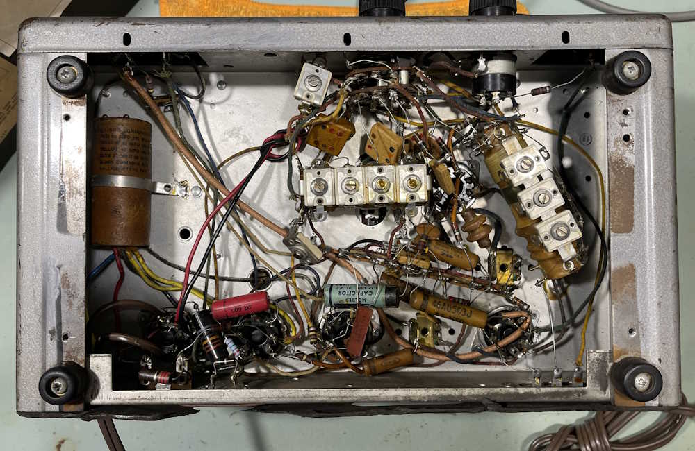
Inside, it shows a little work. Some new resistors, a filter that’s been resoldered, and a new power cord.
I’m going to replace the 6 tubular capacitors in this one so it’s somewhat safe to use. Of biggest concern, of course, is the bumblebomb present across the line. That absolutely must go.
Other than that, the filter is in good shape, so it stays for now.
Stay tuned for the next part of this series where we determine what parts we actually need!
I’ve been posting blog links to a federated social network called Nostr. This was mostly to drive traffic here, but I’d reply to anything that was sent to me that was not obvious spam. I’ve written about that in a couple of past posts:
One of the reasons I chose the site I did was because it supported a feature of Nostr called “communities” - that’s exactly what it sounds like. A basic forum with a title and a common theme. I created /oldtech, a place for stuff like what I talk about here. While I never really got any other posts in the community, I did collect the usual spam.
Spam is a big problem on the Nostr network communities. There’s no good way to manage it, and the more popular you are the more you’ll get the standard Indian scams, crypto crap, and just general-purpose canned ham. You either approve it to show in the community, or you ignore it and it sits there in your inbox forever, waiting for you to approve it. In that regard, spam is very hard to control on Nostr, and it makes the communities messy.
Today I tried to make my usual Monday morning post and found that the site owner had removed communities in favor of a single feed of posts. The reason was that communities were “messy.” I fully understand this reasoning as there’s zero garbage control. Some of the communities I looked at had hundreds of pending spam messages in their box. (You can see pending messages, they just don’t show up in the regular feed.)
I kind of stepped back from this for a while, but I’ve started posting again seeing as how all of my old posts are there - they just aren’t in a community now.
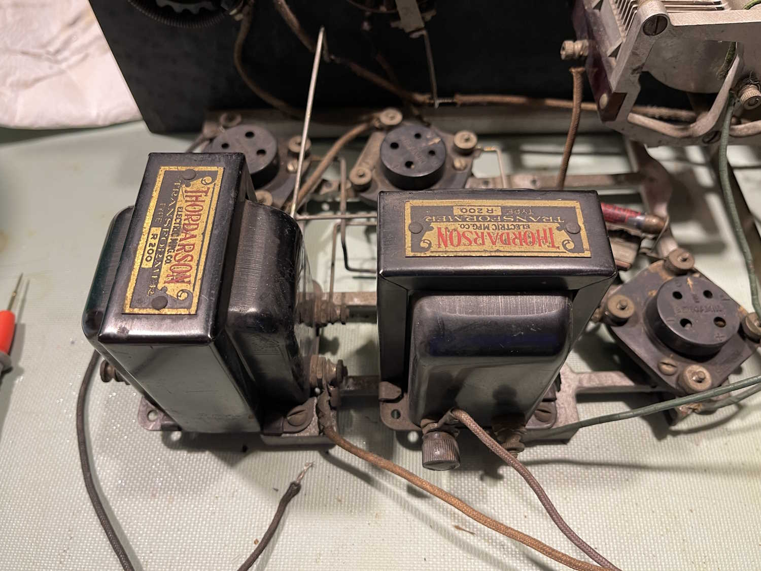
In the last part, we identified where the power connects. This part is about checking coils and transformers to identify any problem areas.
And…there’s a problem. The AF output transformer is open on the side that supplies the plate voltages. This is the leftmost transformer in the image.
While the Thordarson R-200 transformer was a common part for this type of radio, and they are out there in resale land…good examples can go for a bunchabuxx. Bad examples can still be somewhat expensive.
For now, this project stops. I’m not willing to invest a lot of money into what would ultimately be a gee-whiz device. I’ve whittled options down to these:
1: Find a transformer at a show. Perhaps Dayton or Cuyahoga Falls will have one at a reasonable price.
2: Try to open this one up without damaging the crimp ears that keep the mounting plate on the body.
3: Donate it to the Early Television Museum’s operating funds auction in the fall.
I’m thinking #3 is going to be the winner here, as I have plenty of other devices to work on. Stay tuned, this may yet show up in a future post.


 Lafayette Radio.")


 scopes. Ok price.")


 radios, not as many as previous years.")


 radios.")


 Silvertone Battery Checker.")


")


 future!")