- 2025
- Jan
- 2
The Heatkit AF-1 Analog Frequency Meter, Part 2 - Testing.
In the last part, we checked out the Heathkit AF-1 Frequency Meter and found that, at minimum, the power supply filter was bad.
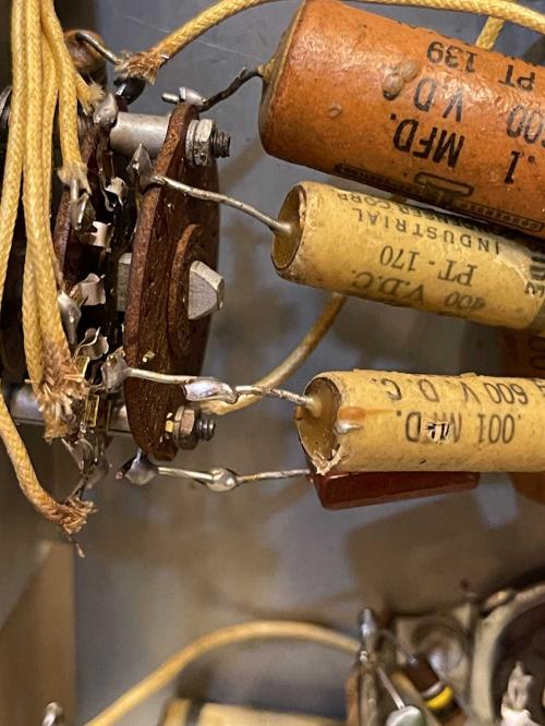
This isn’t necessarily a virgin unit, as evidenced by the different styles of potentiometer in the thing. There’s other evidence, including things like these j-hooked capacitors on the range switch.
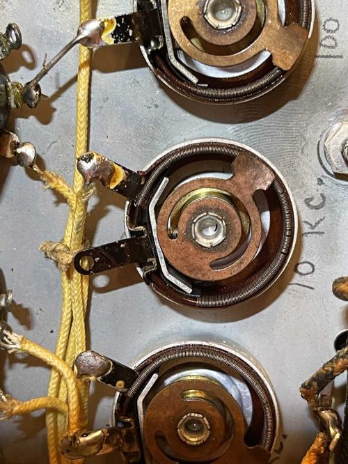
The original rheostats are kind of unique here. You can see that there’s one lead left unhooked on this device:
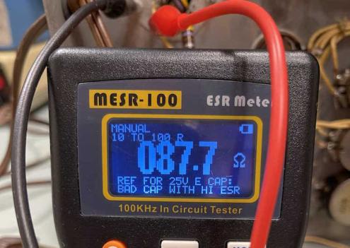
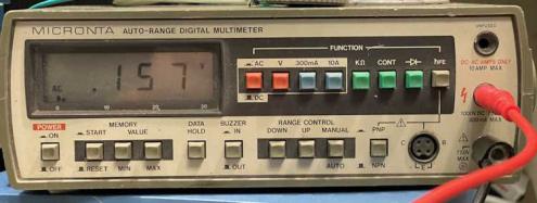
That threw me for a minute, but a quick probe revealed that one side is tied directly to ground. But we’re not here to look at the design choices of yesterday, we need to see what’s bad now. Probing the filter capacitors with an ESR meter revealed that they’re either high ESR, or completely open and I’m just getting pure resistance from somewhere else in the circuit:
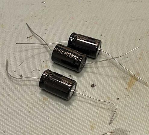
They’re not shorted, so we can just parallel some parts across it. I have some random 10μF caps laying around, and at 450VDC they’re more than enough for this device. As an aside, the schematic I have specifies 20μF, but that appears to have been a pre-print schematic. I have a manual ordered since I wasn’t able to find one online, so we’ll see what that says.
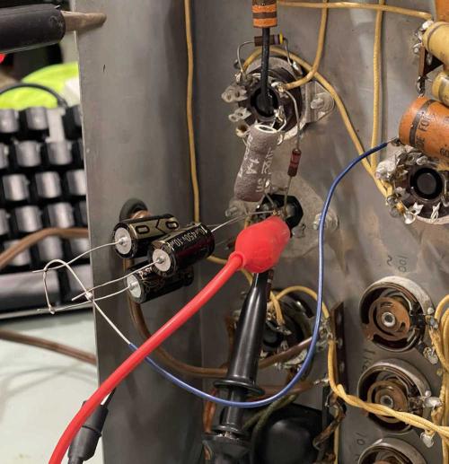
Installing them was just tacking them in and running a ground:
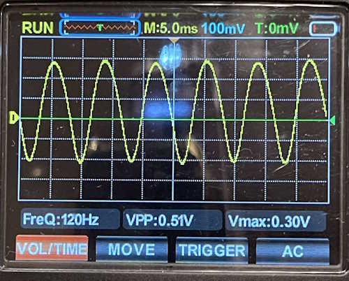
That calmed the ripple down a lot.
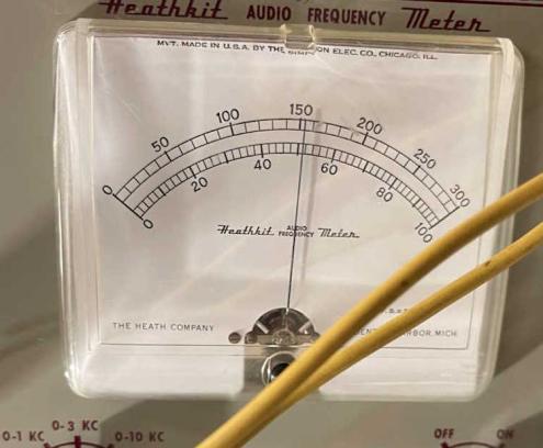
Still is way off in measurement, however.
It’s still giving me the same reading as before. While I was able to dial it in somewhat, it’s not accurate. Well, it’s not as accurate as it should be, so all of the capacitors and probably resistors should be replaced.
There’s no assembly instructions for this device, as it was sold as an “advanced kit.” No big deal, it’s simple enough to build from the schematic. Off to Mouser for parts!
Next part of this series: https://wereboar.com … hematic-corrections/
Previous part of this series: https://wereboar.com … quency-meter-part-1/
