A Viz WP-705 Power Supply part 3: Troubleshooting in stages.
Wednesday, October 22, 2025 at 10:34:32
In part 2, we discovered that the 5V rail for the display was bad. At this point, I decided to pull the regulator out and see what was going on. I wanted to get a manual and find some LM309H spares before going further than part removal, and I found both.
The manual, unfortunately, wasn’t helpful, as it was for the wrong revision of device. I found some LM309H regulators, so off we go.
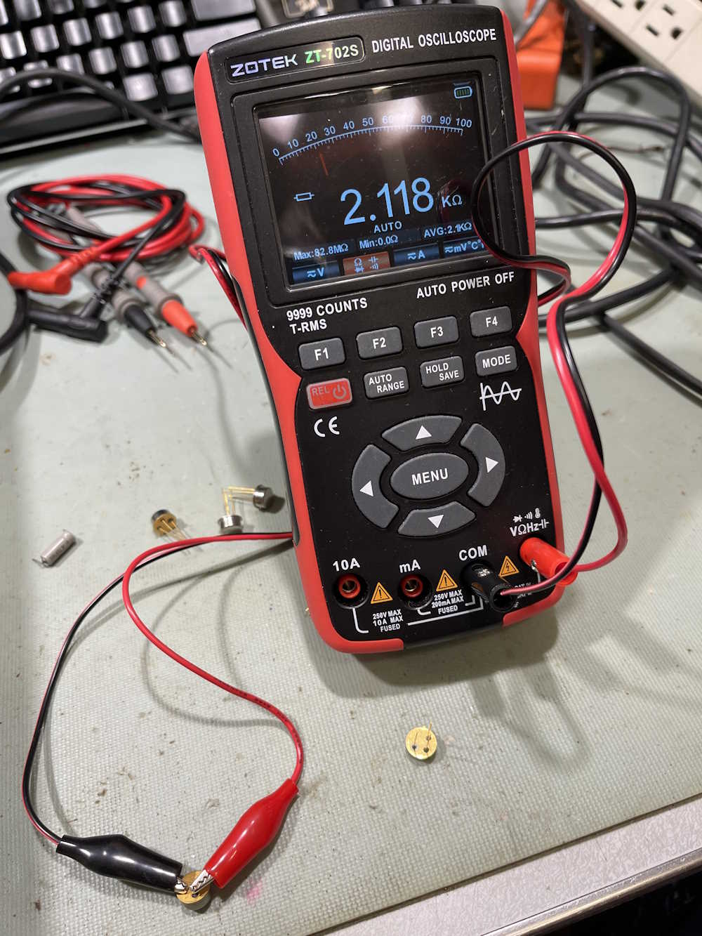
I started by measuring the regulator itself with a simple ohms test. The part I have read 2KΩ from terminals to ground, and that’s not right. A new part reads about 30MΩ to ground from each terminal, so the part in the unit is defective, and is probably causing the output voltage to be low.
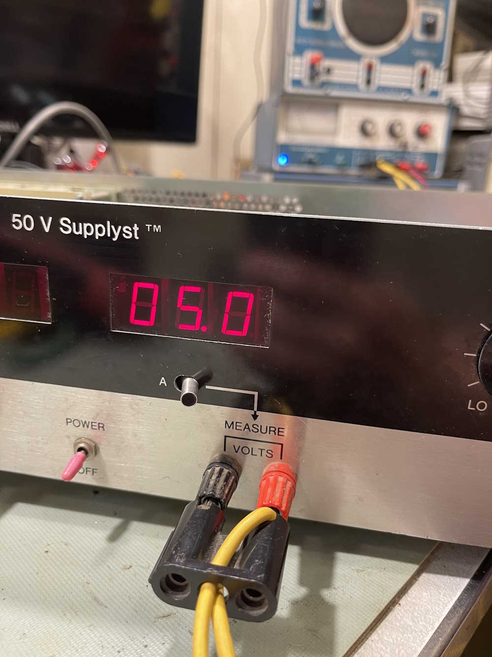
Before I put the new part in, however, I wanted to check the A/D and driver. So…out comes the trusty old Heath/Zenith supply, set to 5V.
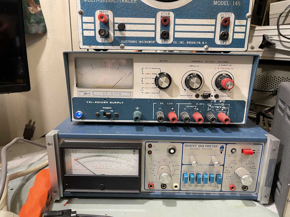
I injected 5V into the regulator output terminal pad, and the display came back without issue. That’s good - those chips are expensive these days, and while I have a spare, I’d rather not use it unless needed.

The new regulator is installed, and main power is applied while monitoring 5V. There’s still an issue, the display is still rolling. Measuring the input reveals the problem, you can’t regulate 5V from 4.5V…

So, what’s wrong here?
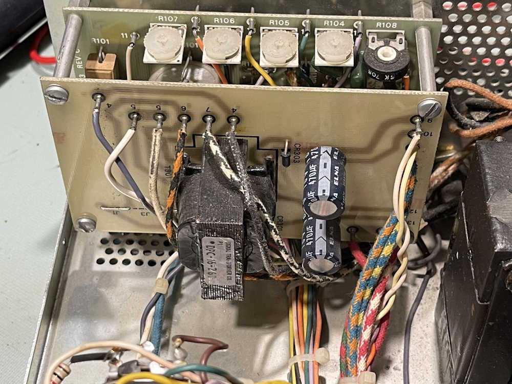
The 5V supply is provided by an unregulated supply that floats at about 9V under load. It’s a simple affair, a transformer, diode, and a capacitor for each side. This provides isolation from the main supply and doesn’t bleed off your supply current to run the device itself.
There’s only really three things that could be wrong:
1: The transformer is bad.
2: The diode is bad.
3: The capacitor is bad.
Chances are…it’s number 3. I’d guess if I scoped this, I’d find that the output of the supply is nothing but ripple because the filter is dried out. I need to get some 470μF parts of known quality to replace the ones in here in order to check, as all I have in stock is what I purchased at Radio Shack from one of their parts kits - back in the 90s…
In the meantime, I disconnected the unregulated input, and applied 10VDC to the input of the regulator.
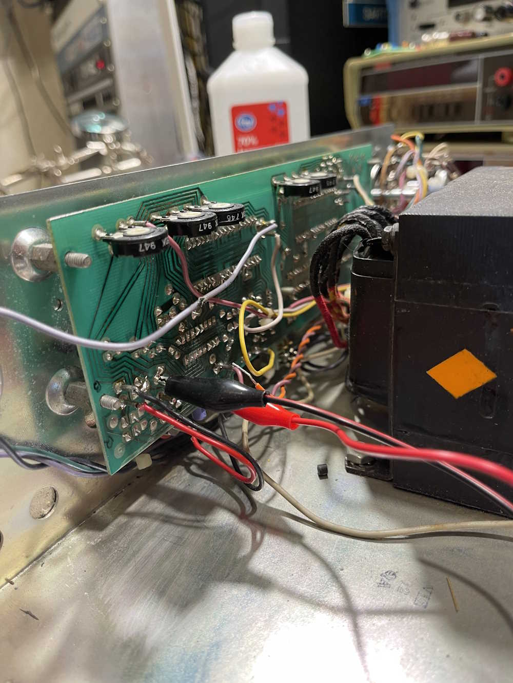
And the device came right up, and I was able to use it’s input to measure 5V from the external supply. It’s quite a ways off (this should be closer to 5.8VDC) so there’s going to be some tweaking needed once we’re all back in operational order.
Stay tuned for part 4 where the capacitors in the supply’s supply get replaced.
Next part of this series: https://wereboar.com … art-4-the-fix-is-in/
Previous part of this series: https://wereboar.com … 2-musings-on-faults/
Wrapup and link to all posts: https://wereboar.com … -and-final-thoughts/