The Superior Instruments Co. Model 76 Bridge part 1: Observations and excuse me what?
Friday, February 6, 2026 at 07:47:51
A month or so ago, I made a post about this device, the Superior Instruments Co Model 76 Bridge and Signal Tracer. The unit combines a single tube headphone amplifier for tracing with a bare-bones CR bridge for capacitor testing. You can find that post here: https://wereboar.com … cent-acquisitions-1/ if you’d like to read it.
There’s a lot going on inside of this device. Much of what’s going on inside of this device is of the “What?” variety as the schematic and device itself do not match very well, if at all. The basic components are there, but the actual values and some of what’s there isn’t.
Here’s the device schematic, courtesy of the BAMA archive:
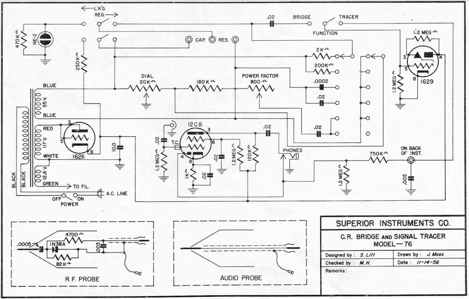
That manual and schematic is located here: https://bama.edebris … manuals/superior/76/
Here’s the bottom of the chassis:
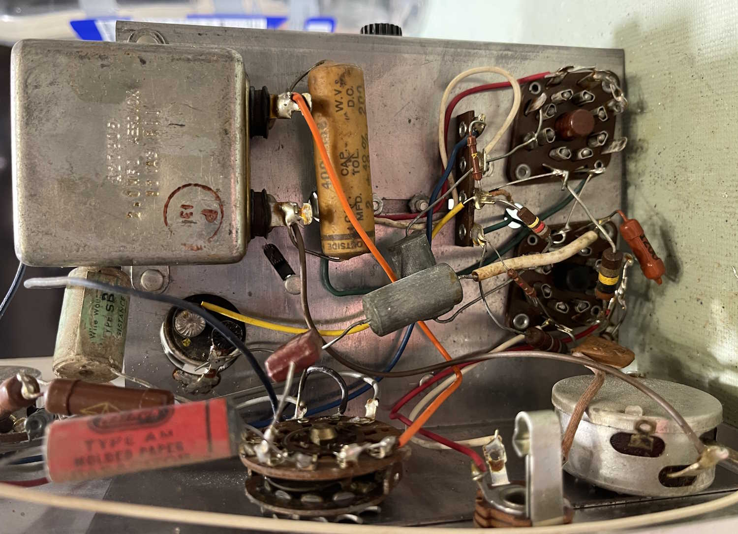
That big motor starter capacitor with the 0.2μF wax-paper across it? On the schematic but listed as 0.02μF . Those two metal cans with no labels in the middle? Not on the schematic…what even are they? They look like capacitors but one measured nothing, the other measured 17μF with a capacitor analyzer. I don’t know that this was available as a kit, so either the OEM just stuck stuff in as needed to solve problems, or someone added these later. I’d go for the “added later” due to the multiple types of sleeving and the fact I’ve seen another one of these that didn’t have those parts.
But there are other things going on in here.
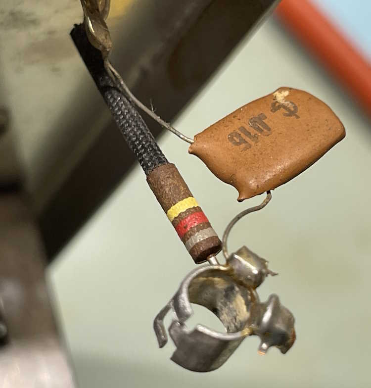
Those are the parts connecting the grid input of the VT153/12C8 tube to the input jack. The schematic states those two parts should be 0.02μF and 1.2MΩ, but instead they are 0.015μF and 820kΩ. Many of the 0.02μF parts in this device are actually 0.015μF ceramics.
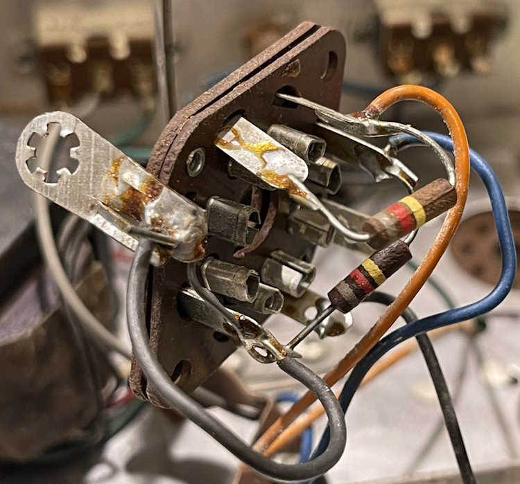
Here’s the eye tube socket. Those resistors are also supposed to be 1.2MΩ but instead are 820kΩ. Like the capacitors in the previous image, many of the 1.2MΩ resistors specified are actually 820kΩ.
It’s obvious this device was built from surplus WWII components. The USN tubes, the RNx resistors, and the oddball parts are all surplus, so it’s no surprise that things don’t match here. However - it’s going to take some doing to rework this item as I can’t simply order things based on the schematic.
The device is working, so there is that. I’m going to work with it a little and try to produce a corrected schematic before proceeding. Stay tuned!
Next part of this series: https://wereboar.com … actually-in-the-box/