A Simpson 715 AC VTVM Part 7: Let’s get that rectifier replaced.
Tuesday, March 31, 2026 at 12:14:19
The selenium rectifier in the Simpson 715 isn’t going to replace itself, even though I wish it would. Therefore, it’s time to start the task of doing that. I started by making some assumptions about the current flows in each of the B+ sides…which were wrong. I knew that ~2mA flowed in the B-side of the power supply, but I had no idea what the A-side would be. This really didn’t make sense to me as there’s supposed to be 10V dropped across the B-side resistor, and 2mA would not do that with a 10k resistor - you’d need 20V dropped. Regardless, I left the 10K resistor in the B-side circuit for the first part of testing.

I originally started with my assumed parts, and quickly set those aside. I then went for a 1k resistor with a 200Ω pot, but found out that wasn’t enough. A 5k pot was chosen, and I was able to dial in the necessary 130VDC. I did the same thing with B-side, and after adjusting both pots I was able to come up with values.
After testing, I settled on 1.27k for the dropping resistor (selenium replacement) feeding the A-side, and 5.168k for the dropping resistor feeding the B-side. With that, I now know that (approximately):
Input voltage = 123VAC
Rectifier output = 173Vp, or (Vin*1.414)-Vd
If we want 130V on the A-Side B+, we need a drop of 33V across the resistor being used to simulate the selenium device. That means in 1.27k, abot 26mA is flowing:
I=(Vdrop/Rdrop) or .0259A=33V/1270Ω.
10 volts needs to be dropped by the B-side dropping resistor, so that means in 5.168k, about 2mA is flowing:
I=Vdrop2/Rdrop2) or 0.0019A=10V/5168Ω.
So we now know that the A side is requesting ~24mA and the B side is requesting about 2mA, for a total current flow of about 26mA. Note that I’m using approximat values because these will fluctuate slightly with line voltage and with the tubes themselves actually doing something.
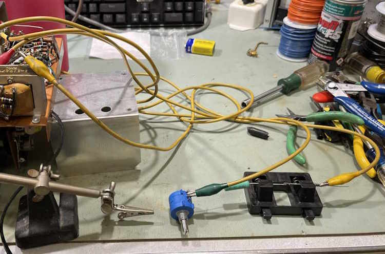
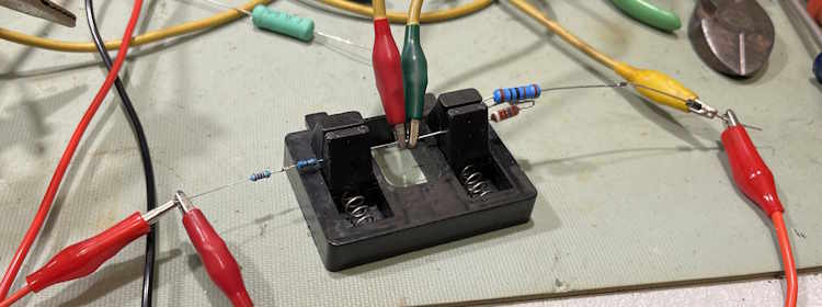
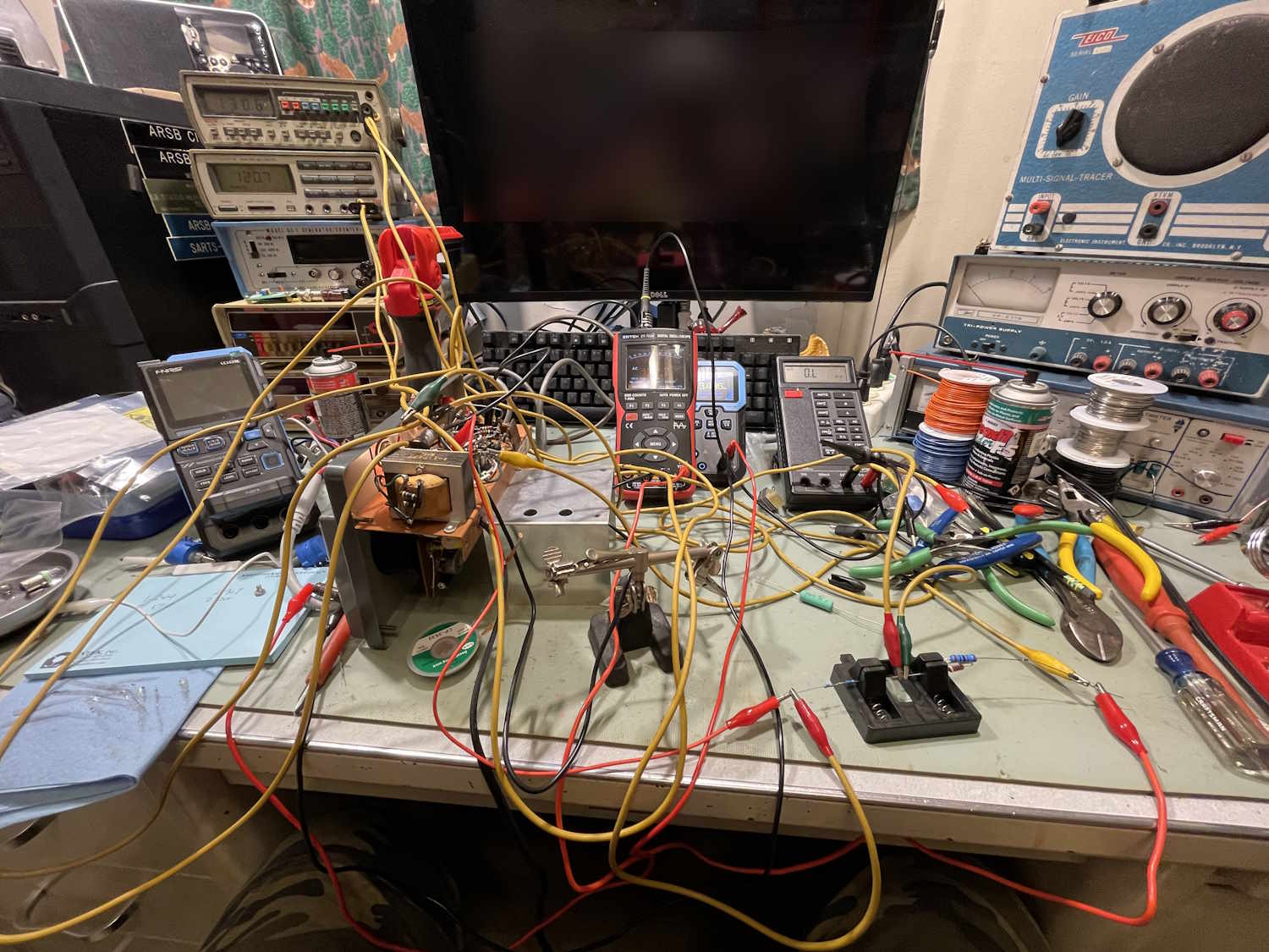
The actual values were slightly different, 1270 and 5170, but I used what I had - a 5100 and a 68 got me close enough, and I had a 1k and 270Ω in stock. The testing of these parts resulted in some organized chaos…
For the diode, I chose a 1N4007, for the specific reason that’s what I have a lot of in my parts stock. Mounting required removing the old selenium rectifier which was just screwed down:

And building it’s replacement on a terminal strip. That j-hook didn’t turn out quite as nice as I’d liked, but it’s solid.
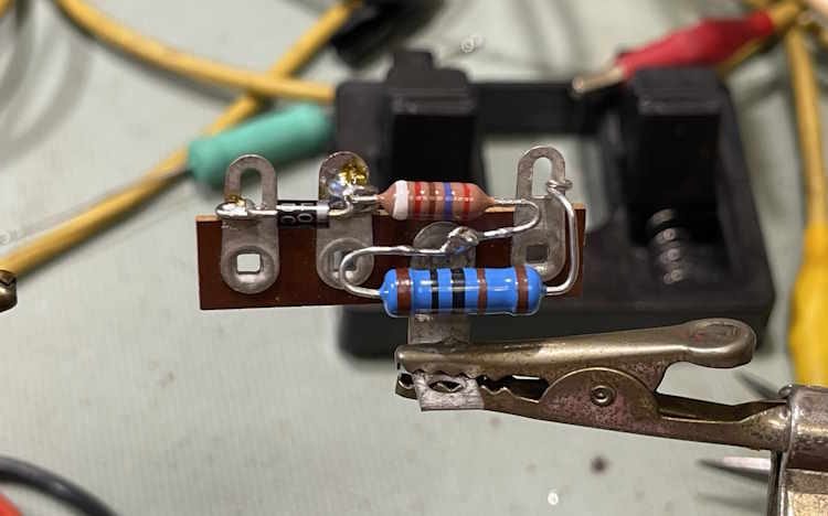
For the B-side B+, I used two smaller resistors since the power was negligible. They routed around the pilot lamp, but I would have liked to have higher power parts for this. Perhaps we’ll look into that later.
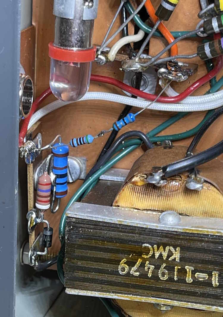
(Note the LED bulb in the pilot lamp socket. We’ll talk about that in a minute.)
B+ came right into the slots allotted for it.
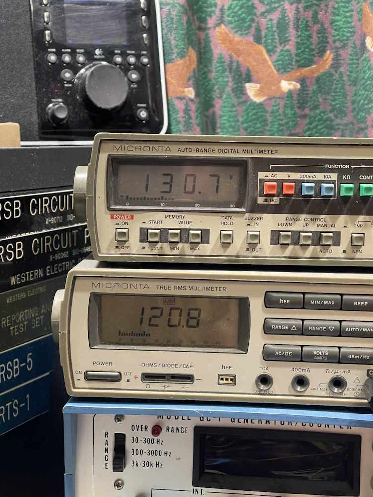
Just on a whim, I tried a LED bulb instead of the #47 pilot. The circuit actually relies on the load from this part:

So it got replaced. A quick check, and on to the final checks…
Next part of this series: https://wereboar.com … part-8-final-checks/
Previous part of this series: https://wereboar.com … part-6-intermission/
Wrapup and final thoughts: Coming soon.