Almost all of the parts in the TE-189 C-R analyzer are available, save for the switches and the panel lamp. While the switches would essentially put the unit in the parts bin, other things like the panel lamp can be replaced with something else. It’s just a neon bulb in a package.
The one on my device was long since dead, so I tried to peel the case apart and replace the oddball neon bulb inside with something else. The case plastic was old and crumbly and that went about as well as you’d expect. It didn’t. On the off chance there was something similar out there, I did some searches and ran across the exact part on an auction site. And when I say “exact,” it’s OEM…
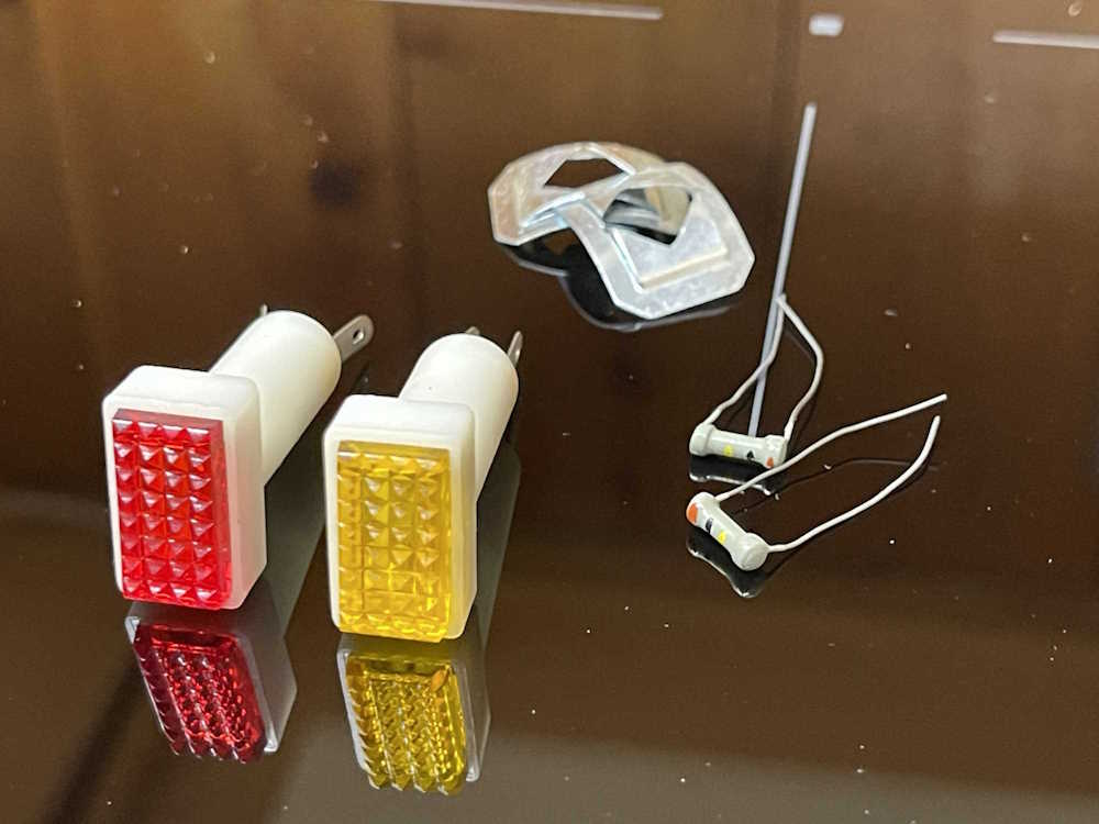
This is a pair of Herald Electronics miniature neon panel lamps. Herald Electronics of Chicago, originally called American Electronic Parts, was a sub-brand of Olson, and as such, one of their suppliers. Olson didn’t publish the fact that they owned this other brand, so Herald was apparently able to sell parts and supplies to other vendors for resale, without incurring the “We don’t want to buy from a competitor” thing you’d get by buying from your competition.
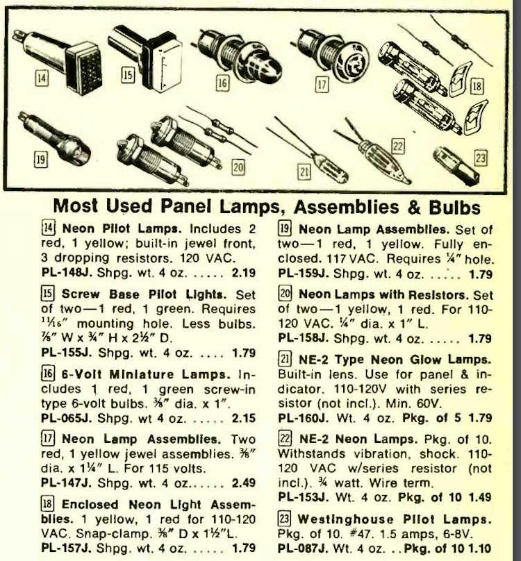
Herald, of course, sourced their product from various Japanese manufacturers, and vanished when Olson did. It was quite the surprise to find these parts, still new. I bought them right away. Here it is in the 1974 Olson Catalog:
There were 3 pieces for $2.19. Figure 14, part number PL-148J. Someone bought a set, used one, and put the rest in a drawer. Fortunate for me!
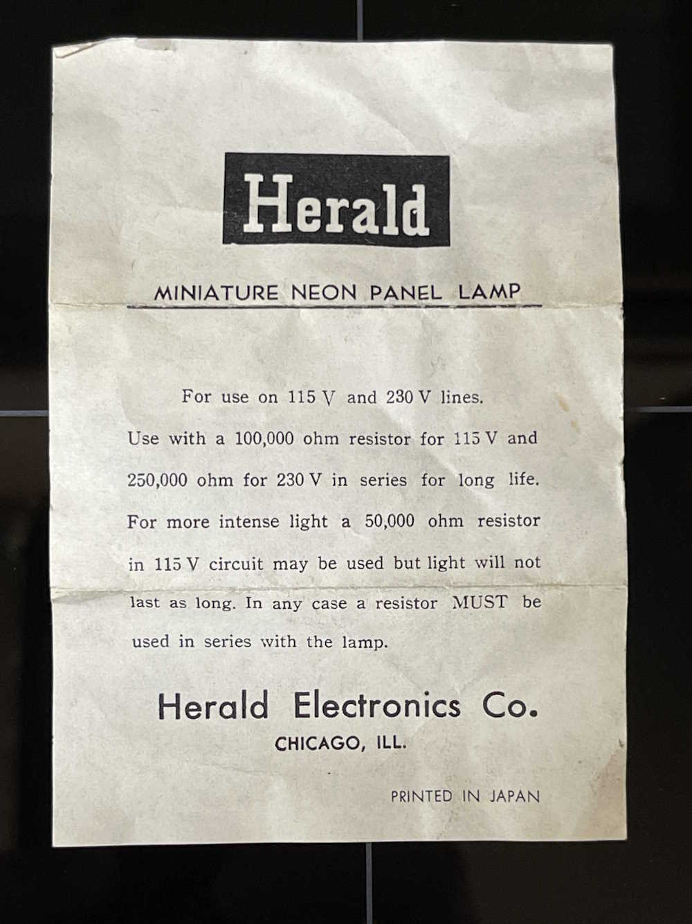
It came with the original pack-in paper pamphlet:
Interesting that the paper specifies a 100k resistor for longer life. The TE-189 has a 50k, so that probably didn’t help the lamp life. I replaced it with a 100k as specified.
The parts themselves are exactly what I needed, down to the little alignment tabs on the bottom. No surprise, they are the exact OEM part. I love the little dogbones they gave with the lamps.
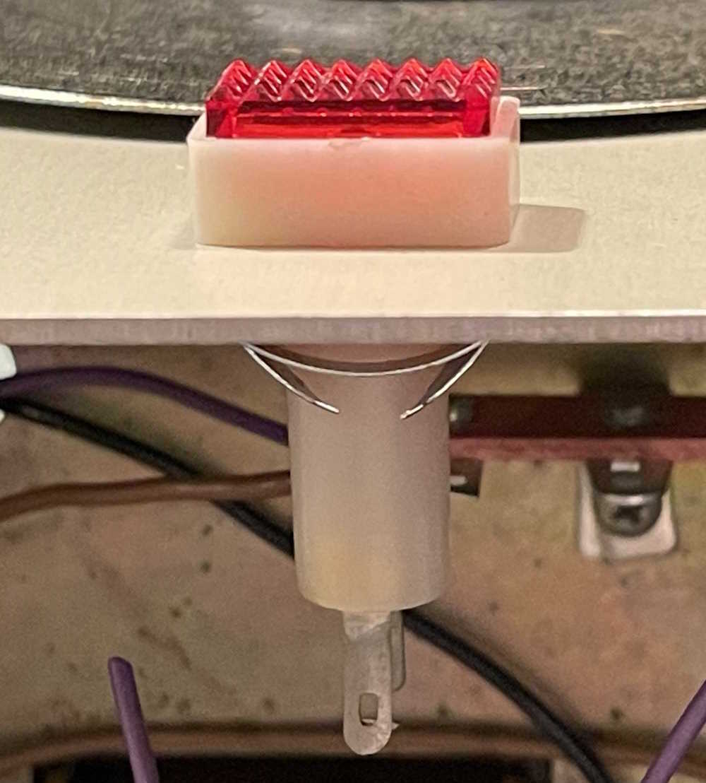
And, of course, it fits in like it was made to be there. Here it is, waiting for wiring in to the panel.
I’m waiting for some wire and a new 500Ω power resistor. The mail is not cooperating right now, so stay tuned!
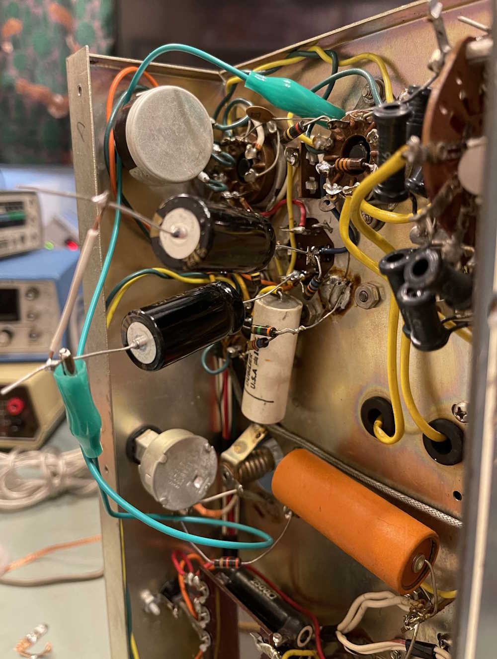
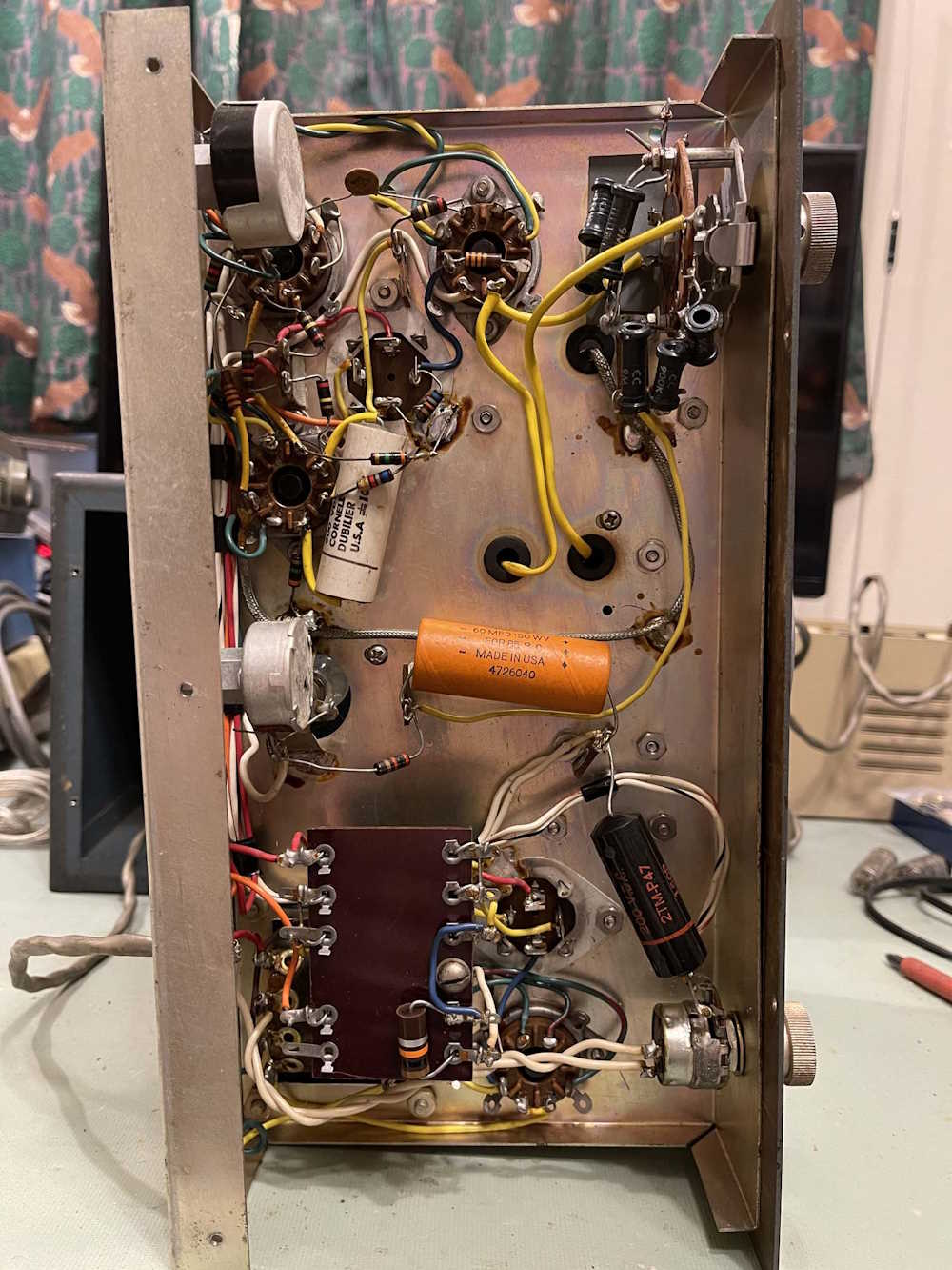
SO…I thought that the TE-189 job would just be some tidy up and new capacitors. No, that’s not going to work. Turns out that the builder of this device (I hope this was a kit!) managed to get about 50% of the solder joints to hold. The rest were nothing more than burnt wire and insulation, badly wetted connections, and connections that were just kind of wrapped around one another and soldered with prayer.
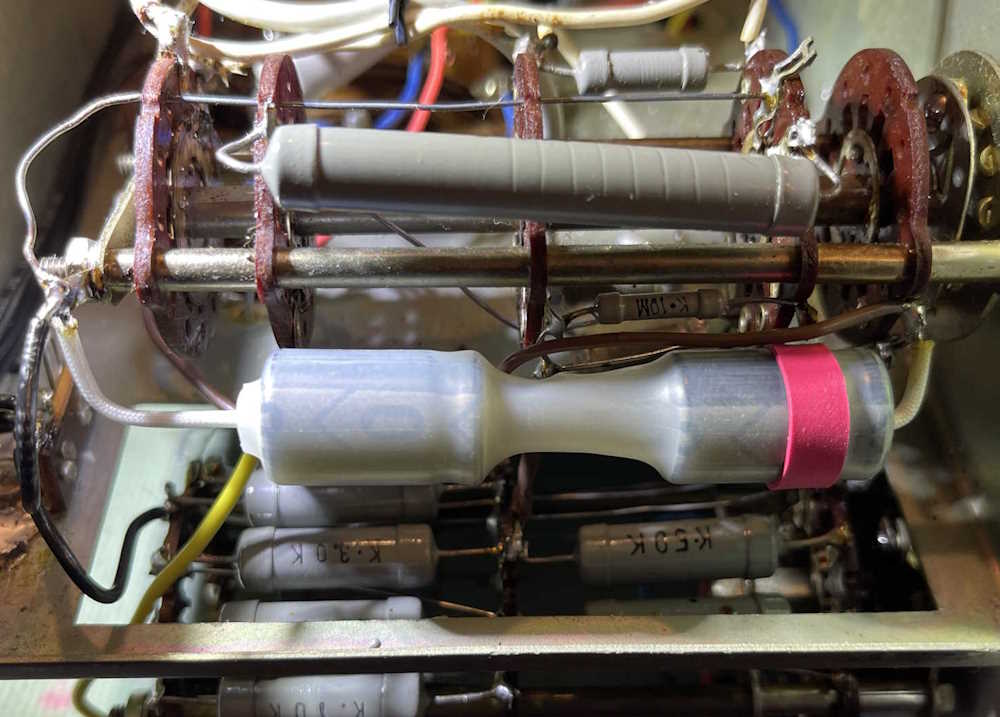
I spent some time last night installing the new filter capacitor. Since a 5μF @ 700VDC is kind of hard to get at a reasonable price, I chose to use two 10μF @ 450VDC instead. These were connected in series to give the requisite capacity at 900VDC. I wrapped them in heatshrink and gave it a red band to identify the positive side of the device. That’s when I started to notice how badly the thing was wired.
You can see a brown wire attached to the same terminal as the positive side of the filter. This wire was just kind of stuck in the solder and came right off when I hit it with the iron. There was enough left that I could cut and strip and insert properly.
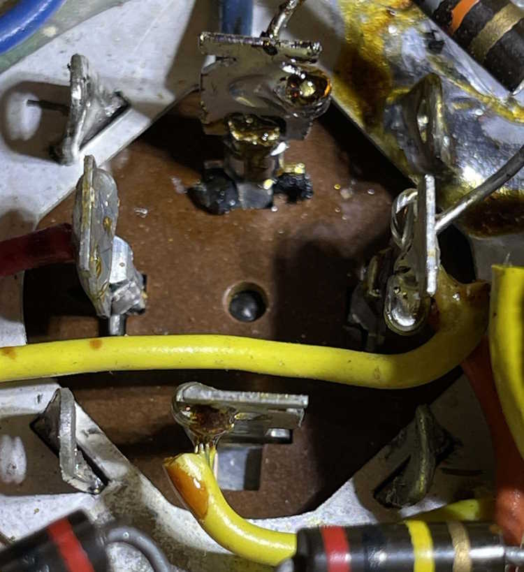
The grounds on this thing are a complete mess. A small terminal on the switch had multiple leads inserted in it - rather, attached to it. One was in it. One was wrapped on it. One just kind of hung there. A big blog of solder attempted to hold it all together. Grounds are flying everywhere in this thing instead of coming back to a single point. Plenty of other wires were the same with some just wrapped around other leads and soldered right into the insulation. Even the original filter was a wrap-job and wasn’t wetted properly.
How did this thing even work? Or did it? The neon bulb was dead so it spent some time on during it’s life…
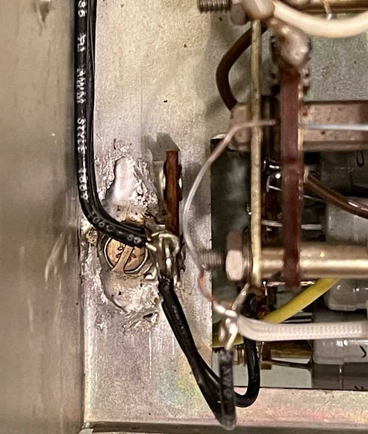
I decided to solder a terminal strip directly to the chassis. Clean and wet the chassis and terminal, and hit it with the 80W iron. I know I’m talking about solder quality, but my 80W device is just not enough for this task. I’ll pick up something bigger this year. It did a (poor looking) job, so all grounds will now come back to this point.
There are around 10-ish ground connections going to all different places in the unit. I’m going to run them back to this double lug so they’re all at the same point. That involves removing a lot of other stuff, including jumpers across the transformer terminals, and a lot of stuff on the other side of the chassis. I’m going to run all of these and then slowly work my way across replacing wires that are in need of replacement. It’s going to be slow going.
Here’s an example of what I’m seeing - this is the ground for the 450-0-450 portion of the power supply. It was just kind of shoved through a terminal on the transformer and hit with some solder that didn’t really wet the lead. The across the line cap was then wrapped around the lead and soldered without removing any insulation - the capacitor just kind of melted into the plastic and didn’t really wet. It all goes away.
There’s a big lump of grounds just to the right of this that I’ll correct, and then start replacing capacitors and fixing the tube socket and the HV power supply.
I’m getting ready to replace some of the parts in this device, and I decided to take a look at what I’m doing and consider things.
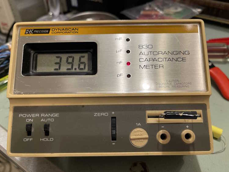
I recently cleaned up an older B&K Capacitor Checker, and (in theory) this device should be a good reference instrument for measuring parts in this device. I decided to check things and it made me wonder if I really should replace all of them. There are some that will most certainly get a new part in their place, but others…
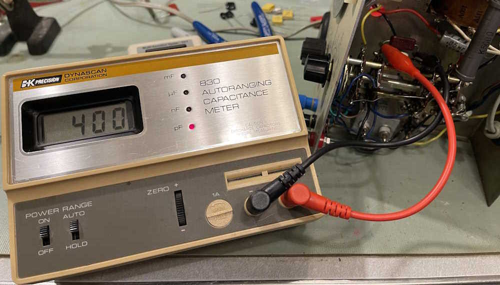
The first is the 400pF mica capacitor. I originally thought this thing was a mod, as it has a capacitor and a trimmer. However, I’ve seen another unit under rebuild and it has the same thing. The trimmer itself is plastic, so there’s no way this thing is approaching 600V, but it adjusted down perfectly and I had a good 400pF on the meter.
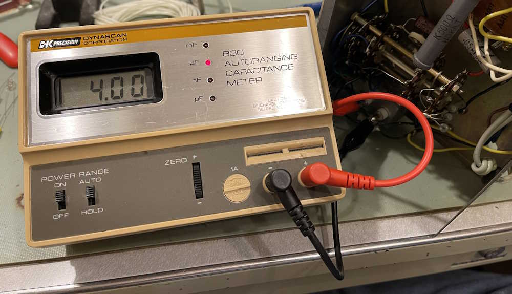
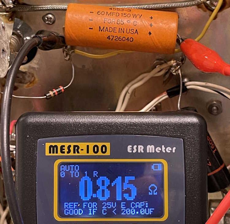
The big 4μF was similarly in good condition with this meter.
This one has good ESR and has a big 1k resistor to absorb the brunt of any voltage, so I think this and the 400pF will just be left alone for now. I have replacements in case they do need to go, but they don’t right now.
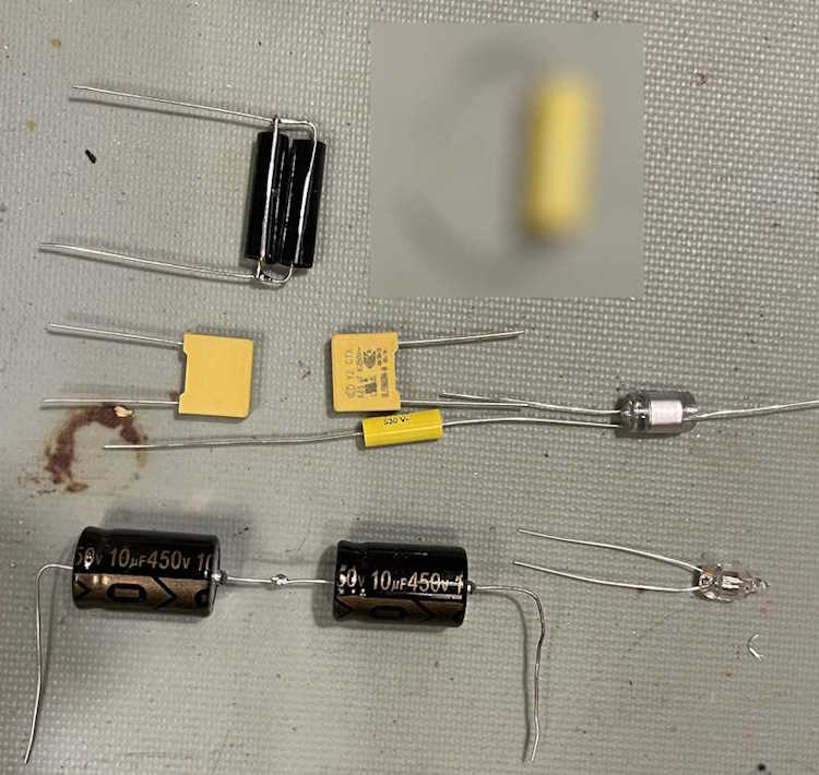
What does need to go is all of these metal can parts, especially the across the line capacitors and the filter. For the 40nF capacitor, I chose some 1% film parts at 630V and paralleled two of them for 40nF:
For the filter, two 10μF in series at 450V to make a 5μF at 900V. This part will probably get some heat shrink to strengthen the assembly. I chose this route because it was much cheaper than trying to find a part rated the appropriate voltage.
There are some resistors as well that seem out of tolerance, but those will need to wait. It’s not like this thing is going to be as accurate as a modern digital meter, but my concern was to prevent electrical problems.
The entire parts set to be replaced (save the 4μF):
1x 5μF filter capacitor assembly, electrolytic.
1x 40nF test capacitor assembly, film.
1x 0.01μF input blocking capacitor, film.
1x 1500pF capacitor for the eye, polystyrene.
2x 0.047μF across the line capacitors, safety film.
1x A1C neon bulb for the front panel.
Also, I am going to replace a poorly placed 1MΩ resistor across the eye tube, and perhaps the 1K and 500Ω resistors used in the test circuit (with the 500Ω just kind of hanging there in the air.) The latter two are both high-wattage parts (of unknown power) so a 10W part should be more than plenty on these.
That’s it for now - the next step is to put the parts in. That shouldn’t take long, but I’m also going to clean up some of the wiring as it’s in terrible shape. Stay tuned!
In the last part, I determined that the tubes (save perhaps the 6×5) were not at fault in causing this device to act up. After I wrote that post, I sat down with it just a bit more and did some poking.
First thing was to put a good 10k power resistor in place of the one that rose to 160k when warm. No change in operation. Second was to give it a good look-over one more time.
I noticed that there was some goo coming out of the electrolytic in the oscillator section. That’s not good.
Ok, so that capacitor is probably bad. I measured the DC voltage on it.
There’s a really slow variation in the DC that matches the oscillator’s on-off cycle. I did some quick bypass with new caps, paralleling the presumed bad devices:
No change.
This thing has more problems than I originally assumed, and the lack of any information on the unit is hampering my ability to work with it.
For the time being, this goes back on the “needs work” shelf, as I already have a working generator and need to get some other devices fixed. If I can get to it before Hamvention, then I’ll take another look. Stay tuned!
Every resistor in this thing was bad. Without a schematic, it’s just another piece of ancient technology, and I already have plenty of audio generators. I let this one go.
The Scott Antique Market happened this weekend, and much to our (and a lot of other people’s surprise!) it opened an hour later at 9AM. Remember what I said about checking hours? Well…guess what this stupid little pig didn’t do?
(Some update notes on this - it could be a regen unit as well, according to some. The little glass part marked “GLASTOR” may be a grid-leak resistor, aka GLASs resisTOR. And, there are no parts under the wooden plate. What you see is what you get!)
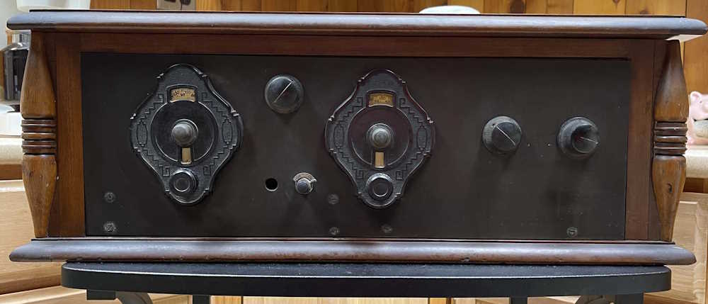
Anyway, there was some good stuff to see, but I didn’t really see anything I wanted to bring home until we were getting ready to head out. My show-going companion stopped by a big coffin set on a table. The guy had a price on it and I was going “That’s a good price for that piece.” I ended up buying a box of tubes he had beside it, but my buddy was stuck on the radio set itself. I looked, hmmm’d…do I have room for this thing. The guy said “If you want this, how about this other, lower price.” Buddy was just looking at me with puppy dog eyes saying get this dude. So I did.
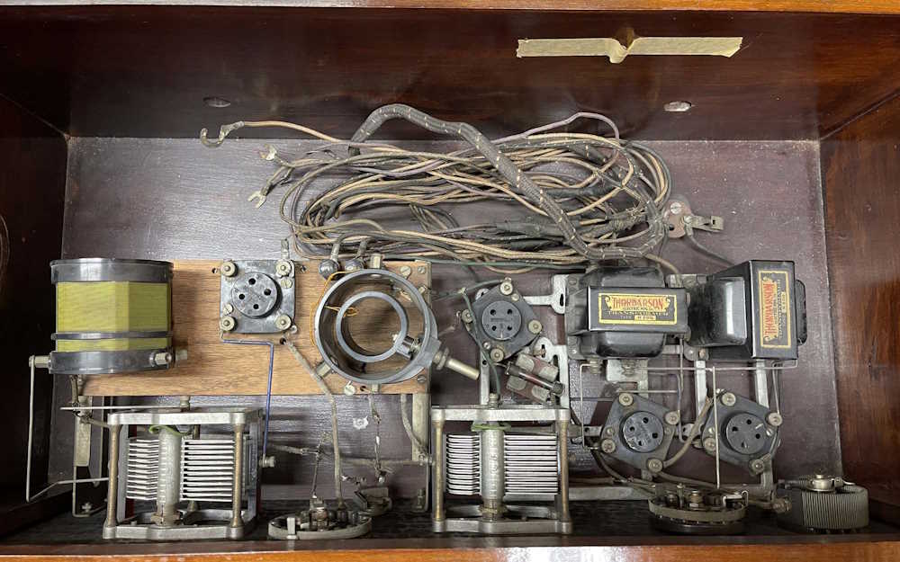
It’s obviously a homebrew set. The empty hole doesn’t look like anything was ever in it. The parts inside look like it was a partial kit, or at least contains parts that allowed you to make your own layout.
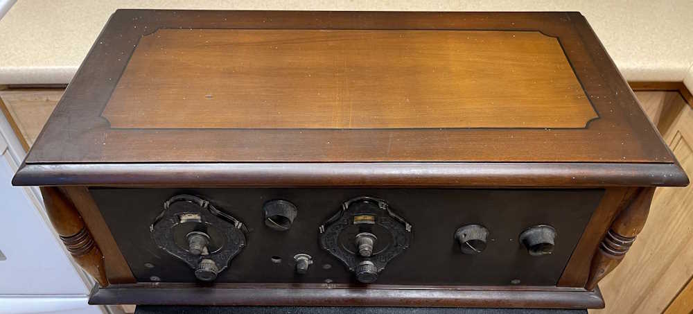
Two tuning capacitors, a couple of rheostats, and an on-off switch adorn the front.
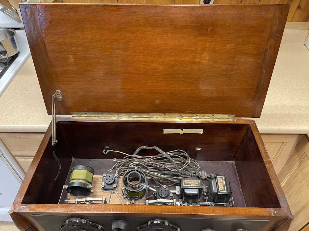
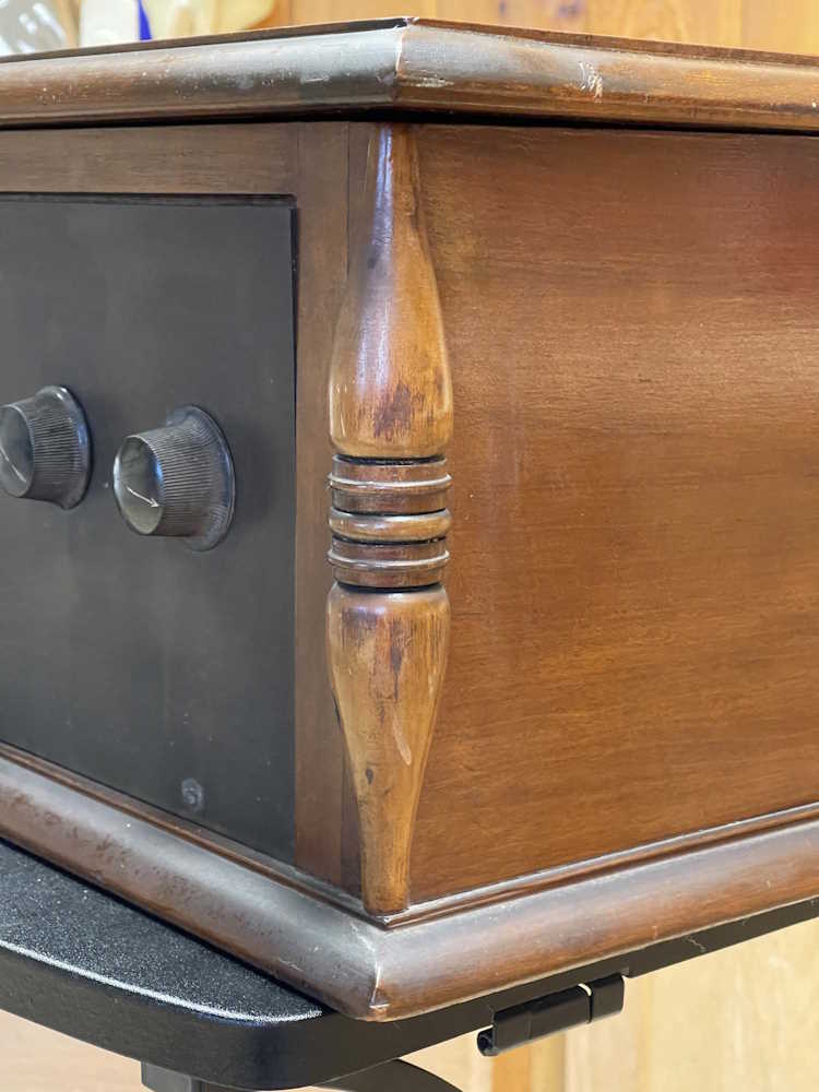
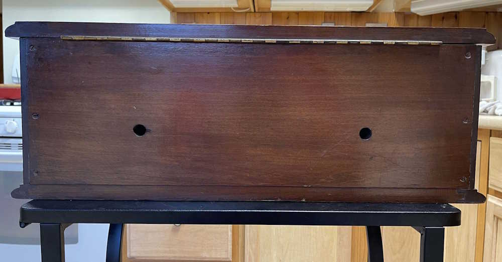
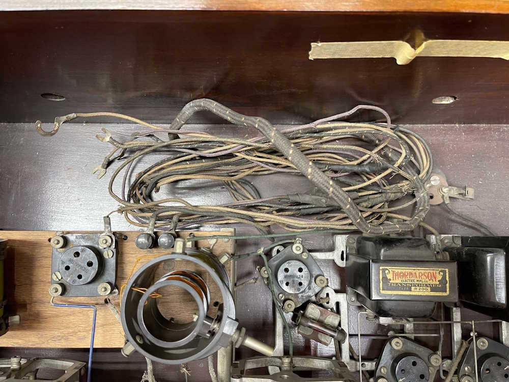
The cabinet itself is pretty good outside. A little scuff here and there and some paint splatter - but considering this thing is probably nearing 100 years old, it’s a solid external 7/10. Inside is very clean, and probably resembles the day it was built. There’s some cloth loss on the wiring, of course, but that’s acceptable and understandable. Some things will need to be tightened up - the escutcheon dials are loose - but nothing major.
Similarly, the rest of the case is in good condition. The varnish on the top is really the only bad spot on the unit.
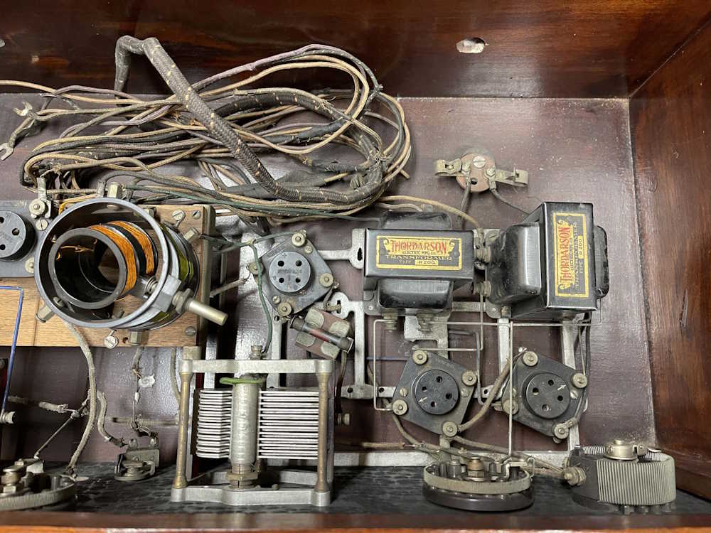
As for the inside…it’s your standard TRF layout. Two tuning capacitors and a tuned inductor present themselves immediately. I’m not really that familiar with TRF sets, so I’m not going to go any further with that in trying to define what they all do. Four tubes, and two interstage Thordarson R200 transformers are really all that’s in this thing. I’m assuming there are some parts underneath the wood plate, but I have not dug that far into the unit.
I’m going to assume this needs +90, +22.5, +5, and +1.5, and that they went in the spot where the cables currently reside.
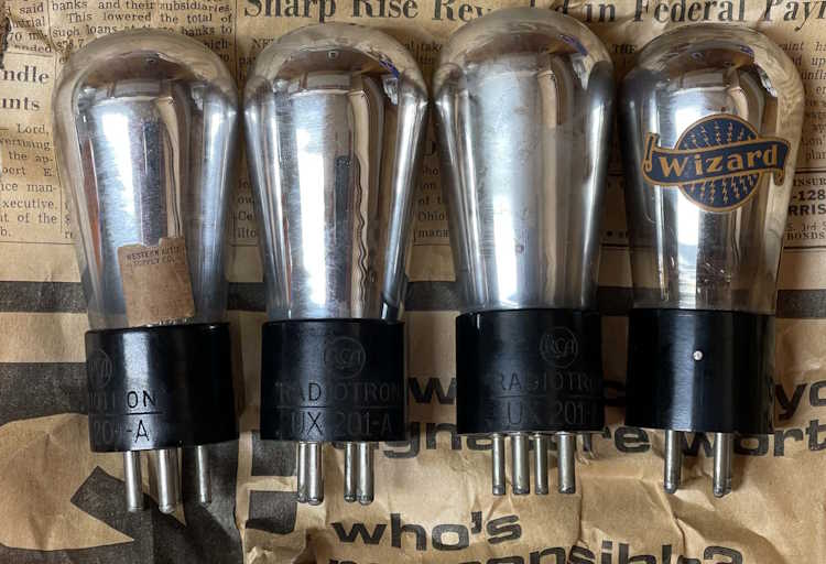
As for the tubes, all of them were present but wrapped in paper, so I don’t know where they go.
Tube compliment for this is 3x UX201A and 1UX200A. The 201’s are all RCA branded, and one has a Western Auto Supply price tag of $5.00 on it - that’s nearly $91 today! The final UX200A is unbranded on the base, but has a “Wizard” sticker on it. It’s also priced at $5.00 at Western Auto - so there’s nearly $400 in tubes in this thing!
The 200A dates this to at least 1926 and no earlier, as that device was introduced in May 1926. It’s possible the unit is older, but I can’t see someone discarding such an expensive tube just because a slightly better model was announced (although it’s possible.) Since superheterodyne was already a thing at the time, it’s probably not much newer than ‘26 as TRF was a rather poor (although easy) way of getting audio from the air.
The paper the tubes was wrapped in is a Columbus (Ohio) Dispatch from 1970, so the previous owner set it aside some 40 years after it was turned on. The paper itself is quite interesting - a story about how banks are cutting back on loans, a story about how federal payrolls are ballooning, and an ad for credit card fraud monitoring and restoration. You could almost change the date and reprint this thing!
Regardless, this was a great deal and I’m happy I brought it home. As stated earlier, TRF is really outside my knowledge range, so my next step is to grab a few early radio books that have TRF circuits in them. It’s quite likely that the original builder followed a schematic in a book or magazine, so finding something similar probably won’t be too difficult.
If you recognize the layout please let me know on Mastodon or LinkedIn, and stay tuned!
As seen in the last part of this series, there’s definitely a problem in this unit preventing it from oscillating properly. It’s time to start digging in and seeing what’s what.
I picked up a new / tested good used set of tubes at the recent Fort Wayne Hamfest. I started with a baseline measurement to make sure everything was acting as before, and then started with the rectifier. The signal output was a big stronger, so the 6X5 is probably weak. Not a big deal, and probably expected.
Going around the rest, including the PTC resistor lightbulb, nothing changed save the signal was again a little stronger with a new 6SJ7 oscillator tube. Not enough to worry about, so all tubes were swapped back to the originals. The problem is in the components.
The device is mostly disc capacitors, and while they do go bad, it’s not often. Ignoring those for now, I decided to do a quick check to spot any obvious failures before powering and measuring voltages. First thing I checked was the big 10k 2W that I assume is a power supply divider.
160k and dropping. Odd…no capacitors here, and it finally settled down to 9.91k. That’s probably the smoking gun right there - the resistor is changing value as it gets hot and driving B+ down to a level where the unit can’t oscillate. Once the oscillator is off and the current is lower, the B+ increases just enough to oscillate - rinse and repeat. I need to check B+ to make sure, but this sure is suspicious.
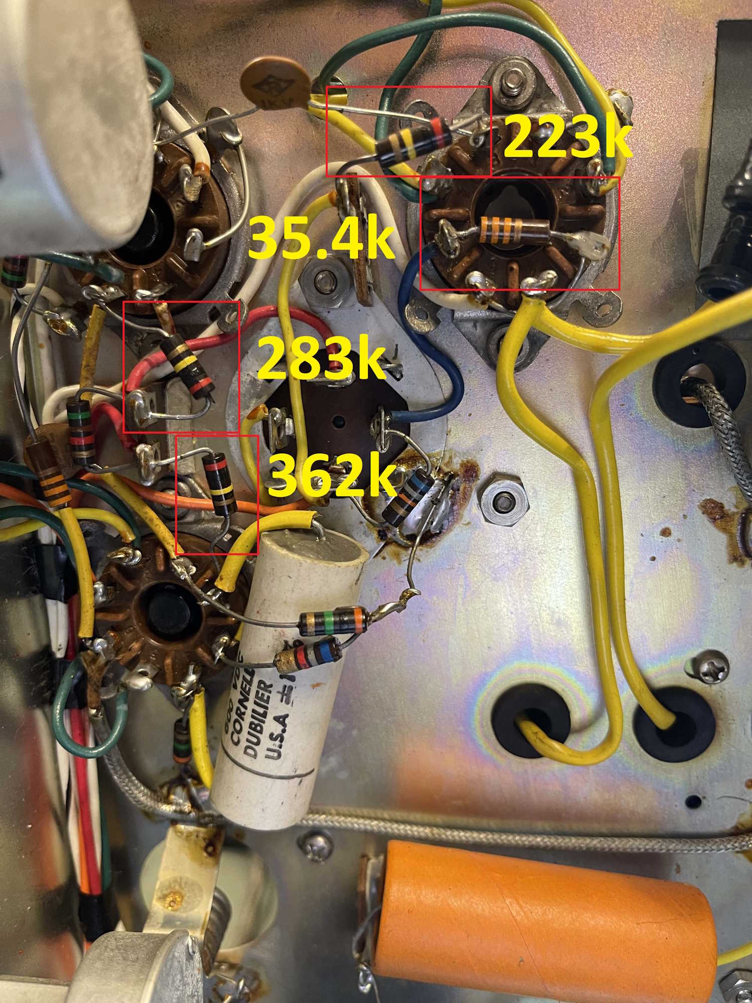
With a reasonable guess secured, I did some spot checks around the oscillator. There’s a 33k across the 6SJ7 that has increased to 35.4k - a little out of tolerance but eh…there’s also a 200k flying off the tube, and it was quite high at 223k. Ok, that’s possibly a problem. I noticed two more of this type and checked those - way way out of tolerance. Everything else seemed to be close enough that I wasn’t concerned,
I wonder what made just those particular ones that bad?
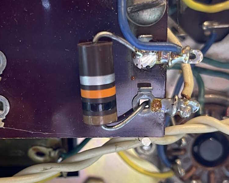
There’s a couple of other things here that probably should go. That big white CDE El-Menco ripoff capacitor is a type that can be problematic. There’s also a dry electrolytic that’s checking fine but probably can go, and a black plastic capacitor that connects to the output control that needs to be replaced because they crack and gain moisture.
There are multiple supply electrolytics, and they all seem to be good. I’ll need to let the unit run a bit and see if they get warm, but if not then I’m not going to worry about them until something happens. I’m going to replace that nasty power cord as well, but that’s just a “always do it” thing for me.
With possible fixes identified, it’s time to set this unit aside until parts arrive. Stay tuned!
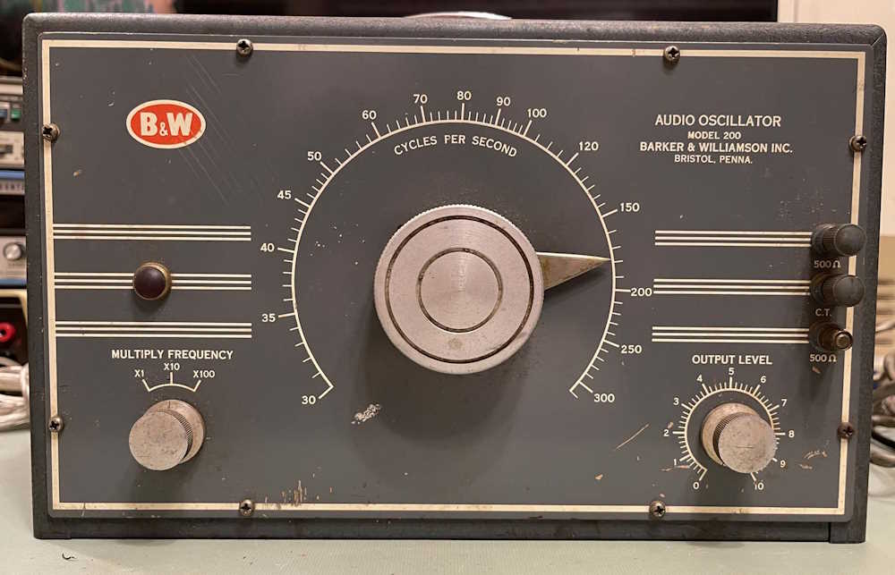
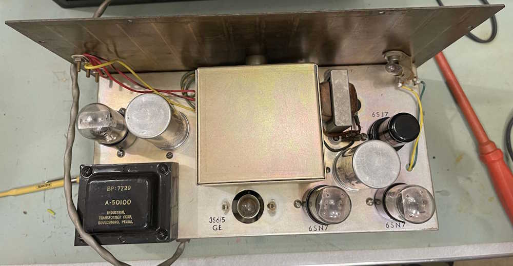
This is a device I picked up at the Dayton Hamvention earlier this year (2024.) It wasn’t much, but what caught my eye is that the thing is built like a brick shithouse. The big dial on the front is just wonderful in it’s smooth spinning. It’s missing a single output terminal cover, but that’s not a big deal.
This looks to be similar to most generators of the era, with a couple of extra tubes. I’m going to assume that since this has a balanced output, it’s using a phase inverter and final amp to drive the transformer output. Otherwise, it’s your standard oscillator and that old GE lamp as a PTC resistor, just like you’d find in a Heathkit or other type.
Tube compliment is:
6X5 as the rectifier
6SN7 as the final drive amp
6SN7 as a phase inverter
6SJ7 as the oscillator
GE3S6/5 lamp as a PTC resistor in the oscillator
(I assume)
The bottom is fairly clean. Some capacitors probably need to be replaced…
But a quick check says maybe no?
Output looks ok…
But about 3-4 minutes later the signal starts falling off, as in just fading to zero - and them coming back up. It just keeps doing this over and over, no matter what the output level or frequency is. I’m not sure what’s going on here, but the signal comes back up like the oscillator tube is dying.
I’m not sure what’s going on here, so I’ve picked up a new 6SJ7 and a couple of checked good 6SN7 to sub out and see if it’s one of the those. I have a used lamp laying around somewhere and I’ll check that as well. Other than that, I haven’t really investigated things much as data about this unit seems to be kind of scarce.
The device is working properly and has been buttoned up and put in it’s home on the bench. Here are my thoughts on how things went…
Thoughts
This unit was really the opposite of everything you expect from an old device. All of the passive components inside, like resistors and capacitors, were in good shape and don’t need replacing yet - although at some point it probably will require electrolytics. That’s for future me to decide.
This device really shows that you have to expect anything with an older device. Parts that don’t do anything other than hold a part can degrade and cause issues, especially when working with the higher voltages present in a vacuum tube device. I never would have though that a tube socket would fail like it did. Sure, they fail because the sockets themselves get weak, corroded, oxidized, etc. and make bad contact, but arcing across? That’s new to me.
I supposed it shouldn’t be unexpected, carbon tracking is a thing. The moral of this story is expect the unexpected. Especially when working with an 60 year old device that was built from a kit.
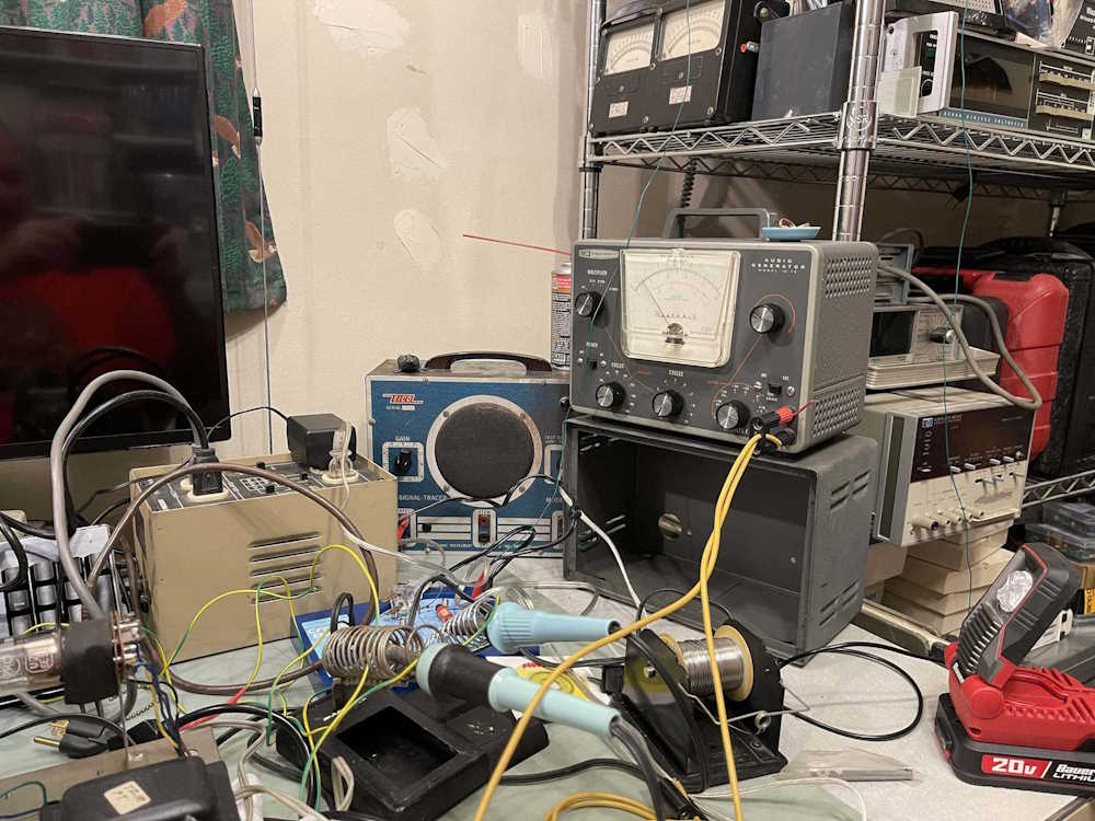
The calibration - more of set up - for this device in the manual was written for a time when you probably didn’t have a Hi-Z meter on your bench, but pretty much everything is these days. Instead of following the manual, I did this:
Equipment required:
Oscilloscope
Voltmeter that’s accurate at 1kHz
Leads and stuff
1: Set the frequency to 1kHz, attenuator switch to maximum, and set the output level to ~5VAC RMS using your meter. Ignore the meter on the face of the unit for now. Connect your scope and meter to monitor the output.
2: Let the device warm up. Get it nice and warm. I put a cardboard box over mine to get it toasty. I think this is also how I got it to arc continually so be careful here - don’t set it and forget it. Heat is going to cause marginal things to fail. Check on the device every once in a while during warm-up.
3: After a few hours, when the device is warm, check the sine wave output on your scope. Slowly adjust the oscillator output control (the potentiometer on the inside of the chassis closest to the transformer.) Adjust the sine wave until you just start to get one of the tips cut off, and then back off a decent amount so you have a good sine. Note: These have decent high output with fresh tubes, you can probably back off a lot here. And, I do mean a lot - this will drift so give yourself plenty of headroom.
4: Let it set for a while. You may need to adjust this sine wave a couple of times.
5: When you’re happy with the sine wave, adjust the output level to 5.00VAC RMS with your meter. Using the meter level control on the chassis (it’s the other potentiometer inside the unit,) slowly adjust until the device’s meter so that it agrees with your meter. I use 5V because it’s dead center of the meter’s scale.
You should be able to assemble the device at this point and have a clean sine with a reasonably accurate meter. Note, however that this meter isn’t calibrated at every scale and frequency, so it’s a best guess at all times. The manual even warns about this, so if you need a precise level always let the unit warm up and adjust with an external device connected.
After everything was said and done, I had an accuracy of about 2% with the selected frequency. I think that’s pretty good for a device from the late 50s.
Why did I choose 1kHz? Primarily because this is going to be used for signal tracing. You can choose whatever frequency you think is best for your purposes.
One of the things I’m considering is trying calibration at 10VRMS. That is, set the level control to the maximum, and then back the oscillator control off until there’s 10VAC on the external meter, then adjust the internal meter to follow. This should keep the system well within the linear range. That should be possible since the output is constant before it appears on the attenuator’s input - but there’s always the chance that it won’t oscillate at some point (frequency) because it’s lower than what the circuit is expecting. It’s going to require experimentation to see.
That’s all with this device. It’s been on quite a bit as I’ve used it for testing devices that are in the “keep or sell” pile. If anything else happens to this, I’ll post about it here on wereboar.
(It’s actually a TE-189 device…how did I miss that. Really wearing my stupid hat on this one!)
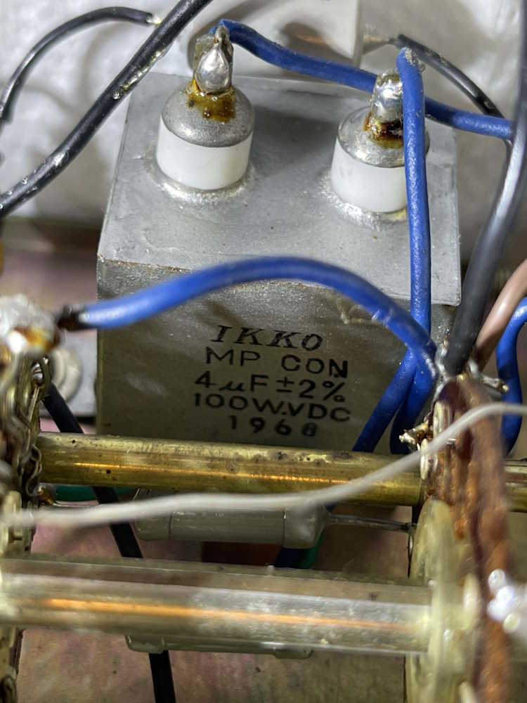
One of the parts in this device that probably needs replaced is a big capacitor in a metal box.
I was looking at this going where have I seen this before, and how do I replace it.
A quick search and yes - it’s a metallized paper capacitor, and was probably used as a motor start capacitor. That style of device is still available, but it’s not common these days - metallized films have taken over the market. The value of 4μF is kind of odd as well, but shows up both in modern motor start caps, as well as capacitors for speaker crossovers. Since both are non-polarized like this one, replacing it will be easier than I expected. 2% parts are a bit harder to find, but available with a little searching.
Some other things I’ve noticed about this unit:
- The threadlocker that was used is very very good. The meter and the dial pointer were both held in with screws that were coated with a white paint-like substance. When I removed the dial pointer screws, they both snapped. These seem to be closest to a 4-40 3/4” Oval Head screw.
- The paint on the knobs on mine was flaking already, and an ultrasonic cleaning removed a lot of the rest.
The point here is to be careful with the old stuff.
(This is a TE-189…oops! I think I’ve corrected all the bad links out there…)
The short answer is everything here that needs to work seems to be working. The long answer is probably all of the capacitors that are in the circuit, the power cord, and the neon pilot (because who doesn’t want the nice neon glow?)
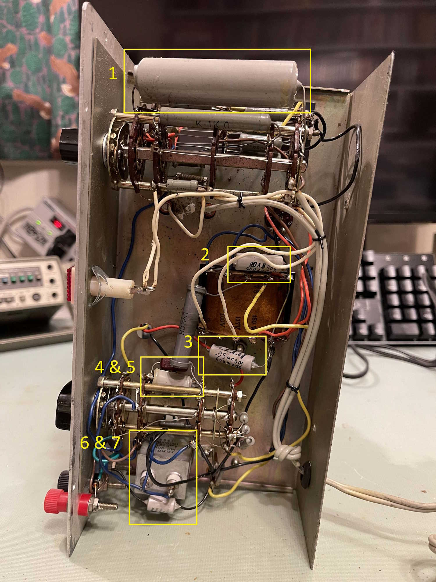
Looking at the unit, there are several capacitors - but not as many as you think - in this thing:
#1 is the big one - this is a 5μF at 700V filter capacitor. Is there really a need for something with this kind of rating in this circuit? You bet:
Almost 600VDC is present on this device, so it’s certainly a good candidate for replacement. The OEM left some overhead there, so it’s not completely shot at this point. I have to wonder how this device ever worked, however - the negative lead on the capacitor wasn’t soldered very well and didn’t wet. It just slid up and down on the ground wire.
It’s not the easiest to get something like this in a modern part, so two 10μF @ 450V in series would make an equivalent replacement of 5μF @ 900V. Fine for this thing.
#2 and #3 are “Across the line” capacitors. One goes across the AC line, the other on the tube filament line. These are 0.05μF at 500V. One of them doesn’t need to be that high, but both could comfortably be replaced with 0.047μF at 630V devices that I keep in stock for that very purpose.
#4 and #5 are part of the measurement circuit. 4 is a mica of unknown value, and is the deep red part tucked behind the dogbone resistor. It’s interesting in that it has a ceramic trimmer (you can’t really see it) in parallel. I cant imagine this was the OEM setup, but perhaps it was. #5 is a simple .04μF capacitor. I can’t see the voltage on this one because it’s so tightly packed into the switch. Since 0.04 isn’t really a modern value, parts chosen from a bag of cheap 0.022 parts could probably make a cap that’s closer in value to the original.
#6 is a DC blocking capacitor. Nothing special here, a 0.01μF at 630V - or just about anything close - will work. It feeds the grid on the eye tube.
#7 is the odd man out. This is a 4μF at 100WVDC - nothing special you’d think, but it’s in a metal case, almost like a motor capacitor. I’m not sure what the significance of this style of part is. Perhaps it’s a low ESR or has special power factor qualities? It is in the power factor test circuit that gets adjusted on the front panel. More research is in order here, but the part reads 3.76μF in circuit. Assuming it’s a 10% part, it’s still in tolerance. The schematic I have doesn’t say, so…who knows. In another rebuild I saw, this one didn’t get replaced. (no, it’s 2%…odd!)
There’s one more part hiding here, a 1500pF used as a bypass on the grid of the eye tube. It’s hidden on a terminal strip beside parts 6 and 7 - it’s a tiny ceramic disc, so it’s probably been replaced at some point. It’s so packed in there I don’t know what the value is, but that’s easy to get and I’m not worried about it.
The resistors and other parts all seem to check out ok, so the capacitors will probably be it (other than a good cleaning.) I’m not trying to get the device working by replacing these, as it already works, so this is just safety maintenance. Next is to find parts and order them - stay tuned!