The Early Television Museum is something on the West side of Columbus that I’ve wanted to visit for some time, but just never found the time. Well, there’s no time like the present, and now is time. (Are you sick of the word time yet?)
They have a swap meet in the fall with free admission for both vendors and attendees, and I’m going to make the trip over there this year to see what they have. No idea what will be on offer, will it be more in line with the museum’s offerings, or will it be general hamfest stuff? Who knows, but I’ll find out this Saturday. See you there!
Early Television Museum Fall Swap Meet
The Early Television Museum
5396 Franklin St
Hilliard, OH 43026
October 18
10A - 2P
https://www.earlytelevision.org/swapmeet.html
When I opened this Viz WP-705, it seemed to be a fairly clear cut case of the A/D failing. But, after some more tracing circuits, there are a couple of other things here.
Each side of this device’s displays are driven by their own regulator, so each side has a LM309H LDO 5V device in a TO-5 package. So, that could also be a problem. I decided to wait until I received the manual I ordered for it.
The manual arrived eventually after being scanned delivered on one day and showing up the next. Unfortunately, it wasn’t as useful as I’d hoped, and I’m not sure why it is like it is. The manual copy is dated 1978, and my power supply is dated 1980. Since RCA was obviously no longer slapping their name on the units, you’d think that, eventually, all of the RCA parts would be removed in favor of other commercial equivalents. The manual does suggest this, as it’s using different A/D / Driver pairs than what my unit has.
My unit still has RCA parts. I would think a later model would have the non-RCA parts, but I guess not. Perhaps they made these with multiple variants depending on what chips were available? Regardless, other than the power supply portion itself which seems to follow the manual, the actual portion I’m interested in isn’t laid out in the manual I have. Oh well.
Anyway…
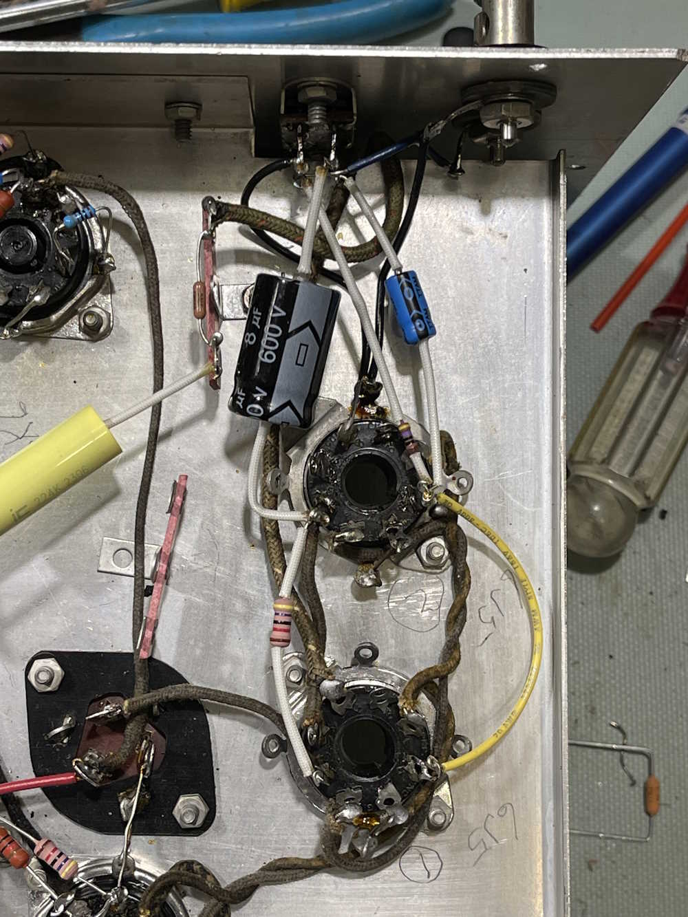
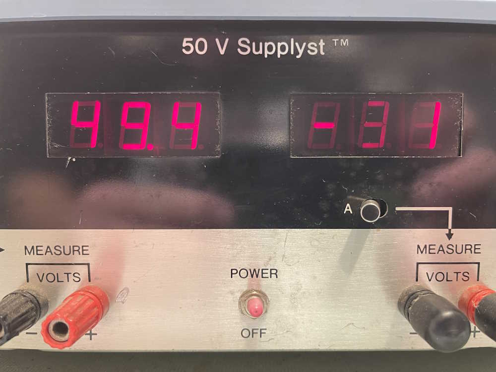
I decided to check the 5V lines for both sides, since I now know there are two individual rails. The working side is ~5V. The non working side is down near 2.6VDC, and the input is about 4.6VDC. That’s certainly wrong.
Time to pull it out.
There’s some crusty flux under the device, I’ll clean that off with some alcohol. Now the input reads about 12VDC, which is probably fine as it’s input is unregulated. I decided to pull the small capacitor beside the regulator, it wasn’t shorted but it had an ESR of 28Ω so it’s dry. I’m sure the other one is too. I have a couple of 4.7μF parts laying around, I’ll replace both.
Something is drawing the voltage down, but is it the regulator? I’m not sure - I didn’t feel anything getting hot during testing.
I’m going to go ahead and check all those transistors for shorts, and try to do some comparative measurements with the other side. I also have some LM309H parts laying around somewhere, it’s just a matter of figuring out which bin I put them in. Stay tuned for part 3 and hopfully a full diagnosis.
The last thing to do with the Heathkit AG-7 on the bench is make the power supply connections. Since I didn’t want to put any components on the filter capacitor cans, the parts that would have ridden there are now on terminal strips and need to be run to their respective terminations with wire. That just involved some…well…wire.
There’s a little bit of wire sticking out there that I need to remove - it was originally a run that got deleted by the parts being moved. For now, it just hangs in the air. That’s all of the connections, so on to the check.
During checking, I found three errors.
2 of those errors were simply no-solders where I had unsoldered a terminal to remove something and didn’t hit it again later. These were both lugs that had components that were moved, so I just never went back to them.
The big error was that I made an assumption. On the Hi/Lo switch, there are a number of connections. The schematic shows this connection as a picture, and I dutifully wired the switch according to the picture. Well…the picture showed certain connections at the top, and with the chassis flipped over I wired it just like that. Turns out the top of the switch is actually…the top when it’s sitting upright when you’d use it during operation. That was an easy fix, a couple of connections and a gold star with derp on it for me.
Nothing else was amiss, the schematic now matched what was in the unit. Time for the smoke test.
No smoke, and I have a signal on the scope!
The signal is clean, so the oscillator is driving itself at the proper rate. That’s what I wanted to see!
Next up is final adjustments, final thoughts, and a bit of an interesting find. Stay tuned!
It’s time to start putting parts back in the Heathkit AG-7. I’m generally trying to follow the OEM layout, but I’ve decided to add a few terminal strips for quality of life, and to get parts off the filter capacitors.
The filters are good at this point in time, but eventually they will need to be replaced. Not having anything other than wires on their lugs will make it a lot easier to do this replacement when the time comes. I don’t have any qualms about doing this kind of mod, as I want the device to work. The only reason I’d re-stuff a can of filters is because space is at a premium, which it is in this box. That’s a future post, however!
Here are the rebuild pictures, in no particular order. The only thing left at this point is to remove a couple of mods and to wire some of the filter capacitors back into their new connections.
I hope to have this completed and ready for test by the end of next week. Stay tuned!
Often, when working on an older device, you’ll find part replacements and modifications made by a previous owner to accomplish something. While it’s not always obvious what those modifications were doing, it’s often necessary to remove them in order to restore the device back to OEM functionality.
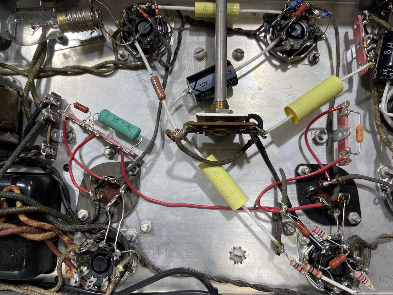
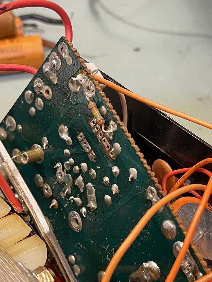
Case in point is with the Heathkit AG-7 I’m rebuilding. Take these two items:
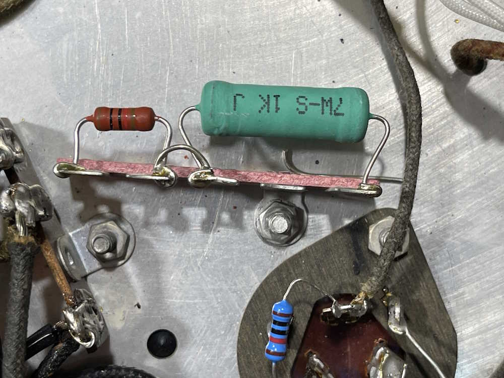
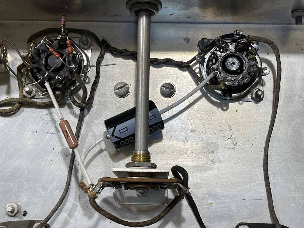
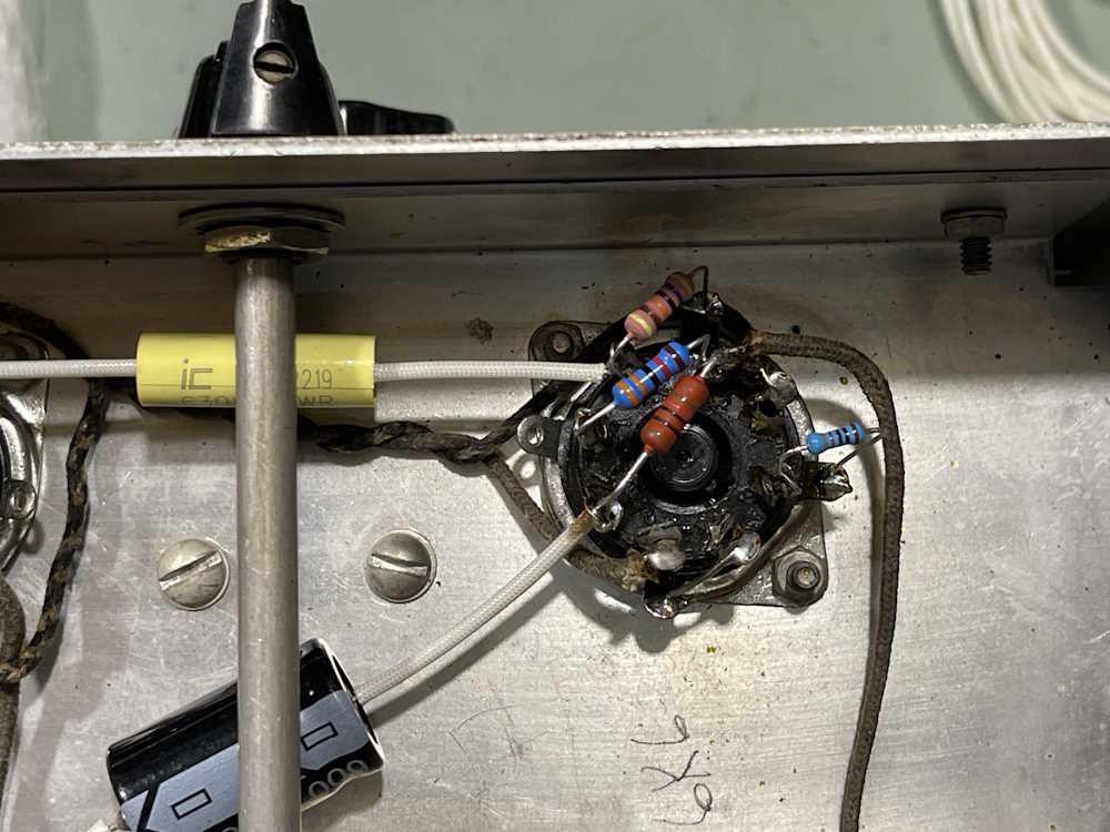
This is the output adjust potentiometer. Note the 100kΩ resistor.
This is the output Hi/Lo switch. See that jumper wire? There’s also that white telephone-style wire that goes from the switch to the output. This would have been cloth coated originally. Not shown is a messy ground connection here, where they simply twisted three pieces of wire together and soldered it in mid-air.
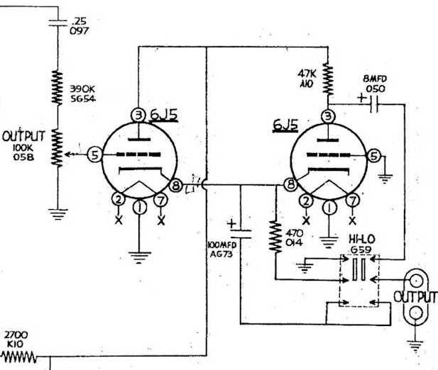
Here’s the schematic for this portion of the device:
You’ll notice the absence of a 100kΩ resistor across the output pot. I have to assume this was to change the linearity of the output for some reason. There’s also a jumper on the switch, but it’s on the bottom and jumpers the lower half together - not catty-corner like the previous owner had. I’m not sure what they were trying to accomplish with that.
edit: Eric HABETS from LinkedIn suggested that to correct DC offset in the output of this device, it would be advisable to put something like a 100k across the output of the unit, and that the switch is Hi-Lo Z (Output Impedance.) Perhaps that’s what the original owner was correcting for, and they set the output up for their particular telephone application.
These mods come out, and it gets put back to the way it was. Hopefully, this will reduce the amount of smoke that comes out!
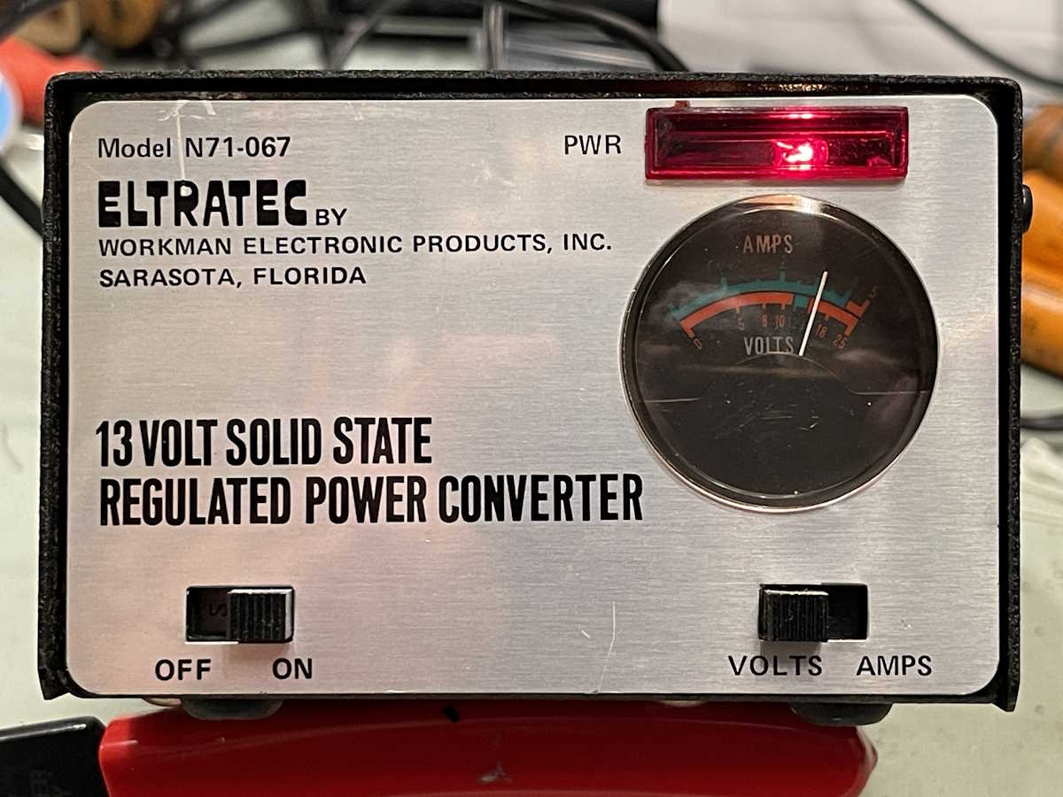
On the bench while I wait for parts for the Heathkit AG-7 is this Viz WP-705 power supply. This came from the TUSCO show earlier this year, and while I didn’t need it, the price was cheap. The vendor originally was asking half a bill for it, but when he plugged it in and the ammeter didn’t light up, he reduced it to $10. I took it for that, just because a nice linear supply is always useful.
Viz is the “company” that took over RCA’s test equipment division as it was phased out. RCA contracted out this division to start with, so it was more of a rebadging than anything else. The company that took this over, Jetronic, was already one of their big contract manufacturers, some new paint in the logo area and Viz was born. It still looked just like the RCA device, was full of RCA parts, but had a different name on the front.
Jetronic Industries Inc. appears to have continued until 2000, when they filed for bankruptcy. It was a shell company for some time, before finally being dissolved and removed from records in 2012 for failing to file necessary reports with the SEC. That’s all there is to their story.
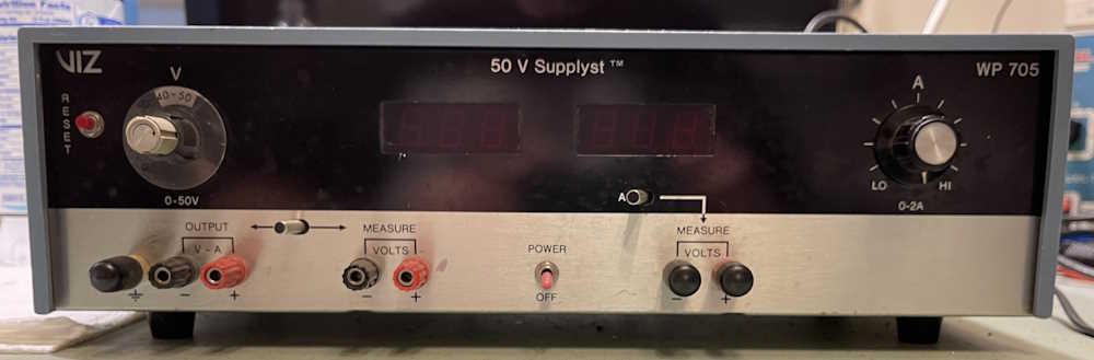
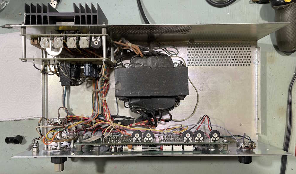
Here’s the device in question:
This is a single-output power supply with the ability to use it’s internal meters as external meters - that’s quite unique. It’s part of a series of supplies, with each successive model number adding more features and outputs. This appears to be a middle of the series unit, or bottom of it’s tier depending on where you place it in the model stack. It’s 0-50VDC, 0-2A, and is a linear device built out of discrete components with only the displays having ICs in their circuit.
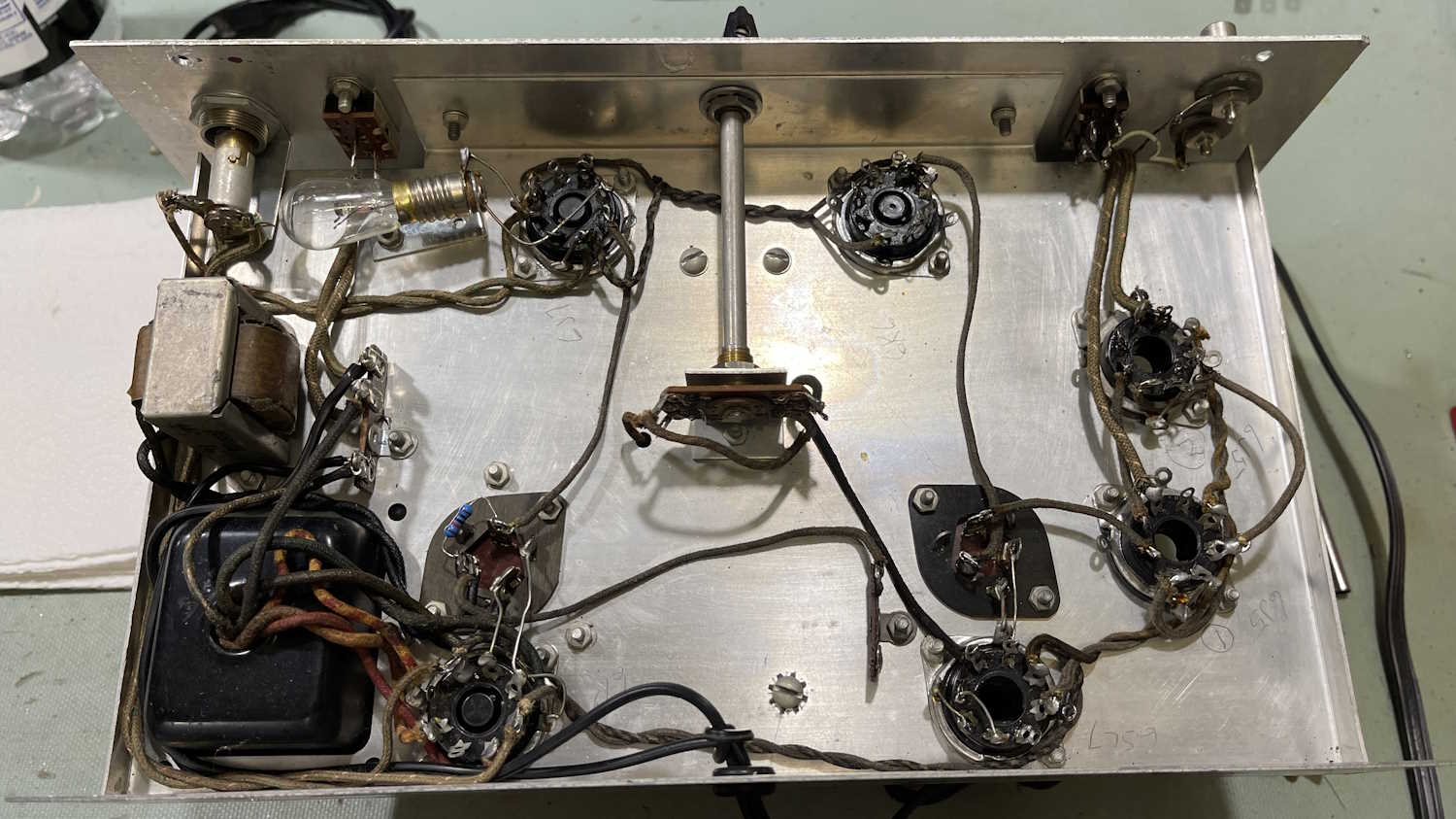
Inside is a big chonky transformer:
So what’s wrong with this? When I bought it, the ammeter wasn’t working at all. That is, the display was dark. When I put it on the bench, the ammeter lit up, but the display rolled all over the place and didn’t respond to anything. It was like whatever A/D this thing was using was bad and just floating.
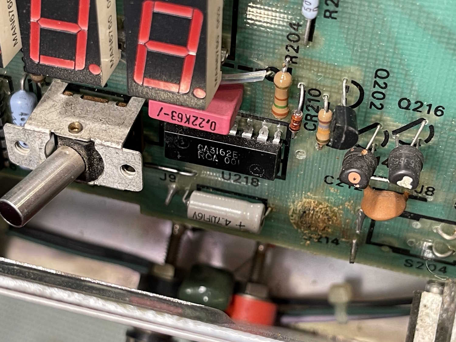
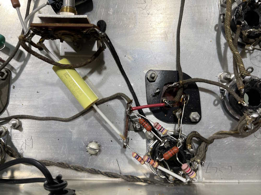
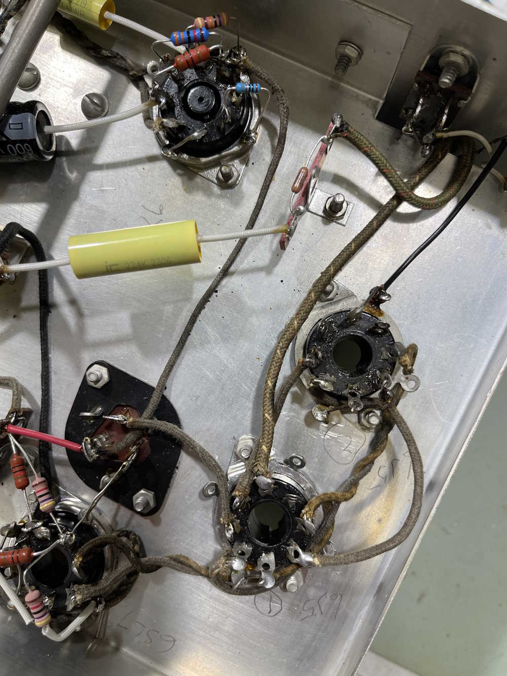
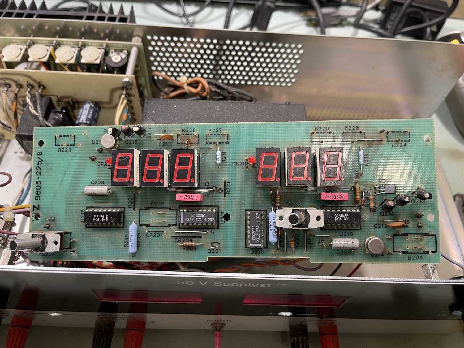
What’s on the board?
The unit uses two older RCA chips to do it’s work - the CA3161 and CA3162, which are a driver/converter pair. There’s some glue circuitry as well, which looks like it’s for the display select during driving. As you can see, there’s some different-shape transistors on the board, as well as some ECG parts with a much nicer (i.e. later date) marking, indicating that this device has had some work done to it in the past.
Since there’s not a whole lot here, and the display is still scanning - that kind of points to the CA3162 A/D converter. Unfortunately, with NTE being gone, there are no more new replacements, but NOS devices exist. It’s just a matter of finding one.
I have a schematic on order, I’m going to study that for a bit before proceeding just to make sure I’m not missing anything. Stay tuned!
In the last post, I checked a few parts and found that pretty much every resistor (that I could measure in circuit) was out of tolerance, in a bad way. Seeing as how the device stopped oscillating, and started smoking, I decided that replacing everything was the best course of action.
I’m trying to save the old parts for later testing purposes, so unsoldering with intact leads is a must. That does tend to make it’s own problems, something we’ll discuss later on.
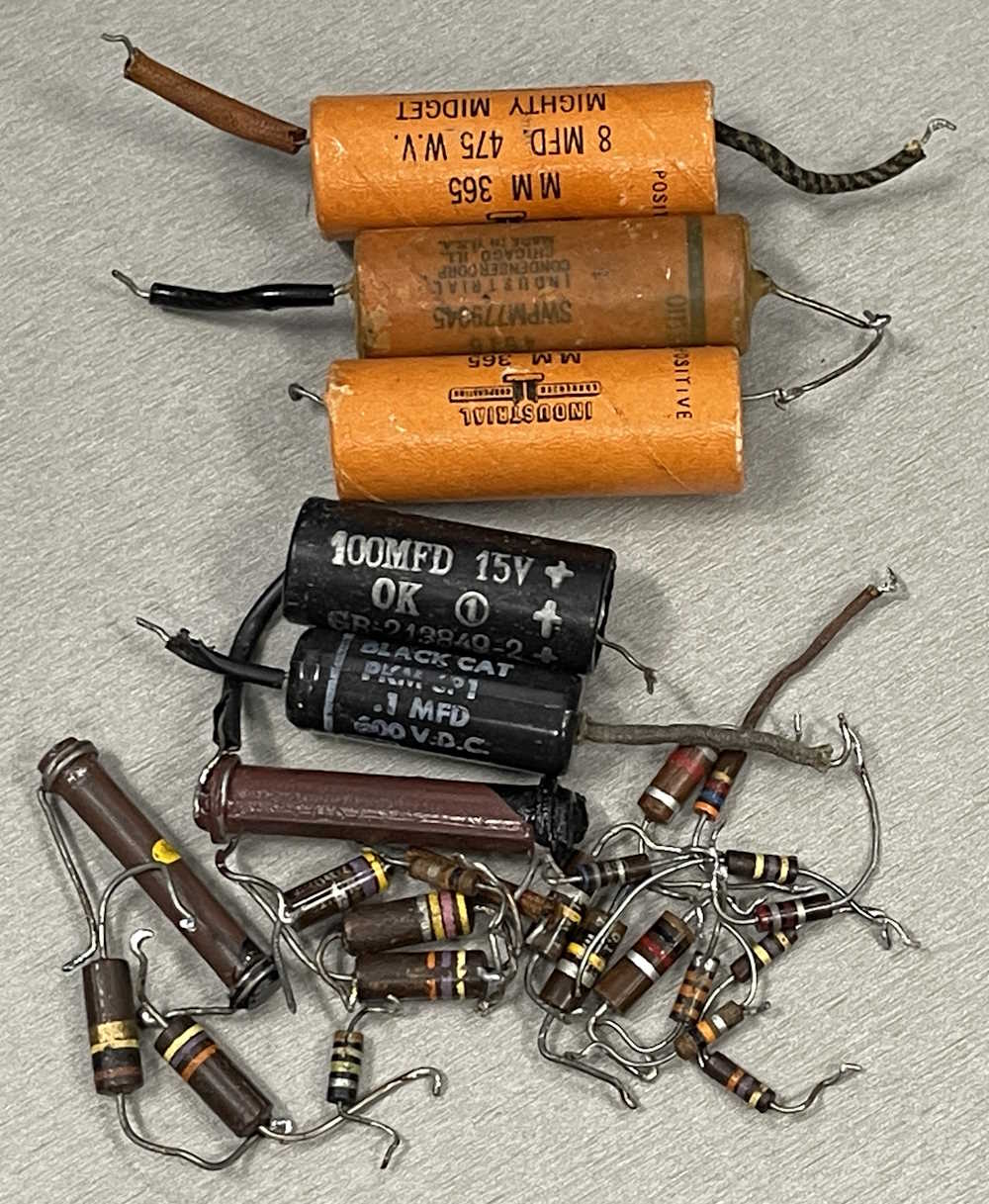
Here’s what I recovered (save the 10k removed in a previous step):
The chassis is now empty.
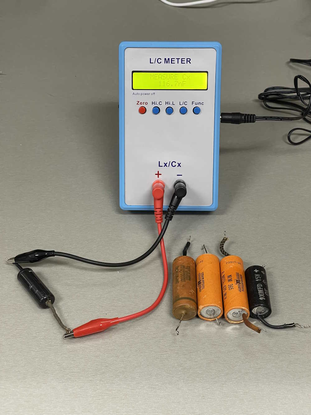
For testing, I just grabbed my scope-meter and a capacitor checker. I’m not really worried about ESR or leakage here, they’re just old and probably have issues with both.
So on to the good stuff. How bad do the parts test? Well, that’s the fun part. Most of them are ok-ish, even the ones that read substantially higher in circuit. The 100k in the previous post? It’s back to well within in tolerance range.
What happened here? Carbon Composite resistors change value over time because the carbon grains disassociate with one another, and they collect moisture. I hit these with some high heat during the desoldering process, which probably drove out the moisture and brought them back near tolerance. I suspect if I left these alone for a year or so, they’d be back to what they were. Perhaps I’ll segregate them and do a follow-up next year.
Of particular note was that 270Ω part that read 2.6kΩ. While this looks brown to me under normal lighting, the camera shows it has more of a red hue. This guy must have been pretty warm over the years and the color simply faded. It’s actually marked 2.7k.
Next up is actually placing new parts. Check back soon!
Disclaimer: This involves working with high voltages and high currents, and is a device that you’re going to plug in to a wall outlet and leave there. Make sure you’re comfortable working with this kind of stuff before proceeding! This is a guide and you need to know what you’re doing beforehand. If you don’t - don’t! Mistakes will destroy property and kill you.
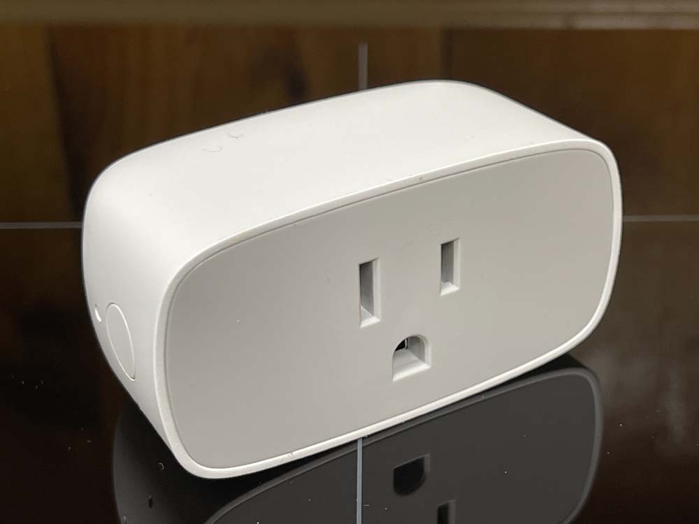
Ikea is one of the oddest stores I’ve run across. Known for their flat-pack furniture, they also have a line of relatively friendly and cheap technology devices that operate on common standards. One of these devices is a smart plug called the Inspelning (translation: recording.) It’s available in multiple countries with different outlet formats, but the one I’m going to be concentrating on is the North America version.
This is a generic ZigBee compatible device that offers both remote control via their own hub and other compatible devices, as well as providing both power consumption and line voltage monitoring functions. It exposes these via Ikea’s own application, or by entities within Home Assistant or some other smarthome system. I’m using Home Assistant, and these have no issue integrating and exposing all information.
So what’s the modification?
These are cheap devices at ~$13 - and you’re not going to find something with a power monitor that’s much cheaper. But…they can also turn on and off, which means if you’ve connected something that relies on being powered on all the time, having an accidental trip that shuts it off could be problematic. My modification is to make the device permanently on. This also has the effect of preventing premature power supply failure, which can cause relay issues and seems to be a common failure mode with smartplugs in general as the components inside are as cheap as you can get. I want a power monitor, not a remote plug, and this is a way to do it.
First thing is to get the device open. These are relatively benign, and are just clipped together. There are 6 plastic clips - two on the top and bottom, and one on each side. I don’t have any pictures of opening because it’s not a picture friendly process, but here’s how I did it:
You’ll need some sort of opener tool. I used iFixit’s blue spudger tool to pry a bit of the top of the case back at one of the clips and then pry up the gray plastic face. I then used one of their “guitar picks” to hold it open while I used a butter knife to pry-pop the rest of the face off. If you’re careful, the gray plastic should deform enough to release the clips on the sides.
I tried using the spudger to go all the way around, but the sides are simply too curved to get a good entry point, and not flexible enough to pry. I wouldn’t try this with a device that’s been around for a while, but a new device should have enough flex left in the plastic that you’re not going to break anything. Try not to insert anything in the lower part near the ground hole, as there’s a piece of circuit card that sticks up in this area.
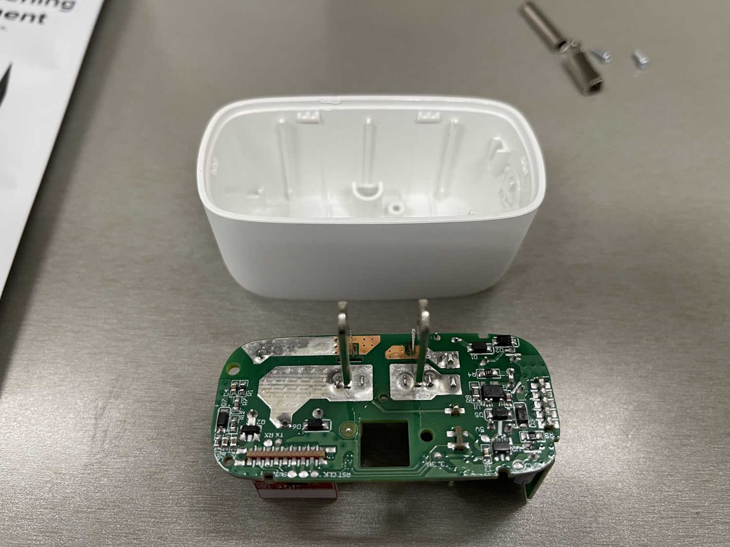
Once the face is off, it’s relatively simple to access the circuitry.
First, remove the ground lug assembly. This just falls out, as it’s set in a hole. Set it aside. This isn’t connected to any of the circuitry inside, so if you needed a two-prong device to replace something like an old X10 two-pin appliance module, this is the way you could do it. I don’t suggest you do this, however, as modern outlets are all grounded.
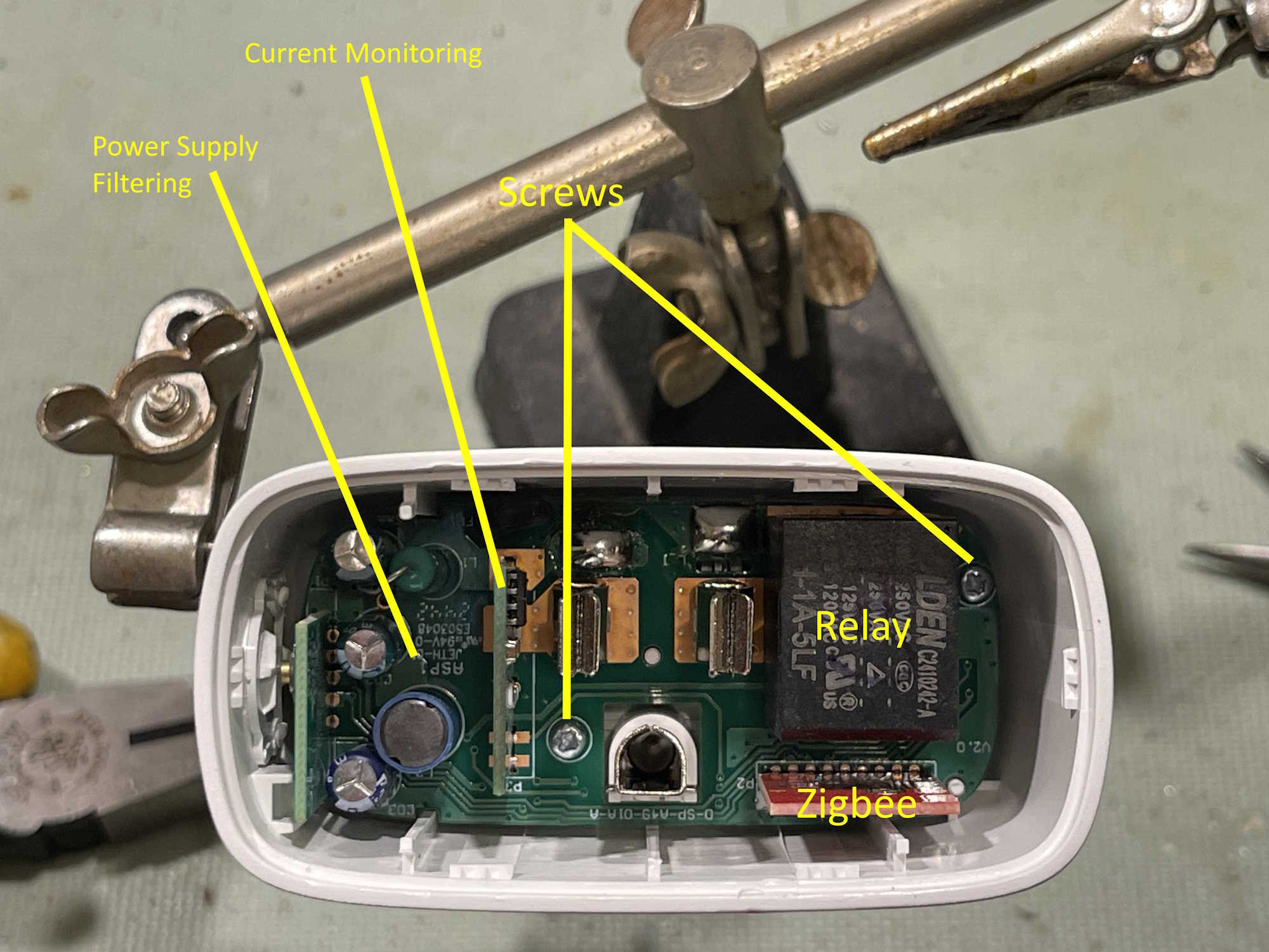
I’ve named the various parts, but we’re not really interested in anything but the screws. These are extremely shallow philips screws, so you’ll need something to fit them. I didn’t have the right kind of driver handy, so I just used a thin blade flat to catch and back them out. Don’t apply a lot of force to these, they’re really cheap and wanted to destroy themselves.
The other parts here are the relay itself, the zigbee control board, the current monitor board, and the power supply filter capacitors. Chances are the latter would need replaced if you encounter a situation where the relay chatters or becomes unreliable, but that’s not a given and outside the scope of what is being presented here.
Push up on the plug tines to move the board to the top of the case. There are little pips that help keep in inside, you may need to gently wiggle to get it out. Avoid pulling on the control boards.
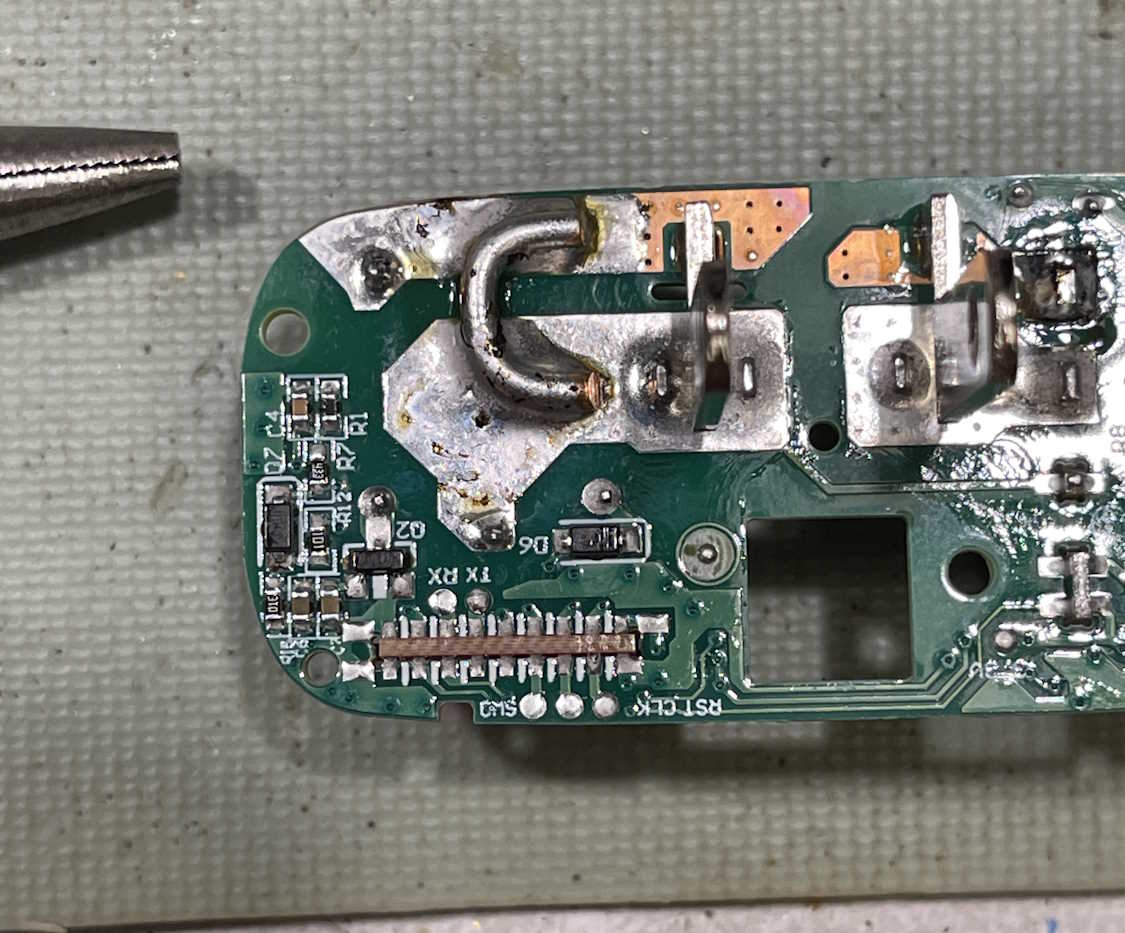
The back of the board reveals what we’re after.
There are two large soldered pads on the left of the board. This is the area that the relay connects when it closes, and connects the hot tine to the hot receptacle on the front of the board. The current monitor is in the neutral line, and is always active so it doesn’t matter if the plug is “on” or “off.”
We’re going to jumper across the hot line pads to create an always on loop. You can still activate the relay at this point, but it will do nothing.
CAUTION - you’re working with something that’s going to be plugged into the wall and will be conducting a potentially large amount of current. Make sure your connections at this point are well-soldered and using a properly rated gauge of wire. A half-ass connection won’t do it here.
I’m going to use a piece of 12ga solid from a strand of THHN. I’ve cut a section and bent it around a pair of needlenose pliers, then trimmed it.
Why a U-shaped piece? Mostly to give plenty of area to solder. You don’t want this thing coming undone inside the case, and the solder is going to be part of the 120VAC conduction area. Err on the side of caution here, give yourself plenty of area that’s soldered to and touching the pads.
Make sure you have a good fillet all the way around the jumper.
Note - you’re going to need a decently hefty iron to do this - your little 20W SMT iron won’t cut it. A good 35W with a flat tip should work, but I used my 80W iron. Make sure your wire is pre-tinned and put a little solder down first. It will probably take a bit of doing to get a good placement, but make sure your wire has a good fillet all the way around, and is centered well in your pads. Don’t let any solder or wire drift off near components.
This should be good for at least what the relay offered, probably more since that relay is about as cheap as you can get.
Assembly is, of course, the reverse of disassembly. Install the board, the ground lug (make sure the flat is lined up properly with the area meant for it,) the screws, and snap the face back on. Do a quick ohms check between all 120VAC connections to verify there’s no shorts, and if good - plug it in and connect it to your smart devices monitor system.
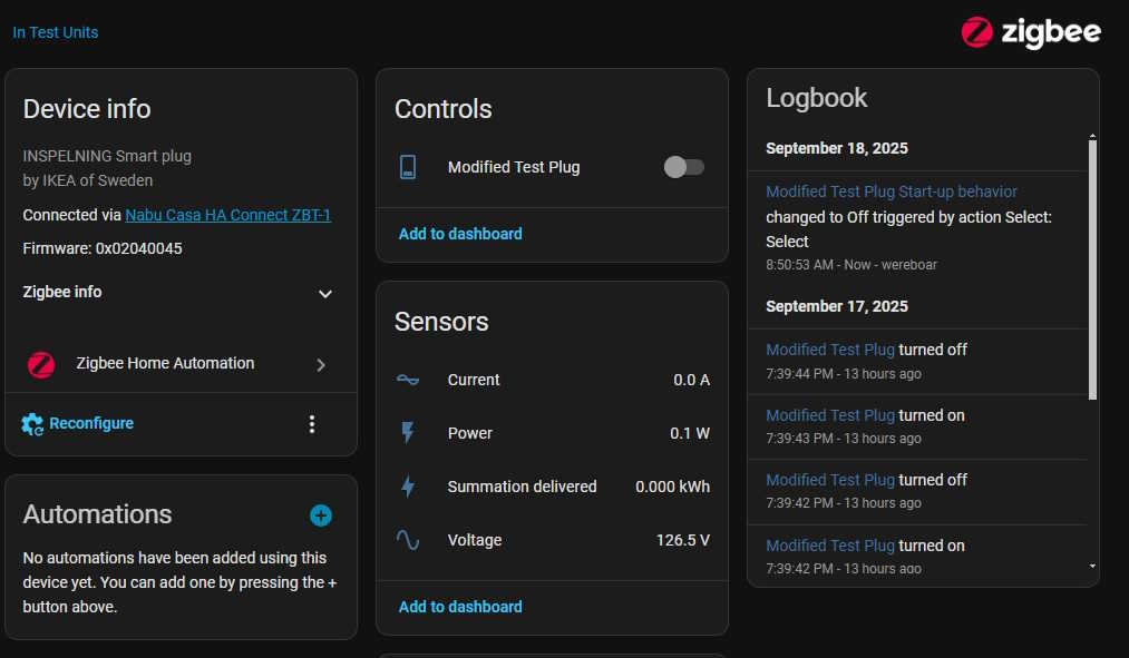
I added mine to my test devices area and got this:
It’s reporting no current draw (other than the dithering these show) and is correctly reporting line voltage. The plug is not “on” as this point, although you can clearly see it still understands the button press. I suppose you could use this as some sort of scene selection if you wanted.
That accomplishes what I set out to do. While there are a few companies that provide non-controllable devices that do the same thing, this is by far the cheapest way of doing it.
One final note, Ikea has announced that they will be discontinuing the ZigBee devices at some point in the near future, in favor of Matter. I assume that just involves replacing the control card, but who knows. Get them while you can!
Disclaimer: Again - This involves working with high voltages and high currents, and is a device that you’re going to plug in to a wall outlet and leave there. Make sure you’re comfortable working with this kind of stuff before proceeding! This is a guide and you need to know what you’re doing beforehand. If you don’t - don’t! Mistakes will destroy property and kill you.
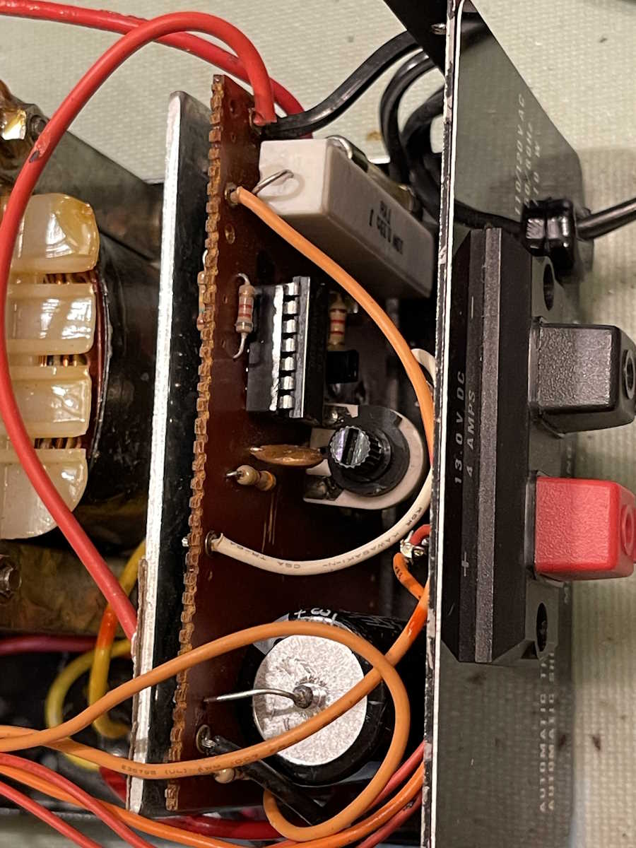
After poking around in the power supply for a little while, it was apparent there was something going on right around the LM723 and it’s driver transistor. Since one had to be pulled out to test the other, I pulled the driver transistor. It’s shorted C-E, so that’s the problem - the LM723 can’t regulate a voltage when the regulator’s driver is driving the output to the max.
That’s an easy fix, it’s a S8050 transistor. I had to place an order for some other things, so I ordered a batch of transistors.
It was easy enough to install
However, since the LM723 probably was quite stressed from this failure, I decided to replace it as well. I just cut it out and pulled the pins from the solder pads, then removed the solder with wick. That 1970s phenolic board smell! It’s going to get socketed just in case. (Finding these in DIP is getting kind of difficult!) This was a device where they only left copper where it was needed, so it came out easily.
Since the big filter was quite old, I replaced it as well. Here’s a shot of the completed and re-installed board:
And, it works!
So what all was replaced?
The S8050 driver transistor for the series pass regulator.
The LM723 Regulator IC
The main filter capacitor.
I did dial the output back a little to 12.8VDC, just because I want this on my bench for other things.
A relatively easy repair, but there’s not much in this thing to go wrong. Next up is the Heathkit AG-7 that’s been kicking around for a while - it’s going to need more than I thought, as well as a Viz (RCA) power supply with a designed-in fault.
So, this item literally followed me home from the Cincinnati Hamfest.
Seriously.
I was talking to a guy about a Simpson 260, and he asked if I was interested in a radio. I said no, I had an old coffin TRF in the queue. He picked this up and handed it to me and said “If you do something with it, you can have it.” I said “I promise it will go on the bench, but nothing more than that.” Deal done.
So what is this thing?
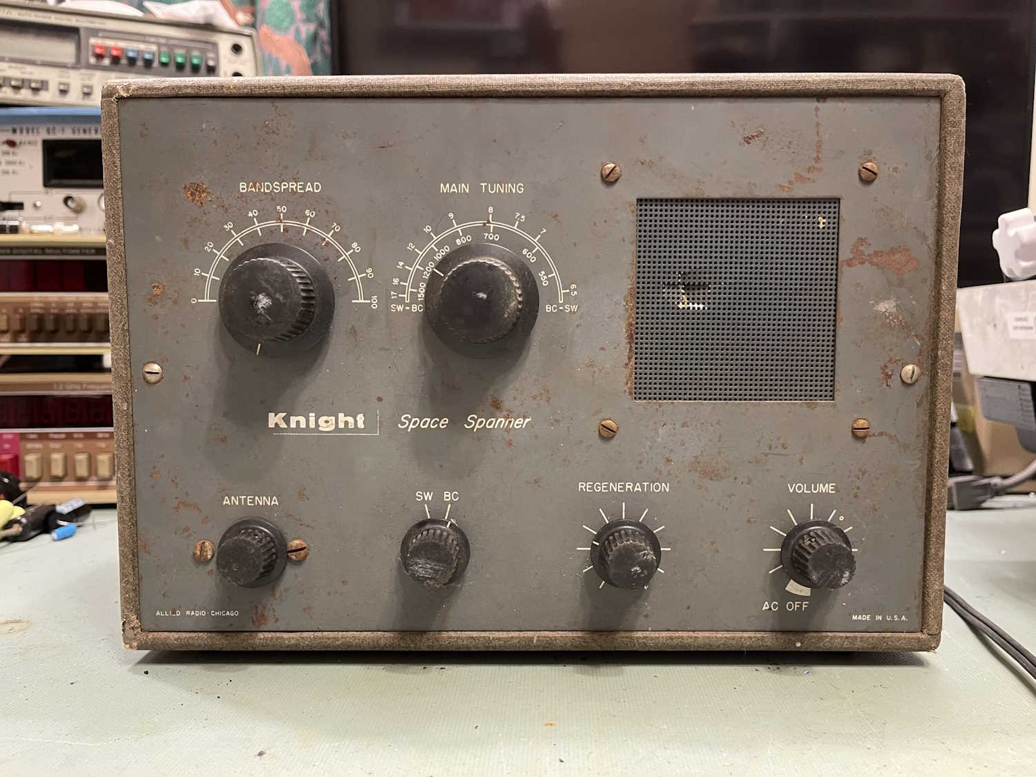
It’s a radio from Knight (Allied) called the Space Spanner. It covers broadcast and shortwave bands. It’s based on an old design called a regenerative receiver - essentially, the RF is re-amplified before being detected, so hopefully you get a stronger output with less active components. It’s cost-reduced before cost-reduced was a thing, and was obsolete by the time this kit was made. It was cheap, however, and allowed a new kit builder to get something and cut his teeth on it for not a lot of cash.
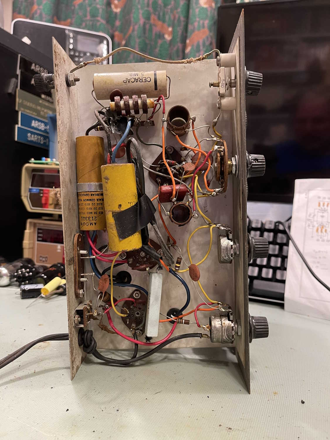
It’s in fairly poor condition, and probably sat in a garage after the builder moved on. Everything is there, however, so that’s a plus. The cabinet is a plastic-wrapped wooden case made from plywood, and is actually a fairly nice cabinet. It’s very dirty, however - scrubbing with 409 barely made anything except blackened towels from the dirt. (I’ve read the cabinets for these were made by a luggage company.)
Inside, the chassis shows signs of being modified over the years. There’s a giant capacitor stuck in there, and it’s attached to the final point on the original filters. I have to assume the original is bad, and the person just stuck a 100μF in there because that’s what they had, and it worked. I’ll know more on that, later.
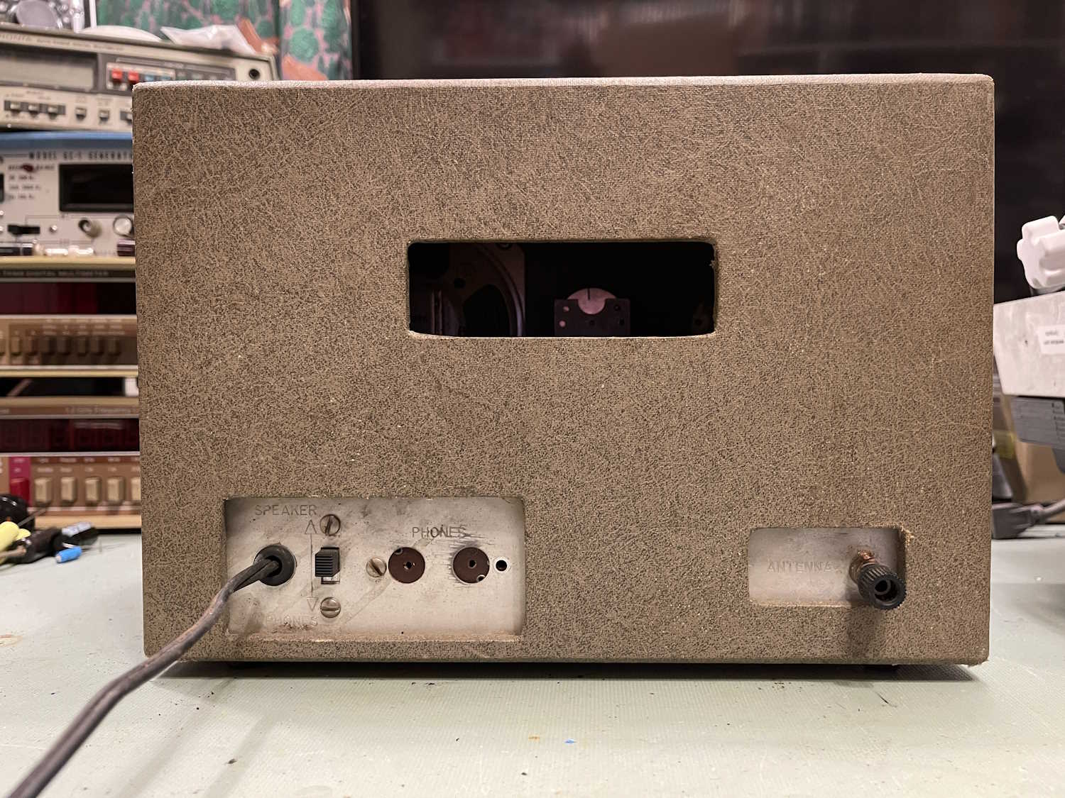
The antenna terminal is loose and the plastic portion is locked open. That’s no big deal, and a pair of needlenose fixed both the loose screw and the locked connection. Tubes are all there, and most capacitors are disc. I don’t see any real reason for concern here, so into the isolation transformer it goes. Probably should dim-bulb this, but eh…I like living life on the hot edge.
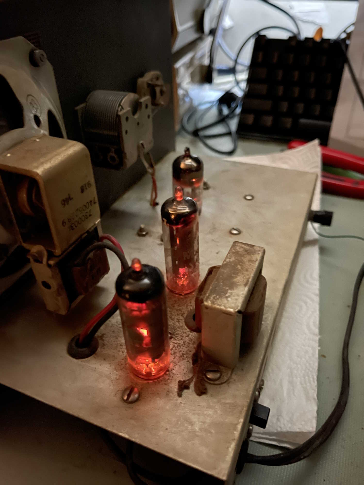
I got a little noise out of it, but nothing else. A tube wiggle made lots of noise, so I turned it off and gave all the pots and tube sockets a few drops of DeoxIT. After a good cleaning, I put the tubes back in…
It came right to life. After messing with the controls, I was able to get most of the strong local AM stations with a short piece of wire. So, the device is working, which is pretty cool.
So, what next?
I think I’m going to do a basic restore on this - new resistors and a new filter. There’s not much else, all the other parts are disc capacitors save the ceramic cap at the top, and it looks good. I do need to figure out what’s up with the antenna control, it seems like those spacers are too long and the knob won’t go on properly. I know it’s the correct knob because it both matches what is on the rest of the unit, and other images show this knob. Maybe some shorter spacers are in order, who knows.
Anyway, this is a really cool piece of old tech, and deserves a chance to live properly. Stay tuned, more on this unit coming later, rather than sooner!