Friday turned out to be a just slightly damp day at the show, we had a little rain but it cleared off quick. We toured the flea market, and saved the buildings for Saturday due to the forecast of heavy rains. The steak tips and mashed potatoes vendor wasn’t here this year, so bourbon chicken and a banana milkshake subbed in it’s place.
This year, the mobile AM CB stuff was almost all gone save a few units here and there. Hobby-level test equipment, i.e. the EICO/Knight/Heath/etc. was almost not present, save for a bunch of those crappy RF generators that no one really wants - the bridges and tracers and things are pretty much no longer for sale. At least, not at Dayton. Of course, the piles of plastic radios and old televisions are long gone, and even the big boat anchor radios are vanishing. I think I saw maybe 1 Hallicrafters S-38 unit for sale…
Things are changing, but there was still a lot to see:
A nice A-K speaker.
A basket of Apples.
Just some audio stuffs.
A nicely restored cathedral radio.
Choke the Chicken…not here please.
An old Data Precision meter.
Many DEC Rainbow computers.
New, old-stock desoldering irons.
My favorite brand of tools?
Designed for butane flow measurements.
Some tunes for the ants.
No idea what this model was.
Someone's pride and joy, dumped in a bin.
I eventually took the scope for $1.
The old way of measuring standing waves.
Just some random HP things.
Ok, if you insist.
Loudenboomer!
Some info on the Loudenboomer.
Would you like to play a game?
It's not tourist season without a thumb.
Some military equipment.
Telephone B.C. (Before Cellular)
How many of these were made?
Moto comm analyzers.
A really nice condition scope.
Some old computing horsepower.
A really old opto counter.
This scope was in bad shape elsewhere.
Parts. I took a few transistors.
High voltage?
Used to be piles of this stuff.
These are vanishing as well.
Some more radios.
And some more radios.
A scope that was part of a school course.
Even if it was good, this showed bad.
Some sort of receiver.
A tape deck. Friend wanted it, you carry it!
Lots of these, no one wants.
Some of those funky round speakers.
I took the Sabtronics unit for a sawbuck.
Semiconductor testing devices…in peach.
A Shango Special.
I have no idea.
A table full of stuff.
Hallicrafters SX-62.
It's a radio that's a table that's a radio.
Teletypes for your 110 baud needs.
A cool old terminal.
daytonf26-terminalsettings-wereboar.jpg
The only signal tracer I saw.
A giant TRF radio.
A nice looking TRF unit.
Warm soda and melted candy anyone?
Surprising, more W-J stuff this year.
Some W-J stuff.
We spent pretty much the entire day, heading out at 4:45 a few minutes before closing. We went Saturday as well, but I skipped out on Sunday.
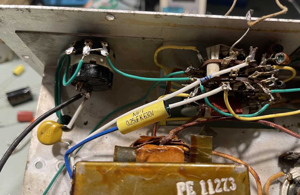
Continuing on with the EICO 950A, the components near the power input need to be changed out, especially the capacitor used as the across-the-line component.
The orange drop is being used as the across the line cap. While this would have been acceptable way back when, it’s not acceptable now. We have specialized capacitors for this purpose, and one goes there. I’m also going to clean up the power input lead to the transformer, and it’s going to get a new line cord. The 470K resistor will go, and there’s a hidden 270K on the switch that will come off but not get replaced just yet as the parts I bought decided to hide from me.
There will be a 270K placed here, eventually.
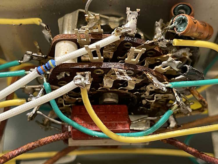
I took the time to remove the rest of the junk from the power supply:
And the entire thing is starting to look better.
Next step is to tackle the resistors on the switch itself, as well as those two capacitors buried inside. I also need to consider where things will mount on the supply…the OEM used the tube socket as tie points for all parts, but I’m not sure I want to do that. I usually like to get the AC off on it’s own. We’ll see.
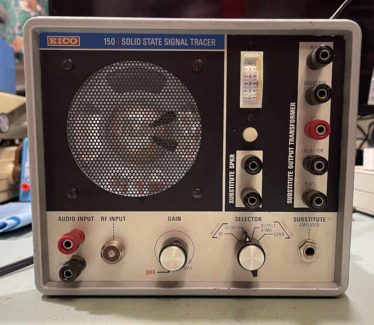
The EICO 150 signal tracer that was recently on the bench works, but it has some other problems.
Mainly: Noise.
The output is very noisy, and I want to track this down. I thought about putting this aside until later, but it has me intrigued and I want to get to the bottom of it.
This series will deal with isolating and tracking down the noise present in the unit - noise that is present on the output as popping and crackling.
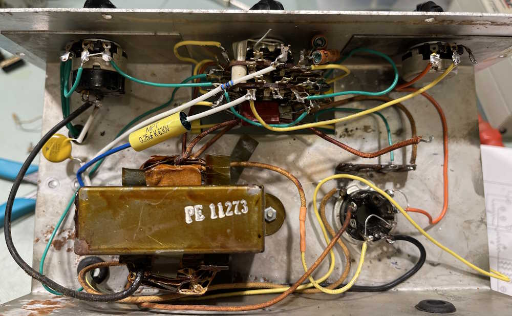
The EICO 950A currently on the bench is a mess, and there’s just a lot to remove and re-wire.
The power supply area looks a little cleaner.
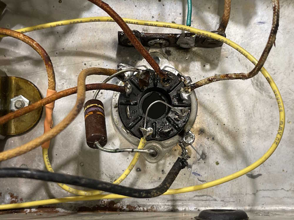
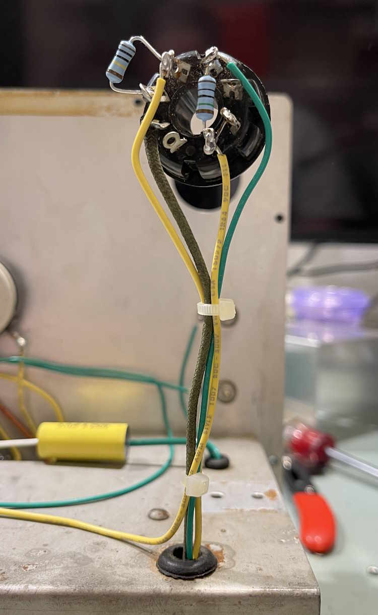
The leakage test lamp was mounted in a manner that required you run wire up and around. I moved that so the terminals now pointed towards their connections, and cleaned up the ground enough that it took solder as the original connection just peeled off. That took some doing with scratchy items…
The eye tube socket was equally messy, but cleaned up sort of ok.
That’s all for this round, there’s still plenty to do on the bottom, and a few parts poking up through the top that will need to be addressed. Stay tuned!
This was an interesting device to repair, but it’s a good example of why you have to expect the unexpected when working with older equipment. Never assume that what you’re going to find is the same as what you’d find in a new device.
For the most part, the device was functional but needed all the small capacitors replaced. I went one step further and replaced all of the capacitors, because why not? You’re in there, just do it. Capacitors are cheap and will extend the life of the device. Resistors were checked, most are within or close-enough to tolerance that I didn’t worry about it. The biggest issue was the speaker.
Small value parts probably could have been left in place, but I’ve seen some of the styles in there short out. Again, they’re cheap, replace them.
Diagnosing the EICO 150
Initially, I looked at the output transformer because the color-codes on the wires were wrong. While the original kit builder installed it correctly, it still took a hot minute to figure out what was going on. I took the opportunity to extend the wires on the transformer to reduce stresses on components, and re-installed it according to impedances.
The transformer was fine, so checking the speaker was next. DC resistance was really low, and impedance was also low enough that it was mostly zero. Speaker was shorted. Why? Not sure, perhaps age did something, or maybe as Mr. Eric HABETS from my LinkedIn crowd suggested - someone used it as an external speaker and blew it out. The world will never know.
What I do know here is that there’s still some issues within the output side of the unit. Vc should be zero, or close to it - but it’s not. There’s also the noise in the unit. Either a resistor is bad, or a transistor is breaking down under load. I have new transistors for the unit, so I will probably open a new project with this device and replace the remaining passives and clean up some of the messy wiring on the bottom.
This was a fun, interesting repair. I’m hoping perhaps I can find some transistor output transformers, or a complete unit at Dayton for comparison checks. Stay tuned, there will be more with this device later.
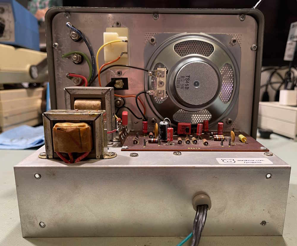
After going through this unit, replacing the capacitors and wandering around the incorrectly built speakers, we arrive at the actual defective portion of the unit: the speaker.
Obviously, I can’t just order a new one from EICO, that company having been dissolved many years ago. As this appeared to be a regular 4” square speaker, I found one that looked to fit. In this case, the Philmore TS45, a 4” 5W mylar cone unit was purchased.
It went in without issue, and fits the original mounts.
Of course, even this cheap speaker outstrips the capabilities of the tracer, but it is what it is. You can see into the unit from the front, which is kind of cool.
I had some suggestions to backlight the device. I’m thinking no.
The speaker works well. Since this is an aural device, I have a couple of videos of the device working coming up in the wrapup post. Stay tuned!
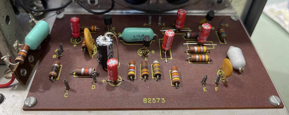
The small value capacitors in the EICO 150 need to be replaced as well. Yes, this should have been before the testing post, but…this little wereboar hasn’t had enough coffee yet, I mean I meant to do that…totally meant to do it this way!
There are three small value capacitors in this unit. Two teal-colored 0.22μF, and one gray 0.01μF. The teal parts are interstage and blocking for the meter, the 0.01 is input blocking for the RF side of the unit. While these parts seem ok, I’ve had other EICO devices where similar parts were a dead short - so they go.
Here’s the before shot:
And the after shot:
For the input blocking part, I used a film 0.01μF at 400V, same value as the original. The other parts are WIMA 0.22μF at 250V parts, similar ratings to what was there.
The one on the far left is the meter input block. It has a 10k in front of it, but I think that is probably going to have to be changed - you really need to drive this thing loud to get any noticeable deflection on the meter, and the meter is just a visual indicator, not a measurement. A mechanical eye tube, so to speak.
That’s all for the internals, next is the speaker since it’s shorted. Stay tuned!
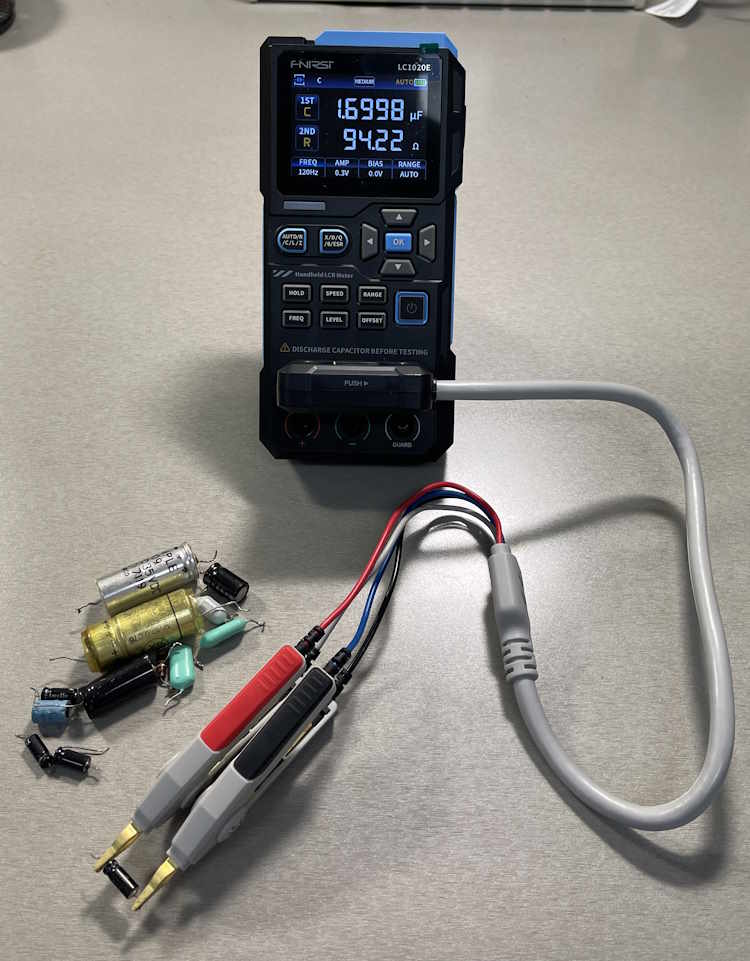
As I have a decent capacitance meter with ESR capabilities, I decided to see exactly how bad the removed parts are. For the test, I’m using a FNIRSI LC1020 that I’ve shown to be more than accurate enough for hobby purposes, and you can read my analysis at this link.
I tested the parts in no particular order save from smallest to largest. These are all going in the junk bin, so there’s no need to mark them as to what they are - I can always retest if need be, but these won’t be used again except as other test parts.
For the following chart, the first column is marked value. The next two columns are values read at a particular frequency, in μF. The last two columns are ESR at a particular frequency, in Ω.
The smaller ones have fairly high ESR at low frequencies, with that decreasing as F increases. That’s expected - they’re still shot, but low value parts generally have higher ESR. Larger values, like the filters, were fine - but old. They got replaced as a matter of course.
For the smaller values, these were generally good save for the fact that I’ve seen those little teal parts short. They were replaced with good quality WIMA capacitors, or in the case of the 0.01μF, a new axial film.
A note on the 0.01μF part - the meter refused to stabilize when reading ESR on this one. I assume it’s probably going bad. Since it’s the input blocking capacitor for the RF side, it’s probably for the best that it was replaced.
There’s still some work to do as the capacitors actually need to be replaced (yeah that should have been first!) and then the speaker install and test. Stay tuned!
In the last part, I noticed that the output transformer appeared to be installed incorrectly in the tracer. While the color codes were indeed wrong, the kit builder did install it correctly. This was verified with an impedance check revealing about 136Ω on the primary, and about 5Ω on the secondary. That was measured at 1KHz, and is fine for a transistor output circuit. It was reinstalled in the correct direction.
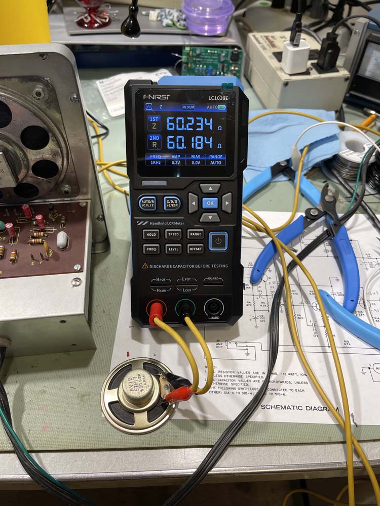
Moving forward…the only thing left is the speaker. And yes, it’s bad. This should measure 8Ω approximately in both DC resistance and AC impedance. You can clearly see it doesn’t - 0.3Ω is not a good speaker, and I’m surprised there was enough voice coil for it to even work.
I don’t have an 8Ω speaker (one is on order) so I grabbed a small 60Ω unit from a stash of Olson parts and measured it. You can clearly see it reads 60Ω both AC and DC.
Two of these in series would be fine for testing, but I waited until I could get a small speaker for testing. I picked up one at Micro Center and the volume level increase is quite noticeable. It’s too small for the unit, so I ordered a generic 4” unit from an online vendor.
Why did it go bad? The unit doesn’t have any noticeable moisture damage, so that’s probably out. It was mentioned that someone could have used the test speaker function and overpowered it - that seems most likely. It’s only a 400mW unit, so anything modern would blow it apart.
I should have a replacement for this device within a few days. Stay tuned!


")


