I’ve been posting blog links to a federated social network called Nostr. This was mostly to drive traffic here, but I’d reply to anything that was sent to me that was not obvious spam. I’ve written about that in a couple of past posts:
One of the reasons I chose the site I did was because it supported a feature of Nostr called “communities” - that’s exactly what it sounds like. A basic forum with a title and a common theme. I created /oldtech, a place for stuff like what I talk about here. While I never really got any other posts in the community, I did collect the usual spam.
Spam is a big problem on the Nostr network communities. There’s no good way to manage it, and the more popular you are the more you’ll get the standard Indian scams, crypto crap, and just general-purpose canned ham. You either approve it to show in the community, or you ignore it and it sits there in your inbox forever, waiting for you to approve it. In that regard, spam is very hard to control on Nostr, and it makes the communities messy.
Today I tried to make my usual Monday morning post and found that the site owner had removed communities in favor of a single feed of posts. The reason was that communities were “messy.” I fully understand this reasoning as there’s zero garbage control. Some of the communities I looked at had hundreds of pending spam messages in their box. (You can see pending messages, they just don’t show up in the regular feed.)
I kind of stepped back from this for a while, but I’ve started posting again seeing as how all of my old posts are there - they just aren’t in a community now.
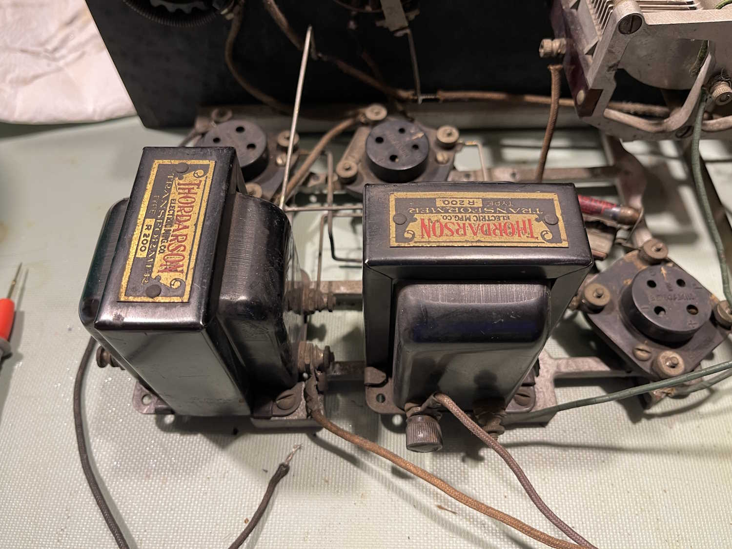
In the last part, we identified where the power connects. This part is about checking coils and transformers to identify any problem areas.
And…there’s a problem. The AF output transformer is open on the side that supplies the plate voltages. This is the leftmost transformer in the image.
While the Thordarson R-200 transformer was a common part for this type of radio, and they are out there in resale land…good examples can go for a bunchabuxx. Bad examples can still be somewhat expensive.
For now, this project stops. I’m not willing to invest a lot of money into what would ultimately be a gee-whiz device. I’ve whittled options down to these:
1: Find a transformer at a show. Perhaps Dayton or Cuyahoga Falls will have one at a reasonable price.
2: Try to open this one up without damaging the crimp ears that keep the mounting plate on the body.
3: Donate it to the Early Television Museum’s operating funds auction in the fall.
I’m thinking #3 is going to be the winner here, as I have plenty of other devices to work on. Stay tuned, this may yet show up in a future post.
When last we met, I had identified where the tubes went, so now it’s time to figure out where the power supplies need to connect. This looked very complex at first, but once I started reading about this type of radio, it became obvious how things were supposed to connect. But first, some other things to take care of.
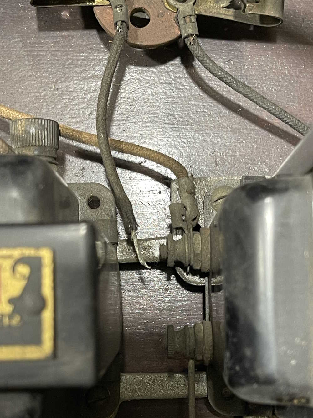
There are a number of broken connections here. The original builder used some very precise bent wires in spots, and made “meh it has to connect” connections in others. Some of those have broken because they were just laid on their connection point without any kind of mechanical connection, and hit with a blob of solder. There’s even some solder blobs in the case indicating repairs were made in situ at times.
The first is the RF amp. This one was just laid on it’s terminal and soldered.
This one was resting against it’s connection point and poorly soldered.
And the final one is just a wire that pulled out of a poorly crimped fork. This one is the 90V supply feed for the final AF amp, and uses the headphones as it’s bias.
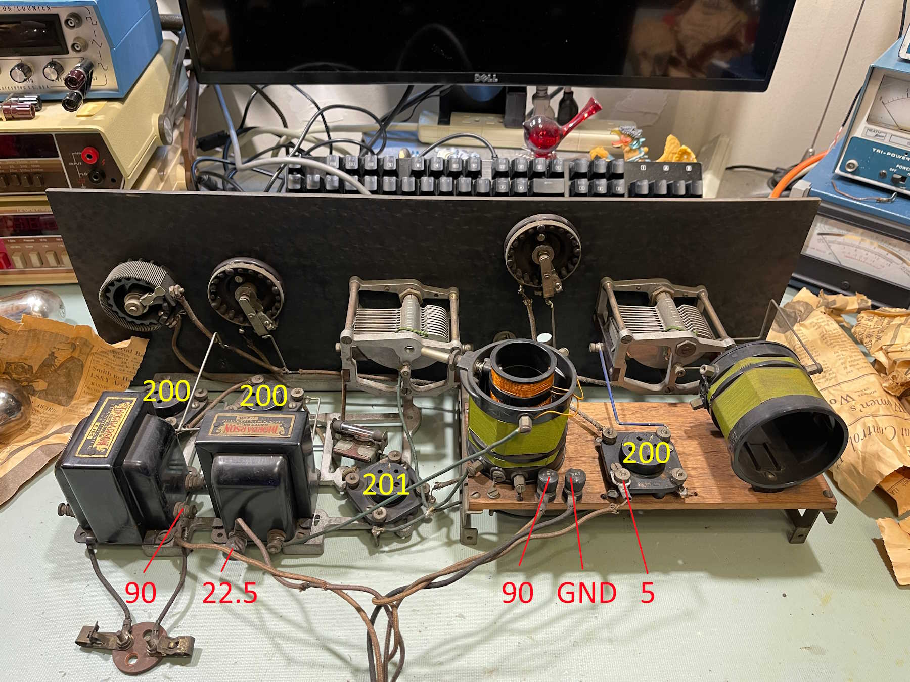
With that out of the way, it’s time to move on to identifying the battery connections. I’ve already identified the tube layout, so it was mostly a matter of tracing back to see where the plate of each tube went. It threw me for a minute that the detector and final AF amps both connection via one of the interstage transformers, but that’s how these were built.
I found it interesting that the unit has two 90V connections, but then it occured to me that the builder was trying to keep RF out of the AF to prevent squealing. If you’ve ever had a radio with a bad AGC capacitor, you know what I mean…
Before applying power, there’s going to need to be some substantial cleanup. All connections are oxidized to the point of insulation - the power switch, for example, doesn’t even read resistance when closed. The tuning gangs are locked up tight, and the battery cables are no longer conductors.
The next step is to check coils and transformers to make sure all are giving a useful reading. Stay tuned!
While not exactly a hamfest, antique radio and electronics goes hand-in-hand with other antiques. This show is the season opener, and has a lot of vendors for that reason and because they want to move things for the holidays. It’s a good “get out of the house” after Thanksgiving, and be sure to get some chocolate-covered chips before you leave!
Scott Antique Market
Ohio Expo Center
717 East 17th Street
Columbus, Ohio 43211
Saturday November 29th: 9AM - 6PM
Sunday November 30th: 10AM - 4PM
Admission to the show is free, but the venue charges a per-car parking fee. See you there!
It wasn’t that long ago that this was wrapped up. (See the bottom of this post for that entry.)
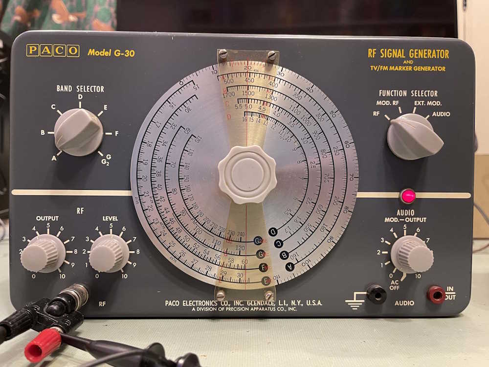
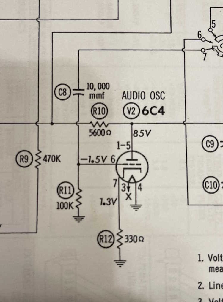
However, a friend pointed out that the schematic didn’t match the unit. In particular, a capacitor in the audio oscillator wasn’t per the information:
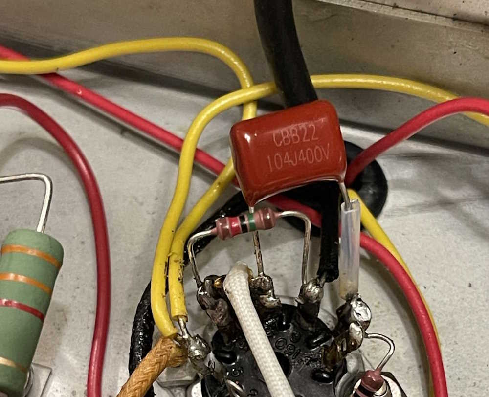
C8 is a 103, aka 0.01μF capacitor, per the schematic. However, what’s in the unit:
That’s very clearly a 104, aka 0.1μF part. Note that the resistor in the image is the one that was incorrect and replaced in a previous post.
No problem, I have plenty of 0.01μF left over from various rebuilds. One goes in easily:
And,
It won’t oscillate. Okay.
The old part goes back in, and all is well. It’s oscillating again, right around the 499Hz it was the last time we looked at this unit.
So, what gives here? Well - I’ve found that many of these devices didn’t exactly follow the manufacturer’s information. Schematics were often printed before the unit was manufactured, and things changed. Problems were corrected, circuits were changed, new variants were released - all kinds of things that make what you have on the bench and what you see on paper deviate. You literally have to expect the unexpected here, or you’ll go crazy trying to figure out what happened.
I assume that the original owner probably put this part in, after discovering the same thing about the oscillator. Regardless, it’s back the way it was and bolted together again, waiting for it’s time to shine.
This was an interesting device that required following a fault back to what was (most likely) it’s original source.
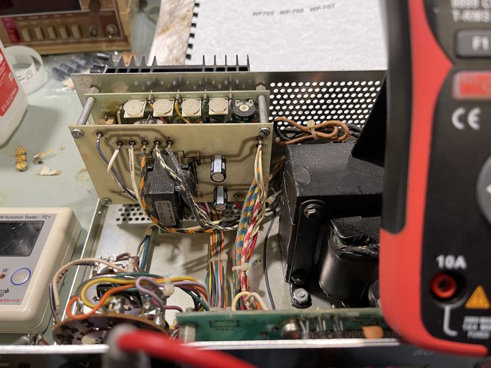
I’m going to assume that the regulator was probably destroyed by the noise spikes coming from the power supply transformer’s broken leads - either the spikes in the voltage caused it, or the excessively low voltage eventually destroyed the device. Who knows, but ultimately, the regulator was bad and the transformer board needed a complete re-solder.
In addition to the regulator board, there were a couple of 4.7μF capacitors on the display board - those were replaced, as were the 470μF capacitors on the display supply. There are larger capacitors on the actual regulator board, and those will need to be replaced as well - but they’re oddball sizes and will take some finding.
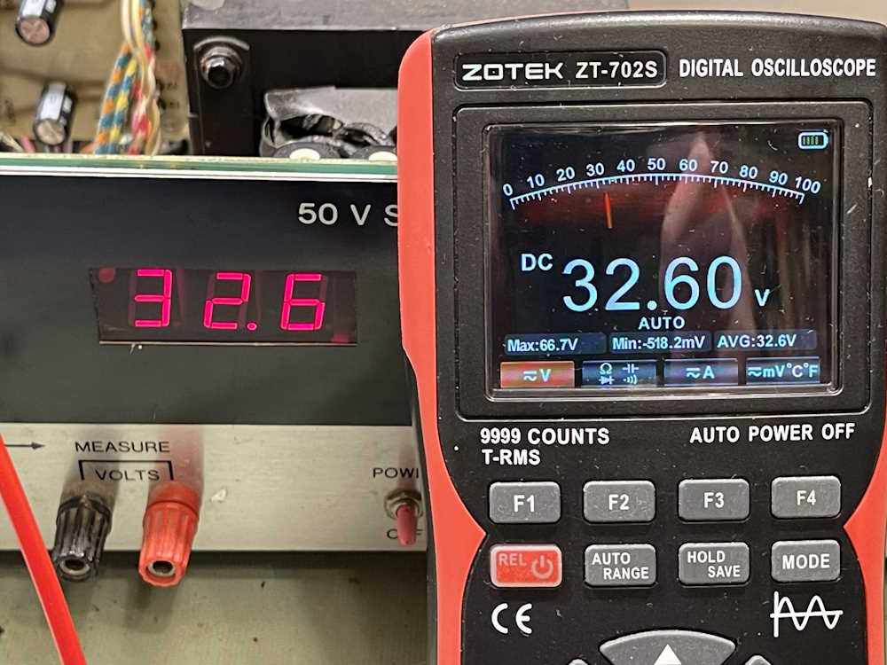
The last thing is to calibrate the display as best I can. While I have a manual, it’s of no use here because it’s for a different rev. I eventually discovered that the potentiometers on the display board calibrate the external measurement, and then the internal measurement. This was just turning them slightly and seeing what happened, and it was easy enough to dial in the correct values.
It was then buttoned up, ready for use. I’m not going to talk more about the calibration, since all of these seem different - but don’t be afraid to turn things just a tiny bit to see what happens, but always be aware of what you could be causing before doing so! Make sure you can fix it if you break it.
The two takeaway points on this were:
The manual you can purchase, while it claims to be the correct one (and mine is indeed for the WP-705) may not be the correct one, especially if the manufacturer assumed lines from another company.
The fault you see up front isn’t always the cause of the problem. In this case, tracing all the way back to the input revealed what probably caused the issue here.
With that, this unit goes on the shelf, waiting for it’s use. I suspect it’s going to see service with a coming project, something where some oddball voltages are needed. Stay tuned!
This is the last hamfest of the season for me. It’s usually pretty good, and this year was no exception - there was a smaller, but still decent amount of things to see. This one is far enough away that I didn’t see the same vendors as the locals.
Here’s what I saw at the show:
An in-the-box ratshack weather radio.
A nice 6L6 amplifier chassis.
A lineup of rapidly vanishing boat anchors.
A nice HO scale Big Boy engine.
I always take at least one book home.
A seldom seen Squeezebox Boom. It went home with me.
An ancient CB full of tubes.
FM is a fad, it will never last.
Cameras for your 35mm needs.
A lovely green plastic radio.
A decent induction plate at a good price.
Trash-80 Model 4. Quite unusual.
Too bad these take unobtanium batteries.
The Magnavox in the back was probably made nearby.
A mid-century lineup.
Equipment and radios.
A neat cloth-covered portable.
A good one for the S38 index.
I bet you never thought you'd see radios!
Some Select-A-Tennas. These aren't mid-century.
The soldering iron and stand went home with me.
Anyone remember those early sound devices?
A very cool, but probably unrepairable Tek rack.
Remember Wang? They made minis and WP systems.
We thought this was a MASCO unit at first.
I always pick up appliance modules when I see them.
.
My fellow show-goer and I are probably going to put this one on a semi-regular basis. The long drive and relatively high admission fee (the venue charges you to park as well) factored into that decision. But, we’ll go if time allows and we feel like it, so there still may be photos next year.
The next show is the Scott Antique Market here in Columbus, at the state fairgrounds / expo center. This one is more of a, well…antique show, but old electrical equipment and antiques are really the same thing. It’s a chance to get out of the house after the holiday and wander around, as well as pick up some chocolate-covered things from the booth that usually appears at the front of the show.
See you there!
(I’ve adjusted the photographic quality a little…if they don’t look good, please let me know on mastodon or LinkedIn.)
This is a show I’ve been attending for some time, and it’s usually pretty decent. Last year was, unfortunately, a lot smaller than normal - probably 2/3 regular size if that. Not sure what was going on there, but I’m waiting to see how this year’s show goes before I make plans to attend in 2026.
This is a completely indoor show at the Allen County War Memorial, a large event center. It occupies one of the large event halls. There’s usually some arena style food on site, if you need that.
Fort Wayne Hamfest
Allen Country War Memorial Coliseum
4000 Parnell Ave
Fort Wayne, IN 46805
November 15 16
Hours vary by day, opens at 9AM
https://www.acarts.com/hfmain.htm
Admission is $10 and the venue itself charges $8 for parking. See you there!
With 2025 coming to a close, I find myself thinking about each show I attended this past year, and which ones I want to go back to. While the first answer is “all of them!” - I think I’m going to cut back some this year. The smaller shows are cool, but I started seeing the same vendors and the same items over and over. This will give things a chance to cycle through.
So - instead of 15 hamfests, I think I’ll probably drop back to 8 or so. There may be a few others in there - Athens, OH and Clearfield, PA, but those will depend primarily on “if I feel like it,” and perhaps Fort Wayne if 2025’s show turns out better than 2024.
As before, not all shows have updated at the time of this posting, so check back or check the Ohio ARRL section page for current event times Links to pictures will be posted as soon as I can after a show, and there will be a year-end wrap-up.
Cuyahoga Falls Amateur Radio Club Hamfest
Emidio & Sons Party Center
48 E. Bath Road
Cuyahoga Falls, OH 44221
Saturday April 11
8A - 1PM
Admission $10
https://sites.google.com/cfarc.org/cfarc/hamfest
Event photos: Coming soon.
Dayton Hamvention
Greene County Fair and Expo Center - The Whole Thing
210 Fairground Road
Xenia, OH 45385
Fri Sat Sun May 15 16 17
Hours vary by day, opens at 9AM
https://hamvention.org
Friday Photos: Coming soon.
Saturday Photos: Coming soon.
Sunday Photos: Coming soon.
Breezeshooters Hamfest
Butler Farm Show
625 Evans City Rd
Butler, PA 16001
Sunday June 14
8A - 2PM
https://breezeshooters.org/ns/
Event photos: Coming soon.
Columbus Hamfest
Aladdin Shrine Center
1801 Gateway Cir
Grove City, OH 43123
Date TBA, usually early August
8A - 1PMish
https://aladdinshrine.org/hamfest/
Event photos: Coming soon.
Johnstown Swapper’s Day
Johnstown Community Sportsmen’s Club
7357 Sportsman Club Rd NW
Johnstown, OH 43031
Labor Day Weekend (Fri Sat Sun)
7A - 6P
https://jcscohio.org/swappers-day/
Event photos: Coming soon.
The Cleveland Hamfest and Computer Show
Cuyahoga County Fairgrounds, Eastland Entrance
160 Eastland Rd
Berea, OH 44107
Sunday September 27
8A - 12P
https://www.hac.org/
Event photos: Coming soon.
Early Television Museum Fall Swap Meet
The Early Television Museum
5396 Franklin St
Hilliard, OH 43026
Date TBA, usually October
10A - 2P
https://www.earlytelevision.org/swapmeet.html
Event photos: Coming soon
Scott Antique Market November
Ohio Expo Center (State Fairgrounds)
717 E 17th Ave
Columbus, OH 43211
Usually Thanksgiving weekend
Hours vary by day, check before you go.
https://www.scottantiquemarket.com/
Event photos: Coming soon
There’s a handful of “Maybe” this year as well. I’ll get to these if time allows:
ACARA Athens Hamfest
Athens Community Center
701 E State Street
Athens, OH 45701
Date TBA, Usually late April
https://www.ac-ara.org/
Central Pennsylvania Hamfest
Clearfield County Fair Grounds, Agriculture Building and grounds
5615 Park St
Clearfield, PA 16830
Sunday September 13
https://clearfieldcountyarc.net/hamfest/
MARC Hamfest
Military Air Preservation Society Hanger (MAPS)
2620 International Parkway
Green, OH 44232
Date TBA, Usually early November
http://w8np.net
Fort Wayne Hamfest
Allen Country War Memorial Coliseum
4000 Parnell Ave
Fort Wayne, IN 46805
Date TBA, usually right before Thanksgiving weekend
https://www.acarts.com/hfmain.htm
Johnstown Swappers Day and the Scott Antique Market aren’t really hamfests, but enough electrical and other goodies show up that it’s worth going if you’re in to general flea market type items. The Early Television Museum is a swap meet that happens during one of the venue’s open work days, so who knows what will show up there.
Always check dates and times before you go, and I’ll see you there!
This show, held at the MAPS facility in North Canton, Ohio, seems to have “the stuff we want” - piles of radios, tables of things, and generally a good selection set up the way you remember shows being. This year was no different, and - while the show itself is of moderate size, they sold out every table. The museum exhibits that you can view while at the show are kind of cool, too.
I didn’t pick up much at this show, some parts and a book, but there were a lot of things I would have liked to have. They have to stay where they are, however - I have enough projects for now!
This is what I saw at the show:
A couple of clock radios. I bet they go “clunkclunkclunk.”
A massively overdesigned decade box.
A giant EICO generator.
Random equipment for sale.
An early Leader signal generator.
A selection of vintage meters. Got any 22.5V batteries?
A morse code sender/receiver setup.
It's good for a project. Only $5!
Some consumer table radios.
Odds and ends radios.
This is the stuff we come to look at.
More odds and ends.
A little travel radio-clock.
The show.
Parts from an old TRF radio.
Calling the (retro) future!
.
This is the second-to-last show I’ll attend this year, not counting the local antique shows. Next and last is Fort Wayne, which happens the weekend of the 15th and 16th of November. See you there!


 future!")