I have to fix the equipment before I fix the equipment.
Saturday, December 9, 2023 at 15:09:47
Earlier this year, I went to the Cuyahoga Falls hamfest and brought home a Regency EC-175 frequency counter. This device has a OCXO in order to maintain a low PPM deviation for FCC compliance use. It’s really kind of an odd piece for Regency, and was going for next to nothing.
https://wereboar.com … yahoga-falls-hamfest
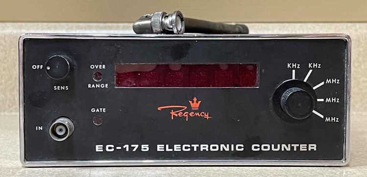
The Regency counter works, but is off by a considerable margin. I suspect this is probably just the 10MHz oven needing some adjustment.
My plan was to poke around inside of it and determine what was what, as I don’t have a service or operators manual. (I’ve since found an operators manual and will post it as soon as possible.) I was planning on using a cheap Lodestar signal generator and my Fluke 1910A 125MHz frequency counter to try and bring the Regency into adjustment.
So I set up, and…the Fluke counter doesn’t work. It will work as an up-counter, but won’t count frequency input. Hitting the “CHK” button, I get nothing:
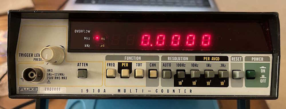
This should be showing me the internal 10MHz clock. I play with various things and get nothing.
Time to open it up.
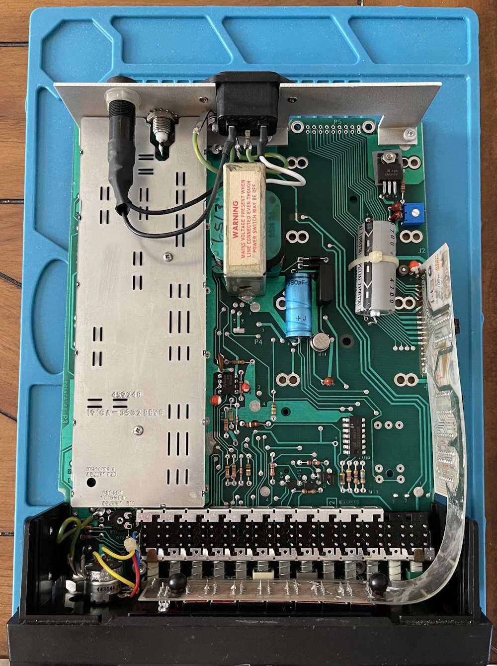
Nothing looks burnt. The section I need is underneath the RF cover, so off it comes. The parts in question, according to the schematic, are at the back of the unit near the metal backplate.

But before we get into those parts, a quick power supply check is in order. There are two voltages, +5 and -12.
+5 = 5.02
-12 = -11.80
The -12V is a TO-5 can device, and is pretty warm. I’m not sure if that’s supposed to be like that, but since -12 isn’t in the oscillator circuit, I’m going to ignore it for now. The logic supply of +5 is fine, however, so we’re good there.
The parts I’m going to be interested in here are :
U5
Q7 (under the heat-shrunk connector in the foreground)
Q8
Y1
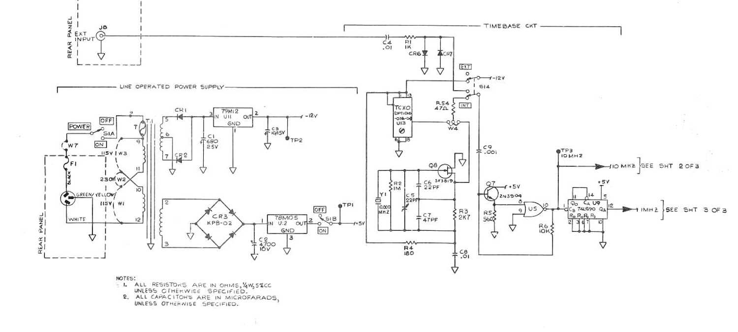
I’m not really worried about U9 here because if I don’t have any 10MHz, I’m not goign to have any 1MHz. U9 is a divide by 10, so we’ll worry about that when and if 10MHz is available.
U5 pin 10 should be 10MHz. There’s nothing, so move back.
Q7 Base should be 10MHz. There’s nothing there, either.
I’m now going to switch the counter to EXT mode, as to remove those two parts from the circuit.
Q8 is an interesting part here. It’s a JFET, and the schematic appears to show a 2N3819. (It actually looks like SN3819, which isn’t a valid number.) However, that’s not what’s in the unit. I have a J310 VHF JFET which has a different pinout.

Always be careful, sometimes manuals you find online contain older or newer revisions of the device you’re using!
This confused me at first, because I was trying to test it like a 2N3819 and was getting a short on Gate to Drain, Pin 2 to 1. What I was actually reading was Drain to Source, which should be a somewhat low resistance. In this case, I had 37 ohms. That’s probably fine for a JFET, since Drain and Source are mostly the same slab of silicon. Without pulling this guy out and testing in an active tester, I assume it’s good.
No capacitors appear to be shorted. The few resistors in the circuit are fine for what they are, and are well within tolerance.
That just leaves the crystal. I don’t really have any way of testing it. I can try capacitance, but the resistors in the circuit will ruin that low pF measurement, so the only way is to pull it out.
The conclusion is the oscillator isn’t. The assumption here is the crystal is bad. Maybe cracked or internally damaged from time or handing? I don’t know - I’m going to try and obtain something similar to swap in and see if it works. There’s also a possibility I could find a cheap TXCO or OXCO to put in the area where Fluke would have mounted a TXCO, which should provide a better device.
That assumes the device is operational up front. These aren’t known for being reliable as they age, perhaps I’m just wasting my time with this. But I know where the problem lies, so there’s no harm in getting a few dollars in parts to try and make it work again.