An Eico 145 Signal Tracer - Part 1
Sunday, March 24, 2024 at 20:10:06
( Read the first part of this series here: https://wereboar.com … ignal-tracer-part-0/ )
I’ve decided to give this Eico 145 tracer a new lease on life and put it into service on my test bench - but to do so will require replacing the bad parts. Which ones? Pretty much all of the passives aren’t any good at this point. The device itself isn’t the cleanest example of it’s kind, with lots of battle scars. Paint and rust decorate the front panel and chassis, and input jacks have been added to the front.
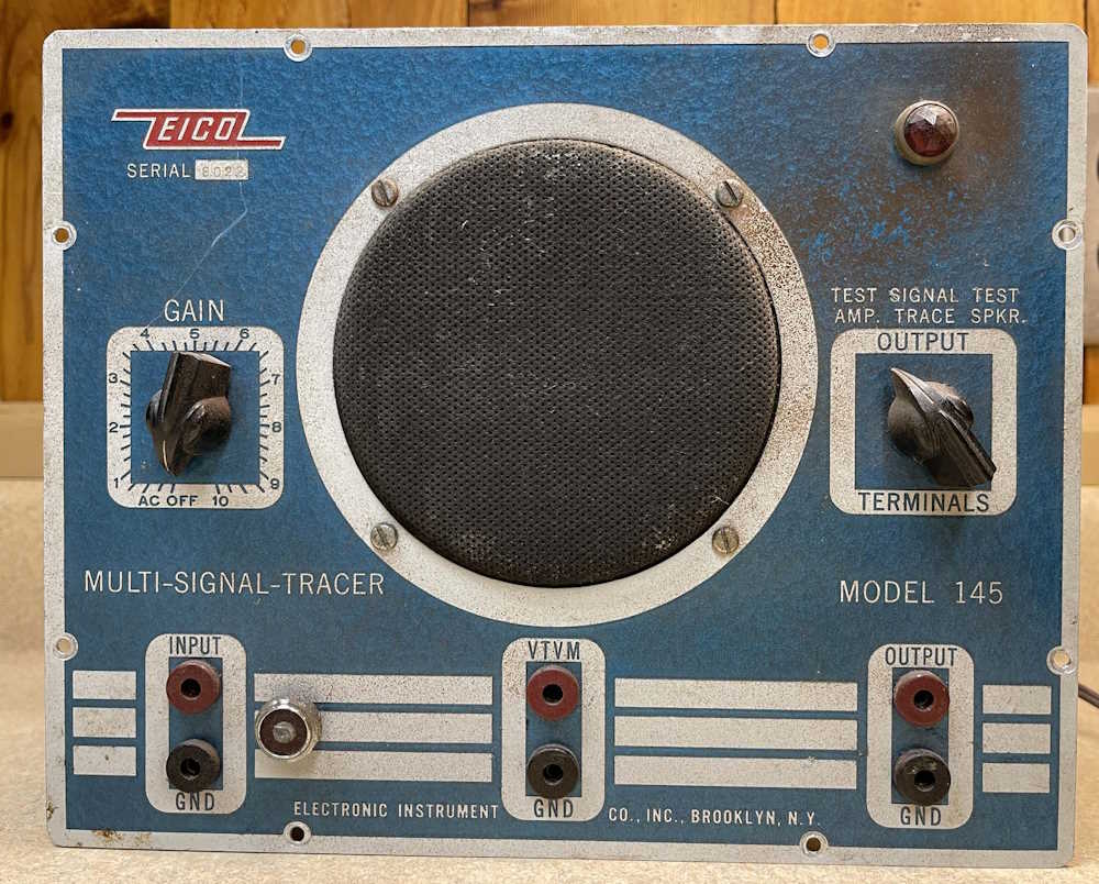

The signs of use are the reasons I’m putting this on the bench. It’s already seen it’s share of use and won’t mind some more.
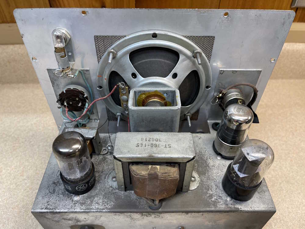
The chassis has the expected rust and age. That happens, there are no rust outs or severe damage here so I’m not worried about it.
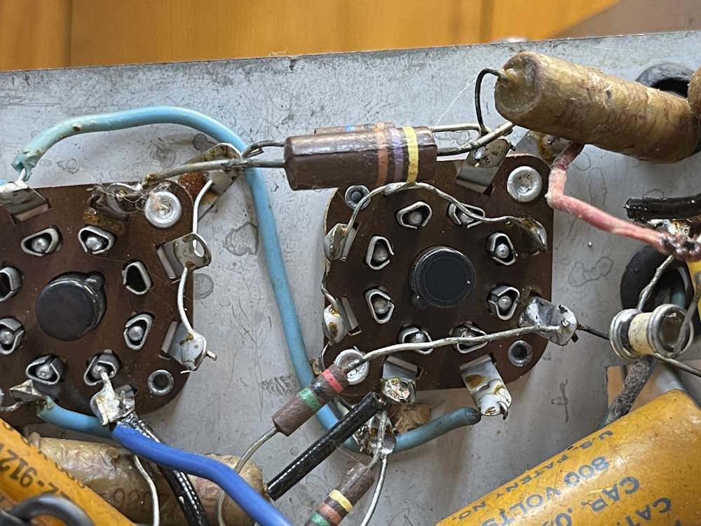
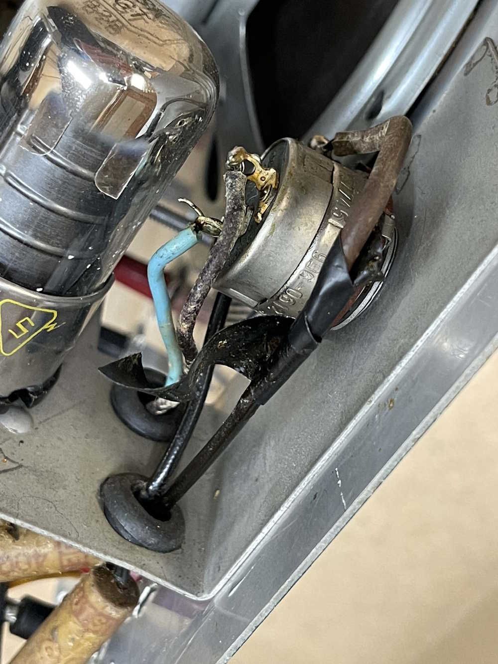
The unit itself has some interesting things about it. There’s supposed to be a 10uF capacitor across this big 470Ω resistor. This is the cathode resistor for the audio output tube, and the capacitor is there to improve audio fidelity. I’m not sure if that was omitted because it’s not going to do much when most of your signal is 1Khz, or if it was damaged and removed at some point. The capacitor visible at the bottom is also an oddity, being an 800V part on the grid of a 6SJ7 - there’s nowhere near 800V present in this unit, and nowhere near B+ on this grid. Why this is such a high voltage part is a mystery but is probably just “That’s what I had on hand.”
The audio output transformer is somewhat of a mystery as well. I can’t tell if it’s been replaced or was just misdrilled. It doesn’t match the holes in the chassis, so I need to track down the part number and see what it was originally meant for.
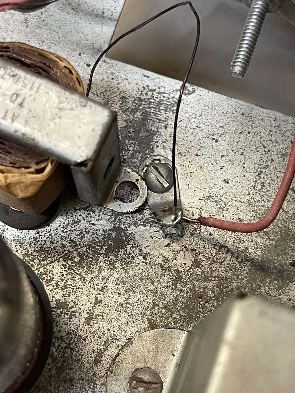
Tape and wire and WTF indicate this thing had multiple repairs over the years. All of that needs to go.
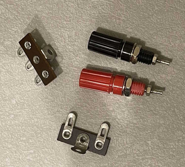
Some more user friendly parts will be added to clean up the device and make it more accessible.
There are some other considerations to take into account. This device was originally meant to be ran on 110VAC - unlike our modern line voltages of 120 to 125VAC. This means B+ is hot, and filament voltage is well over 7VAC - in this case I measured 7.11VAC! That’s too hot, and will burn out the tubes in short order. Another restoration suggested a couple of parallel opposing diodes to drop the voltage in the filament line down, so there will probably be a couple 100V 2A diodes in this thing’s future. It was also suggested that the 6K6 is being run hot, so increasing the cathode resistor’s value (the large 470) would bring the power on the plate of this tube down.
Since most of the parts are being replaced, the analysis is just to make sure there aren’t any major problems that would stop the show - and I don’t see any. The next step is to create a new parts list from the schematic and get things ordered.
I’ll see you in part two with that schematic and a parts list.
Next part of this series: https://wereboar.com … ignal-tracer-part-2/
Previous part of this series: https://wereboar.com … ignal-tracer-part-0/
Wrapup and link to all posts: https://wereboar.com … -and-final-thoughts/