The Heatkit AF-1 Analog Frequency Meter, Part 7 - Rebuilding the filter.
Tuesday, March 25, 2025 at 07:35:11
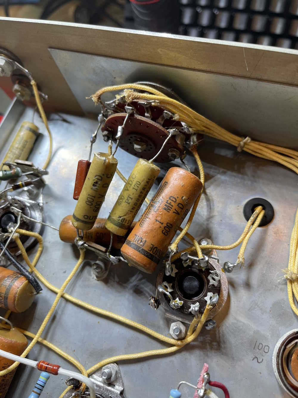
Before doing any testing, I wanted to rebuild the filter section of the unit - if the parts in this area are leaky, then nothing is going to work properly. I’m not as concerned with the rest of the circuit - that’s because if it’s repeatable, then I don’t care what it’s doing as long as it does it every time. This may be a bad assumption, but since it’s going to get rebuilt at some point there’s no need to worry about it now.
I started by identifying what needs to be replaced. That amounts to 4 capacitors, and one resistor (hidden on the switch.) There’s another capacitor underneath the four I need to replace, since it’s in the way it will get replaced at the same time even though it’s not part of this circuit.
They took a little bit of doing to get out because I didn’t want to cut things - I’d like to keep these for leakage and other testing as to verify my equipment is working. “Calibration standards,” so to speak.
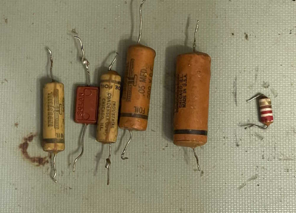
I did some basic testing on these with the equipment at hand. They all register fine at low voltages, mostly close to their expected tolerance ranges of +/- 20 or so percent. Even the resistor was good at 221.5Ω. No leakage tests were performed, nor were any frequency tests performed. Vloss was quite good for old parts, however.
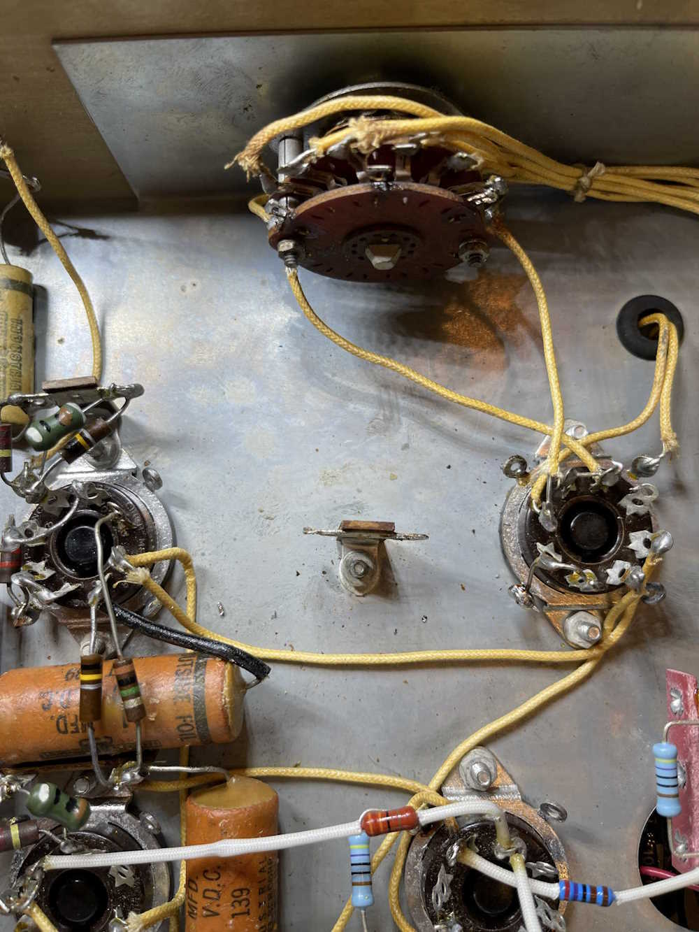
The area was cleaned and prepped for new parts:
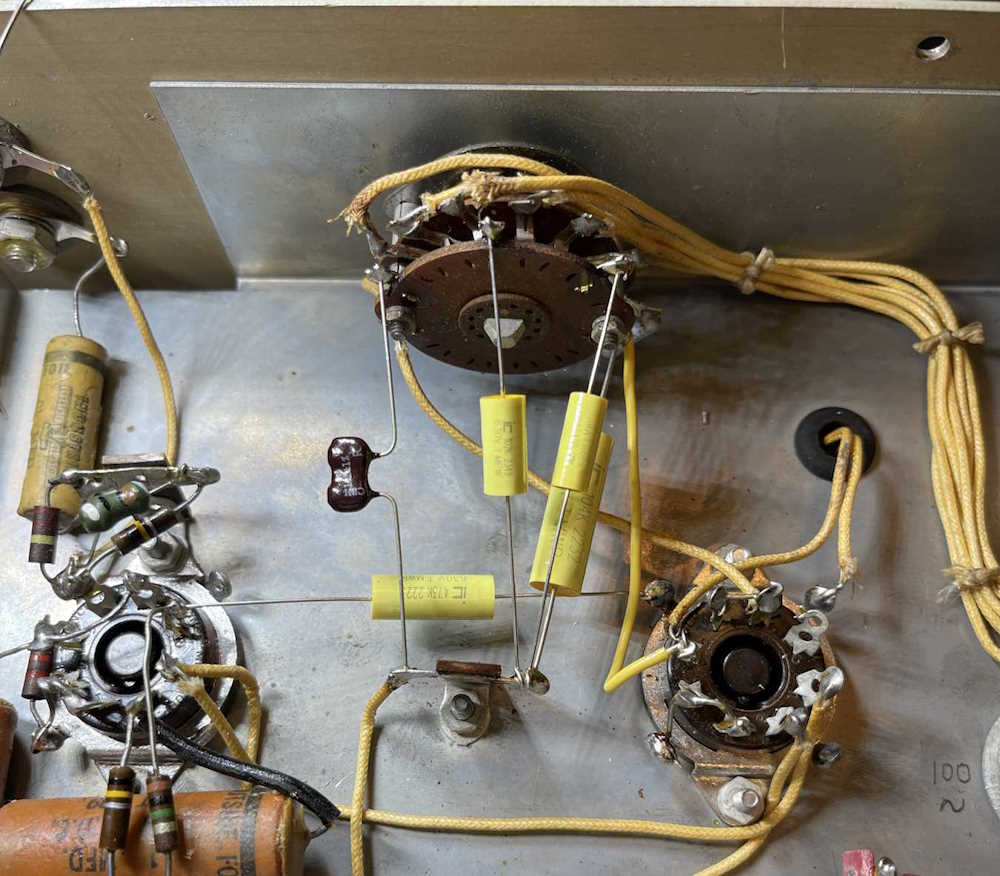
For this rebuild, I chose my go-to IC film capacitors rated at 630V. The max voltage in this unit is around 235VDC, so 400V units could have been used - but I’ve tried to stay as true to the original as possible. The only similar-for-similar replacement was the mica part on the end.
The new parts are significantly smaller than the old ones, and look nice in their new homes:
With the replacement of a damaged piece of wire and a quick check of my work, it’s time to move on to the potentiometers, which will be used in this round of testing.
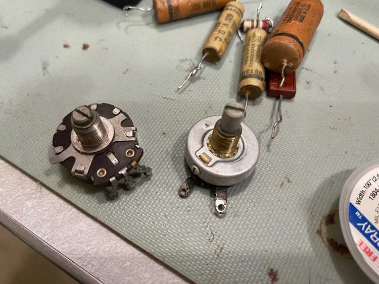
Now that the problem preventing testing has been cleaned up and the business end of the unit has been rebuilt, I went ahead and put two new potentiometers in the unit. Both are 10-turn wirewound 2W units. 200Ω for the 100Hz band and 5kΩ for the 300Hz band - as was in the unit when I received it.
The schematic states that there should be 200Ω in all positions, so I’m not sure what’s going on here.
I’ve removed the old parts. These will go into the parts bin.
And new ones are installed:
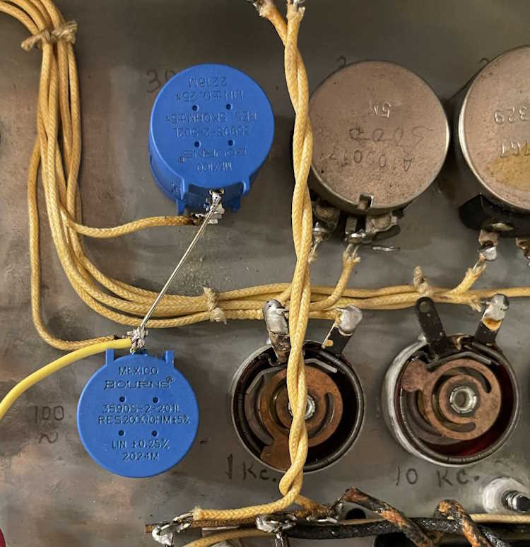
(No, these aren’t Bourns pots…the manufacturer stole the logo, of course.)
100Hz dialed in as expected as was decently linear across the band. 300Hz, however, ran the pot all the way out and could have probably used another 1K of resistance.
I’m not sure what’s going on with that, but I do know there are several more leaky parts in here. Since I’m planning on replacing all of them anyway, I’m going to go ahead and do that before poking at this with a scope. Stay tuned!
Next part of this series: https://wereboar.com … ding-the-rest-of-it/
Previous part of this series: https://wereboar.com … ng-the-power-supply/
Wrapup and link to all posts: https://wereboar.com … -and-final-thoughts/