I’m starting to think the only thing this device needs is a good cleaning and calibration. However, there are some electrolytics in this device, as well as one of those 1600VDC blocking capacitors. While those don’t appear to be bad, I’m going to replace them regardless just so this thing is ready for the ages.
As I don’t have a whole lot of low-voltage equipment, I had to order some of the larger part. I also had to order some of the 1600VDC part, since I only buy those as needed. Those are on the way, and we’ll get to those later.
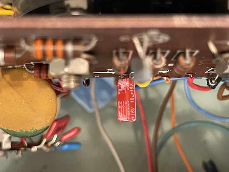
The first part we’re going to replace is the little 10μF 16VDC part that’s in the zero circuit. Surprisingly, it’s not actually bad - it’s just way off of course, like all old electrolytics are. >20μF at about 11Ω - that’s about normal for this small of a part.
But here’s the new one anyway:
I did a bit of tweaking on the calibration adjustments, and I can say I was pleased by what I saw. I believe that was more the cleaning than the capacitor.
As soon as I get the other parts, Ill replace those as well. Stay tuned!
Some time ago, an EICO 242 VTOM came across the bench. While I wasn’t going to do anything with it, I decided to see if I could bring it back to life.
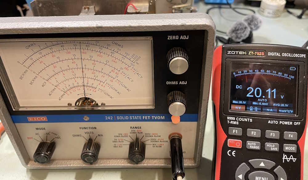
Here’s the issue:
The DVM is measuring 20VDC, the EICO 242 is measuring the same voltage, but reporting only ~17VDC. Something is wrong here.
It’s probably one or more of the following:
Out of calibration
Resistors out of tolerance
Switches are very dirty
Some unseen damage
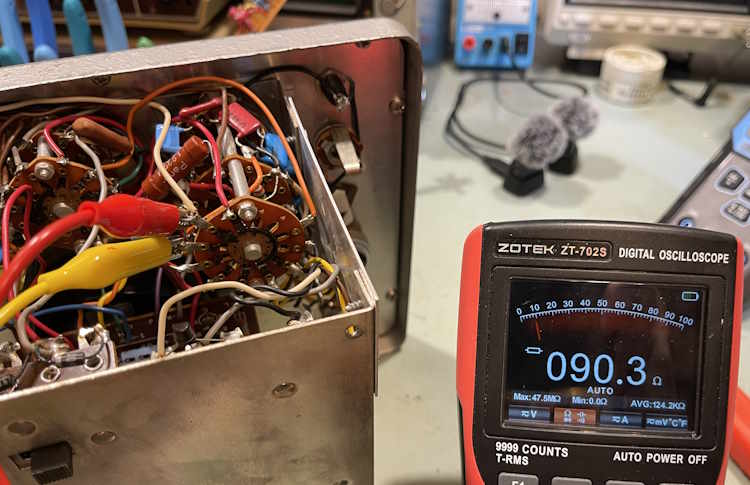
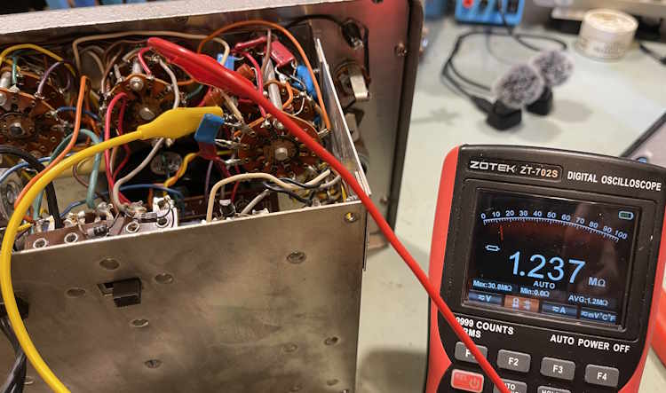
There’s not a whole lot in this device. Let’s check a few resistors:
The first one is supposed to be 90Ω, the second 1.227MΩ. They’re actually pretty good.
I did about half a dozen, and all were like this - quite well in tolerance. Hmm…
The switches are really blackened from age, so I’m going to give them a cleaning and then do a calibration. We’ll see what that does for us. If it gets the meter “good enough!” I may leave it at that…but I’d still like to go through the resistors just to see what’s what, and there are a few small electrolytics in there that certainly need replaced. Stay tuned!
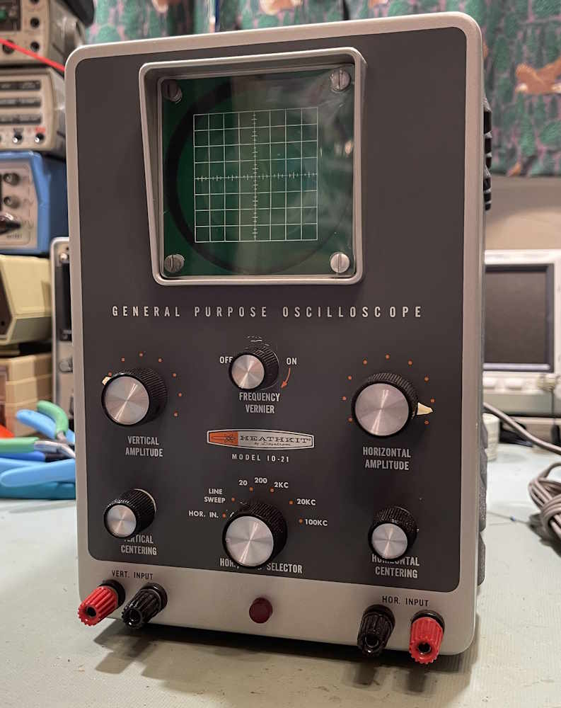
Some time ago, I picked up a moderate condition Heathkit IO-21 Oscilloscope. I was planning on doing some work to it, but in-between then and now, I was able to find a much better unit.
Other than a few minor dings, it’s in great shape.
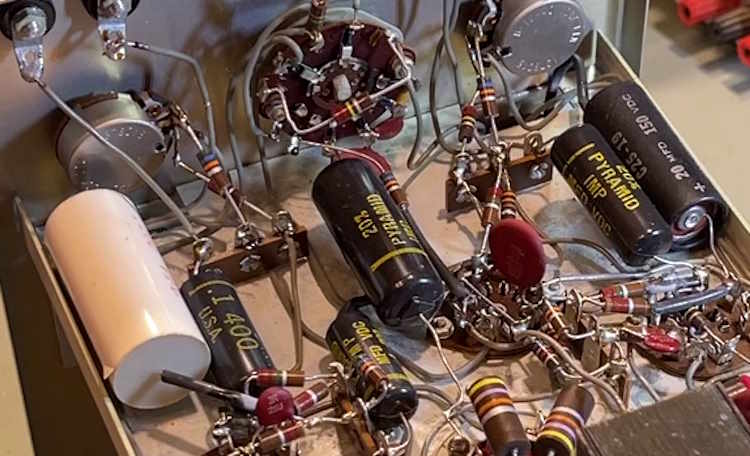
Of course, it’s full of old capacitors. While these seemed to be ok-ish, the ones in the HV circuit were not.
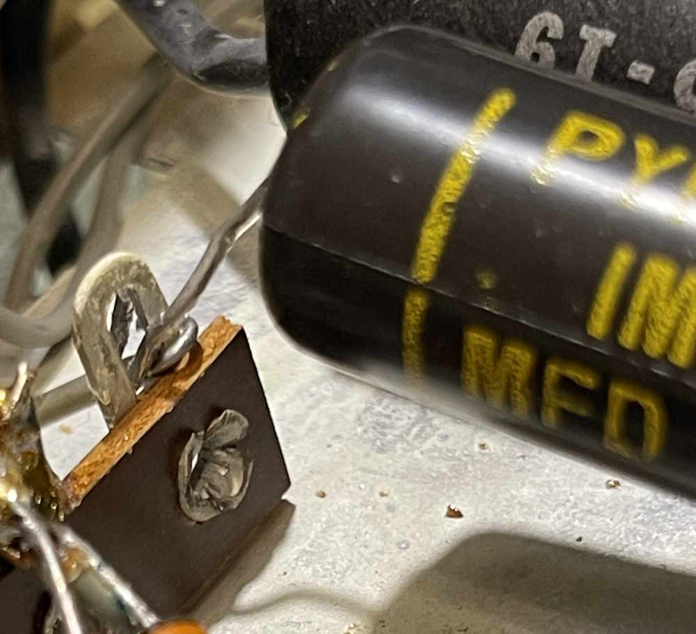
Including this one that wasn’t soldered. I wonder how many problems this caused for the original builder.
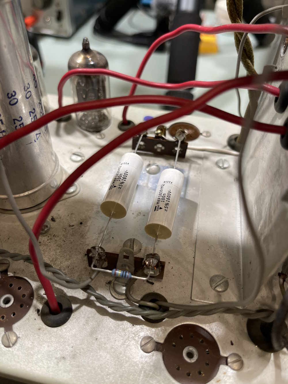
First thing to do is install the new HV capacitors. That’s easy enough, they’re right on top, and the resistor that connects them gets replaced as well in this build.
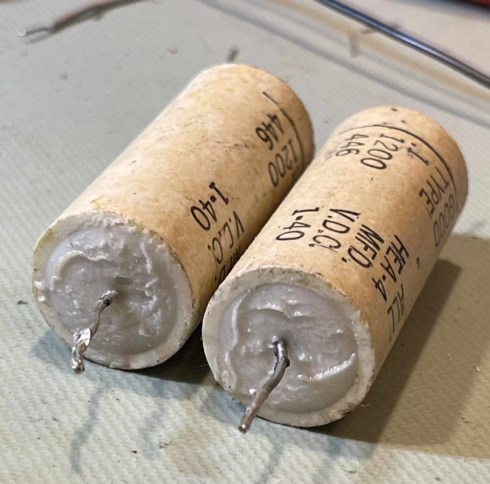
These were old ceramic encased…somethings.
I’m not sure what type these are, but this stuff is gooey wet.
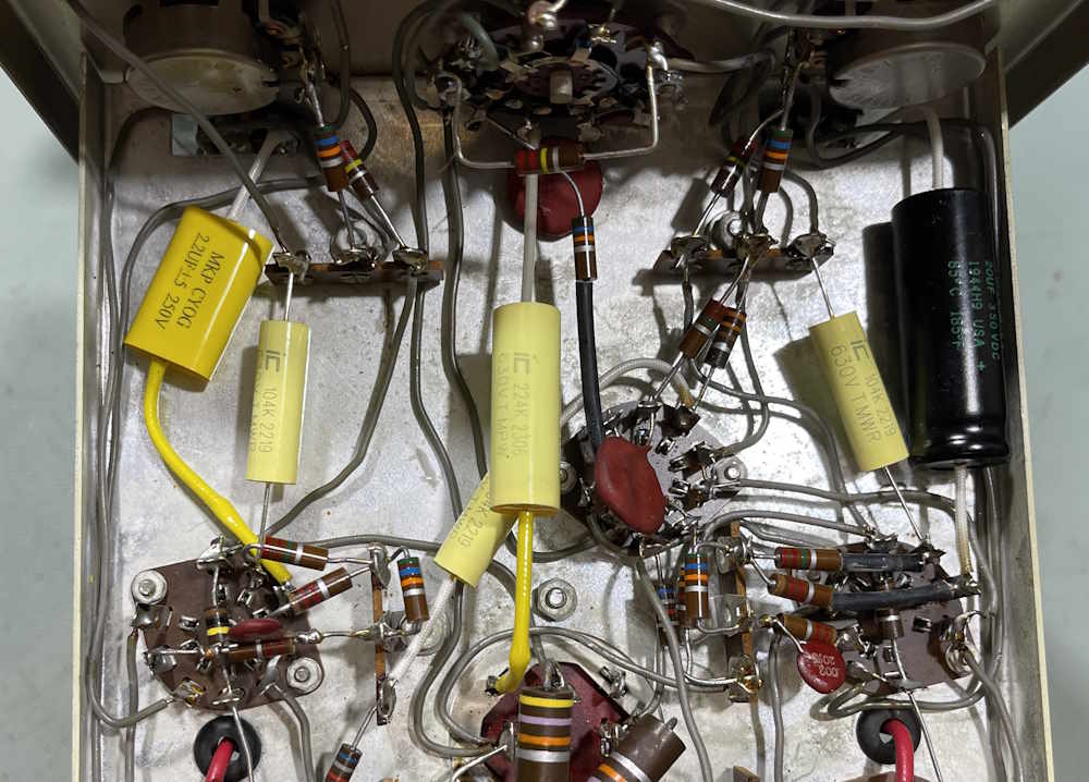
Many of the capacitors in this unit were ceramic disc, and they’re fine…for now. The rest were encased paper, so get replaced with new films, and a new electrolytic where appropriate.
The main filter didn’t seem to be in that bad of condition. A little tired, but not bad. I’m going to leave it alone for now.
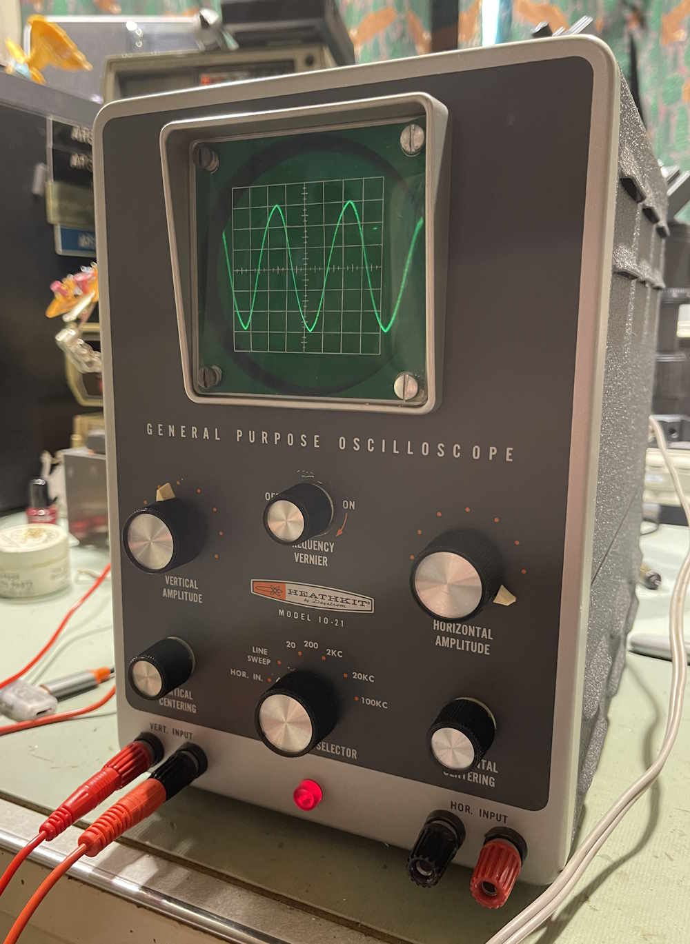
So…does it work?
Sure does.
It works pretty good, and is about what I would expect for a scope this age. I’m pleased with the result, and I now have a vacuum input scope for the bench.
Capacitors
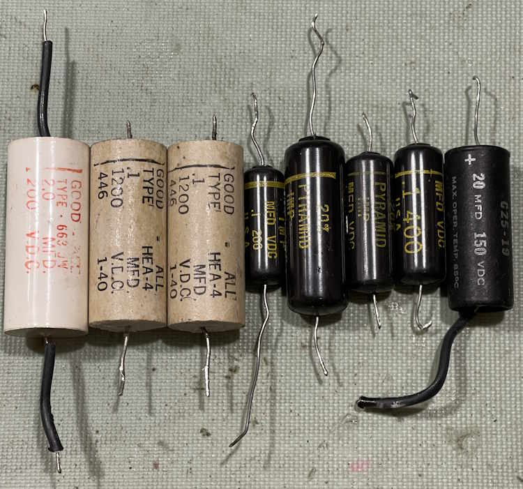
So, what was removed from this thing?
None of these tested bad, but they’re probably bad in the leakage department. I would suspect that the HV caps, with their leaking liquid, are probably not long for this world if you were to use them for any length of time.
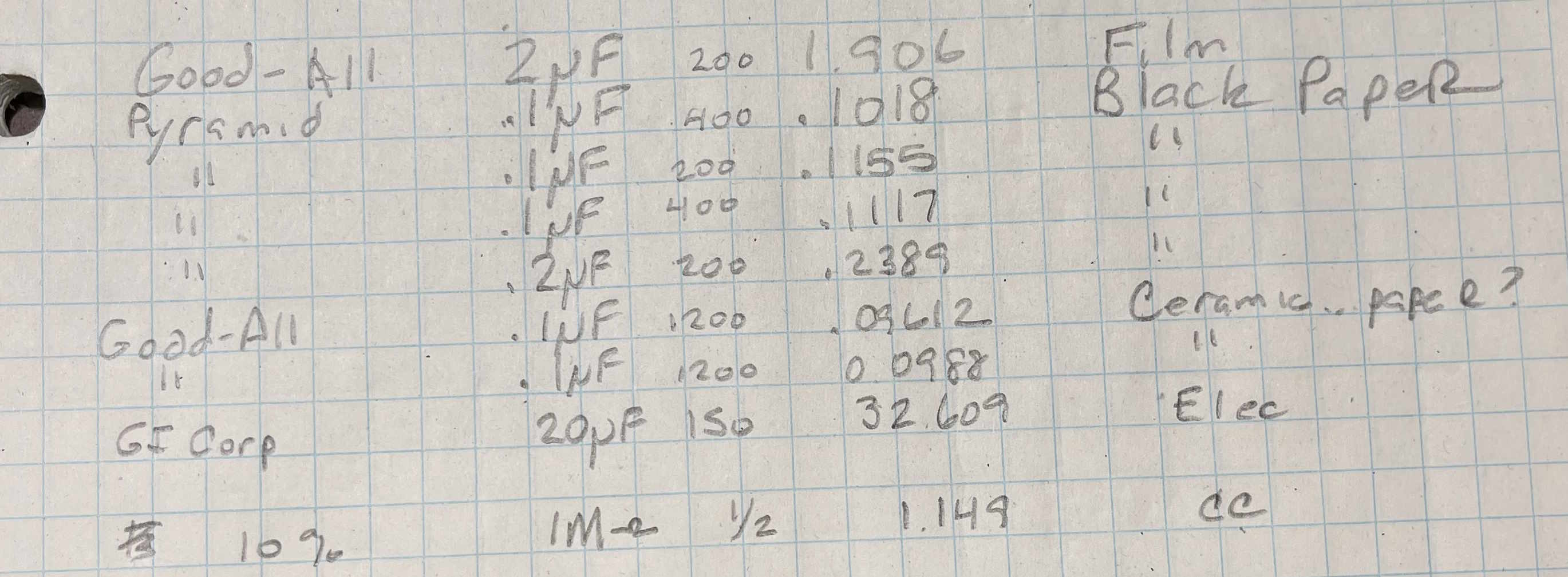
I did a quick check on what each one read, it’s about what you’d expect:
As far as I’m concerned, this device is finished.
Wrapup
This one only needed a little bit of work, so it doesn’t get an entire series. I will probably do the filter at some point, but not now.
In all, the only two surprises waiting here was the no-solder, and the gooey HV caps. Not sure what’s going on here. I did take the time to clean the controls and give the switch a coating of cleaner, for good measure. Everything seems to be working, and no other issues presented themselves.
I have two other examples of this unit - I’ll probably keep one, and sell the other one off for whatever I can get from it. If you’re interested in one of these and you live in the Columbus-Pittsburgh corridor, let me know on Mastodon!The other unit was in bad shape, and had a broken switch, a CRT with a loose plug, and mods that made it a poor example. It is now parts.
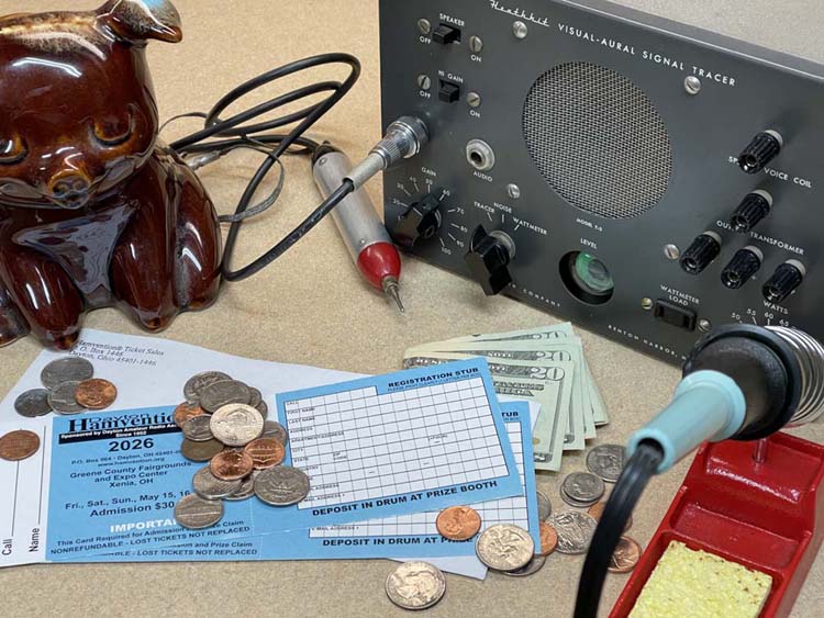
The Dayton Hamvention has decided to do away with paper tickets this year.
I understand that this is just progression, and stopping use of a delivery system that can’t get a parcel to the state next door without accidentally routing it 1000 miles away (yes that’s happened to me recently…twice!) is probably a good thing…
Still.
No more stashing my ticket in a device I bought and repaired, only to find it years later. The paper ticket was the annual introduction to summer for some of us, and a QR code on your phone just doesn’t have the same effect. I guess if there’s anyone that should understand that things have passed us old-timers by, it’s me. Someone whose bench is mostly vacuum equipment.
There’s also the question of how QR code scanning will work. When people enter the show at opening, it’s a long, long line. We hold up our ticket, the people at the gate make sure you have it out, and we move on. Each of these codes will require that the holder stop, allow the code to be scanned (and hopefully your phone isn’t reflecting the scan away,) and then you can enter. This takes a lot longer than just flashing a ticket. I guess we’ll see how bad this turns out - hopefully we won’t have a repeat of the first year at Xenia where traffic was just a mess…
You can order a ticket online at any time, even while standing in line for the show. They’re using some system called fairs dot com, which desperately wants you to allow it to send “updates” (read: advertising garbage) via text. You don’t need to check those boxes when you order, FYI. As always, you can get a ticket here: https://hamvention.org/purchase-tickets/
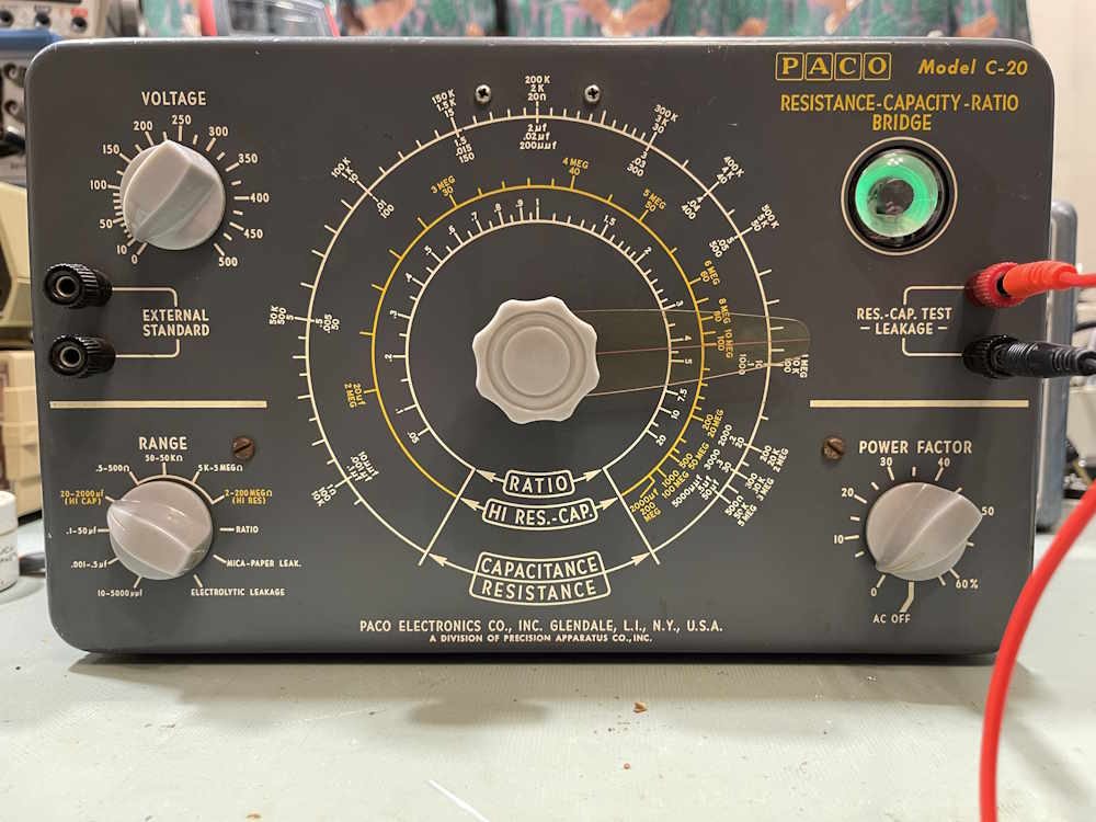
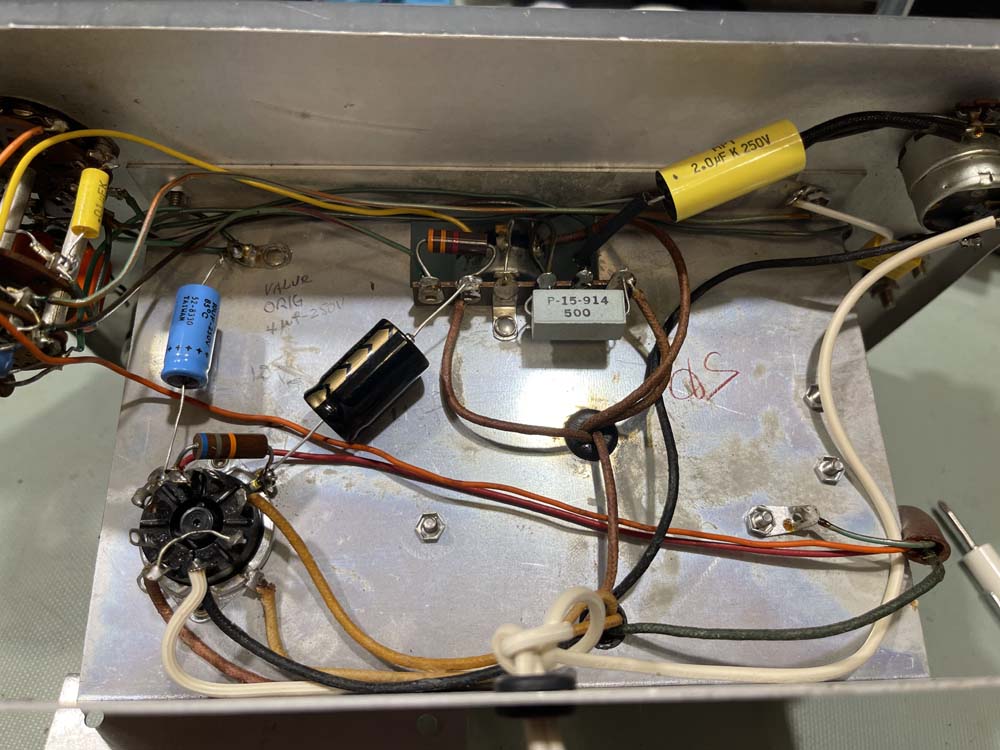
I picked this bridge up at the Columbus Hamfest in August 2026. It’s fully operational, but I wasn’t thrilled with some of the work done to the unit.
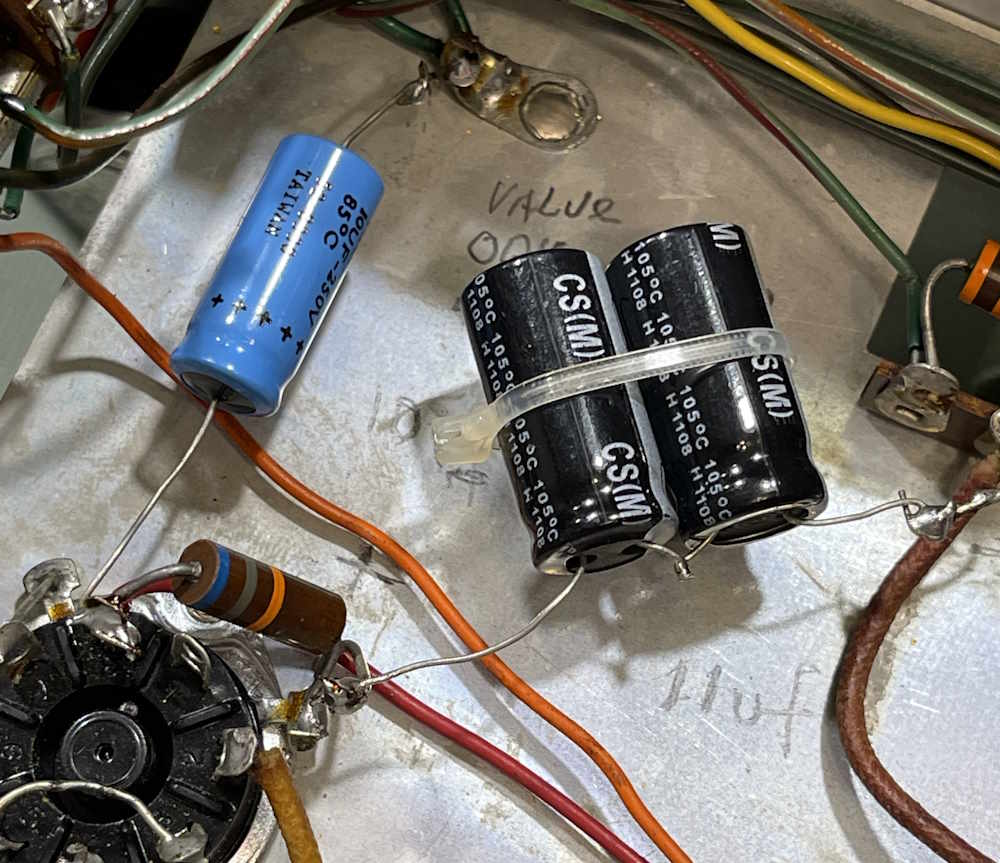
In particular, the wrong type of capacitor was used for the across the line capacitor, and I didn’t like the way the filters were laid in. It also needs a new power cord.
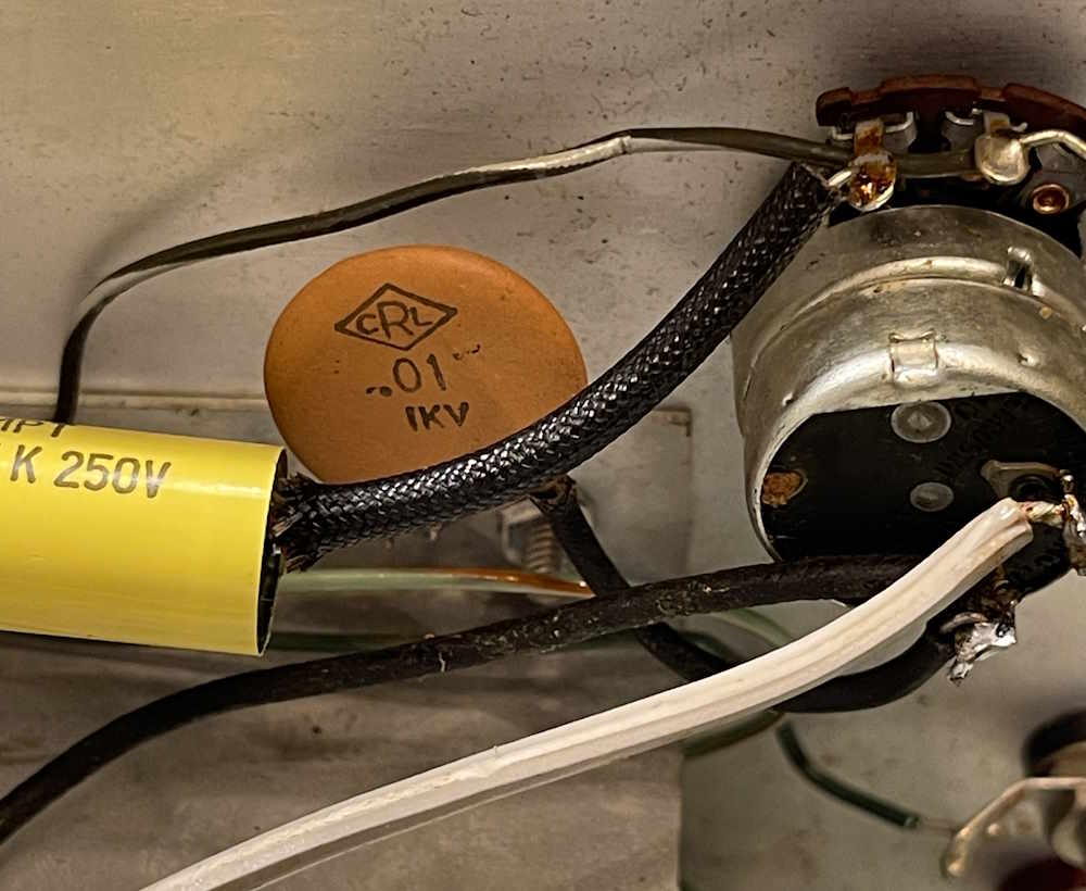
The ACL capacitor is there because most don’t have the correct part laying around in stock. These are essential if you’re going to be working on this kind of equipment, get a few and put them in your parts bin. The filter capacitors are they way they are because the person probably didn’t have the correct voltage part, so he made one by putting two in series. That, of course, has the same effect on capacitance that resistors in parallel has, but it adds the working voltage together. It’s not the best way to do this, but it works and will continue working as long as you’ve sized parts properly and tried to keep some sort of balance.
I was originally going to replace the other filter as well, but it’s fine, and is properly rated even if it’s a higher value capacitance. It’s not going to hurt anything, and it’s likely the original part probably wasn’t anywhere near the actual value printed on the shell. That’s just the way older electrolytics worked - they were plus whatever minus something in value.
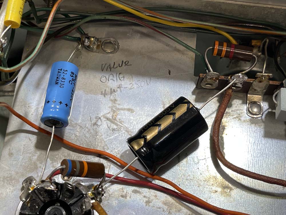
Let’s start with the electrolytic. Here’s a nice new 10μF @ 600VDC laid in. The original was 8μF @ 600, so this one is fine and won’t cause issues.
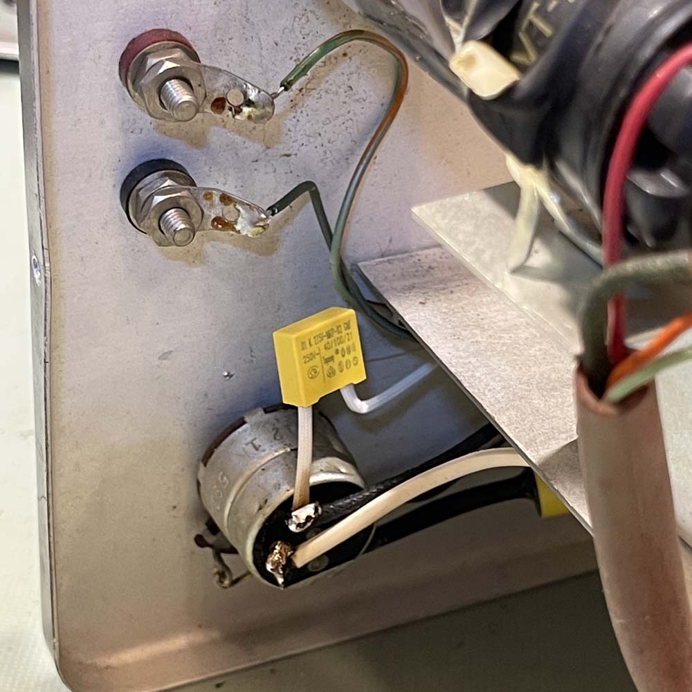
The ACL capacitor is similarly replaced with the correct type of part, and coated with ‘lectric sketti for safety.
And, of course, a new power cord is routed through the chassis, tied with an underwriter’s knot.
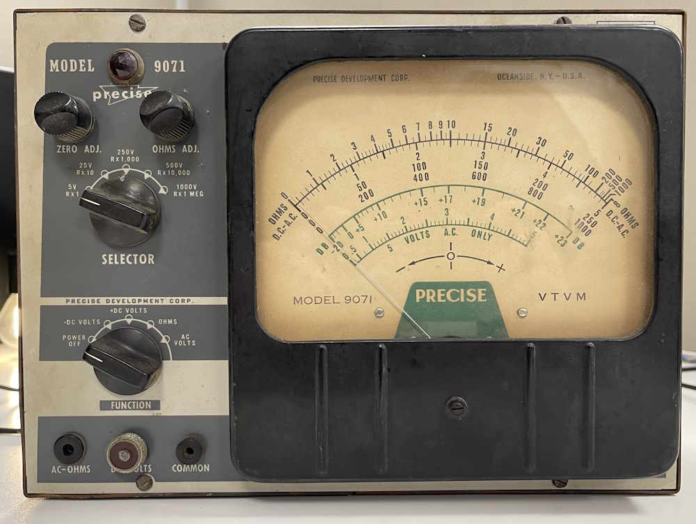
This unit was purchased alongside the unit shown in the first part of the series because, at first glance, it appeared to be in somewhat worse condition than the other device and had the potential to be a donor in case something was wrong.
The face on this one is somewhat different, with the legend being areas where paint is not, instead of the other way around.
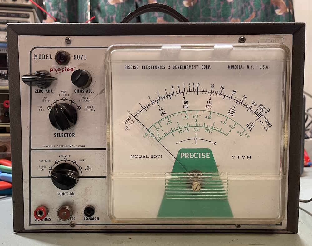
This one has all the correct knobs and input jacks, unlike the other unit. The face is also free of scratches, and has a nice black-framed meter instead of the later, clear meter the other unit has.
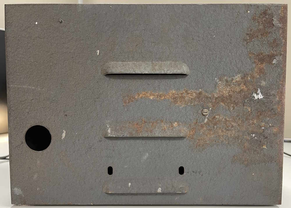
The back shows some scars, however. Lots of rust.
Since the whole side isn’t rot, I assume it just received some damage at some point and then sat in a wet environment.
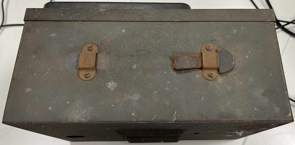
The top is similarly rusty, and is missing it’s handle. Well…there was a small piece of leather left, but that’s it.
Of note here is the cabinet is not the same as the other one. This unit has a simple rim that creates a dish the face sits in, not a rolled out area like the other one.
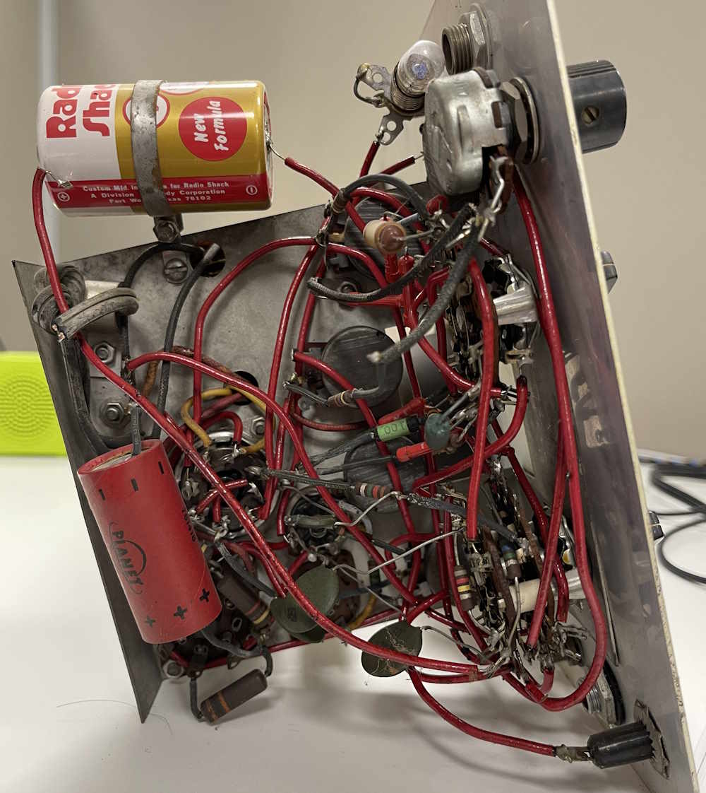
Inside, we have the same rat’s nest as the other unit, with the same amount of ‘lectric sketti. That must have been provided by Precise, as these were sold as kits. Some of it is good, some of it is quite nasty and sticky.
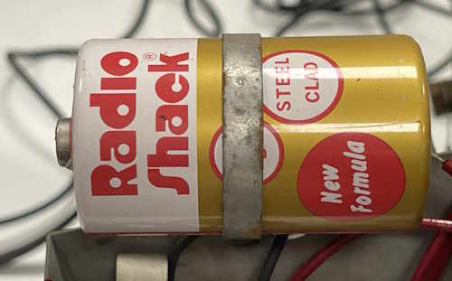
Instead of an old RCA battery, this one has a lovely early 70s vintage Radio Shack battery. Probably dates the last use of this device to the mid 1970s, and it was probably replaced with a FET or early digital unit, assuming the owner had use of a meter.
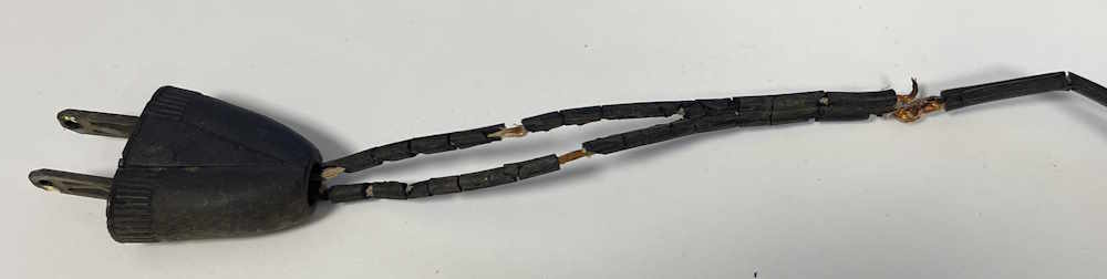
The cordset was in excellent condition, of course:
It was removed and stored in the trash can.
Jay Hooks makes his appearance in this unit as well, so this may have been something needed because of the lead length. But those old blue carbon film resistors aren’t present, this one has slender red ones instead.
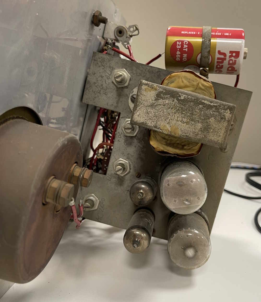
The tube side is the same as the other unit. The meter body itself is quite rusty, so this thing sat in someone’s damp basement for years.
Of note is the filament burnoff on the 6X5, just like the other unit. Either these are hard on that tube, or they were just on all the time. Who knows?
Does it work?
Again, sort of.
This one also had a good filter, so I cut off the remaining cord stubs and used my death cheater to power it up. It comes up, and is more stable and accurate than the previous unit. That’s not saying much, it’s still in need of major repair.
I’m not sure where these will go, which one (or both!) will get rebuilt. Stay tuned!
Much like the EICO 249, this meter features your standard measurement options, as well as the giant meter face. This example is dirty, but in decent shape for the age.
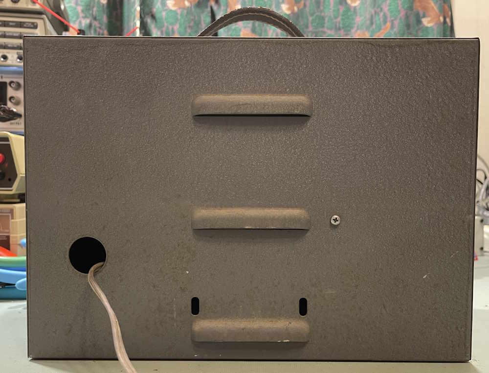
The back of the unit is nothing special. The cord simply runs out of a hole and is strain-relieved inside.
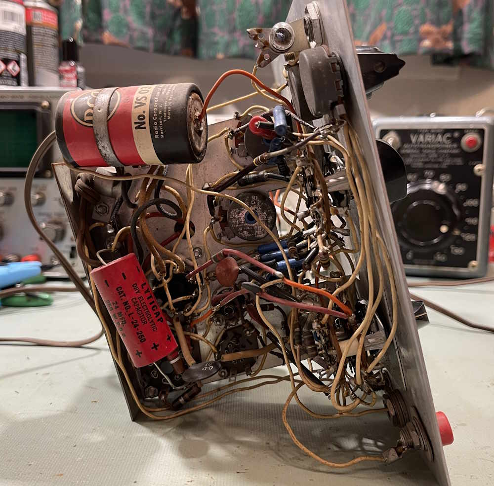
Inside, we have a wiring nest.
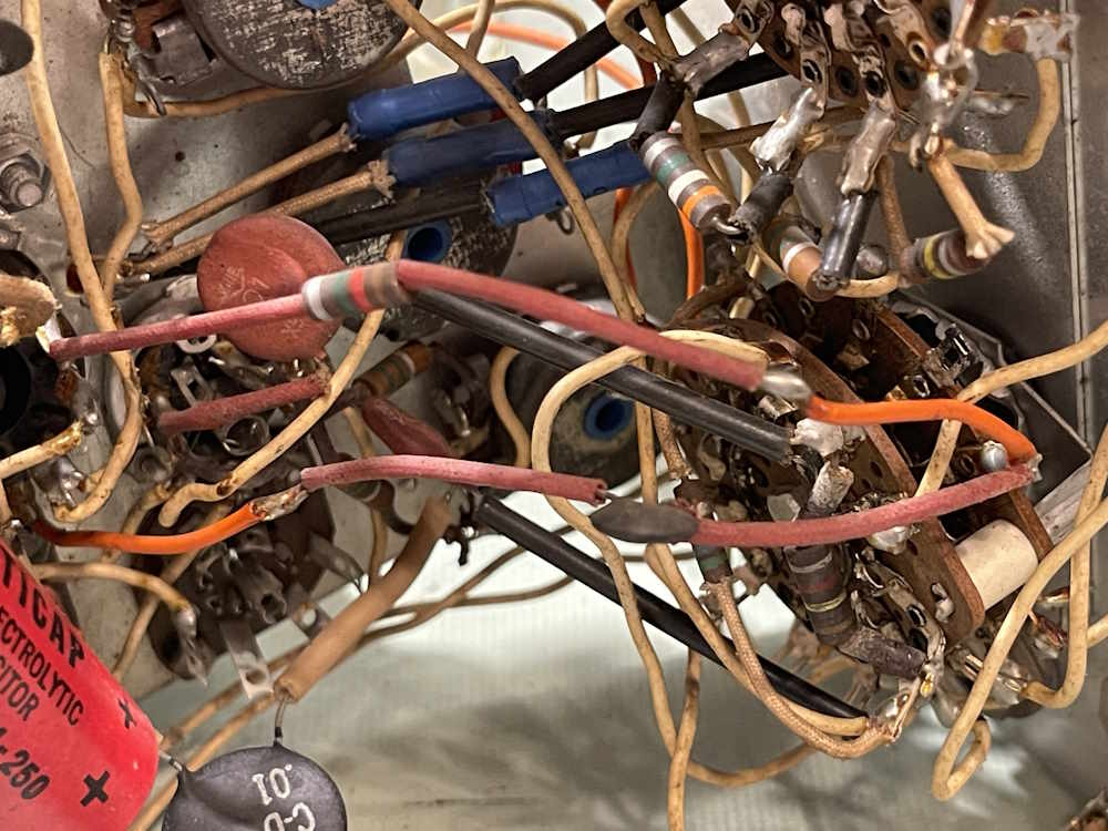
There’s our friends, those blue carbon film resistors. Jay Hooks makes an appearance as well, although it’s done in a much nicer way than the EICO 950A was.
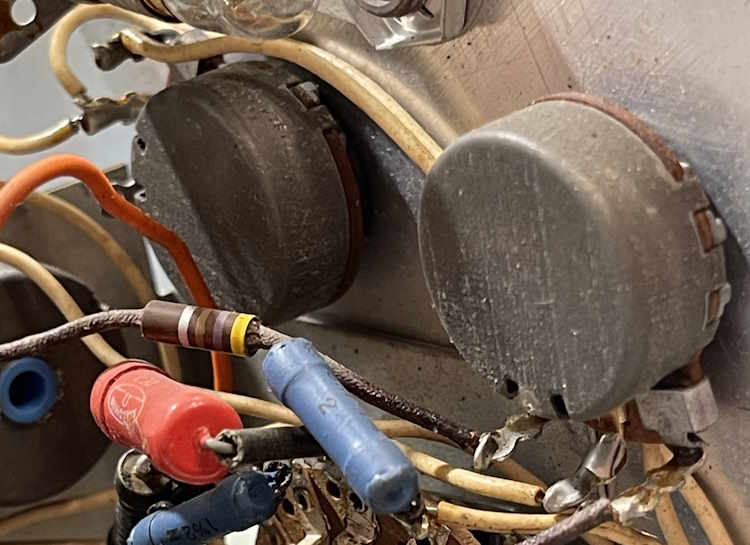
The control potentiometers are well blackened, as if this device spent some time in a wet or harsh environment.
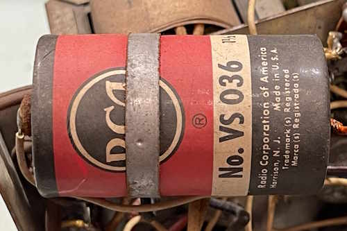
Here’s our old friend, the RCA battery for the ohms function. This thing hasn’t been touched for a long time.
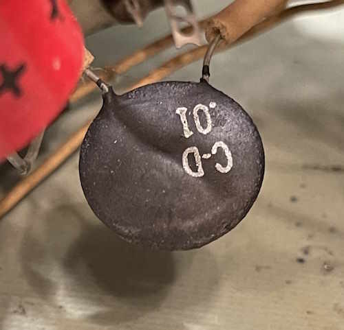
And some cool old C-D capacitors. Everything in here is disc.
I’m not sure if this unit was a kit, or if it was a factory build. Everything is covered with spaghetti, so if it was a kit build it was well done. I do have another example of this unit on the way as a donor, so we’ll see if it’s built in the same manner. I will say that it has some parts that have been replaced over the years, so who knows.
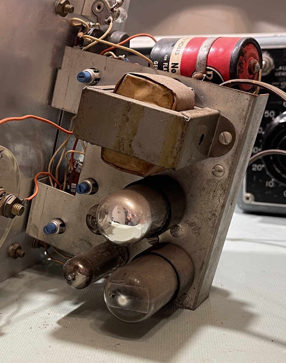
What makes this unit unusual? This one has 4 tubes.
It has these tubes:
6X5 as the power rectifier - no selenium here!
6SN7 as the input isolator/amplifier
6AL5 as the measured signal rectifier
0A2 as a voltage regulator
That last one is the odd man out. This device has a regulated power supply, so it should be somewhat immune to line voltage variations - something other VTVMs of the era had trouble with.
Does it work?
Sort of.
I did some quick checks on the unit, the filter capacitor didn’t seem shorted, so I plugged it in raw. The tubes have a lot of hours on them, but they lit - I didn’t see the voltage regulator fire so something is wrong in there. It does measure, but it’s way off and started to drift all over in the few minutes I had it up. So, it works, but is not operable as a voltmeter. But it does work, so it’s a good restore candidate - and it will have it’s time on the bench at some point. Stay tuned!
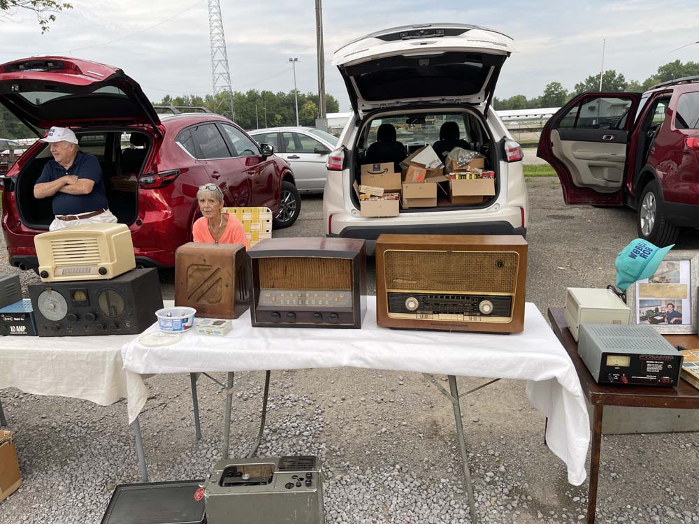
The 2026 Cincinnati Hamfest happened this weekend, and size-wise it was about as big as last year’s event. I spent just under 2 hours wandering the grounds a couple of times, and picked up a few things.
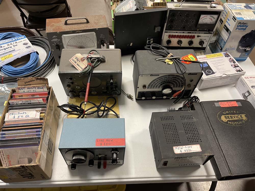
While it did rain, it held off for quite a while. Prices were generally pretty good, but there was one guy that was selling stuff that made me question what was going on - including someone’s printed-from-the-internet manual copies for $10. I guess you were paying for the “Estate Sale” sticker. not sure what that had to do with it, but it’s free on BAMA. I seem to remember this booth from last year, and it was the same…my companion and I both looked at the stuff and said what? There was also the usual assortment of “I bought it at this price!” prices on things, but you can get it for less new.
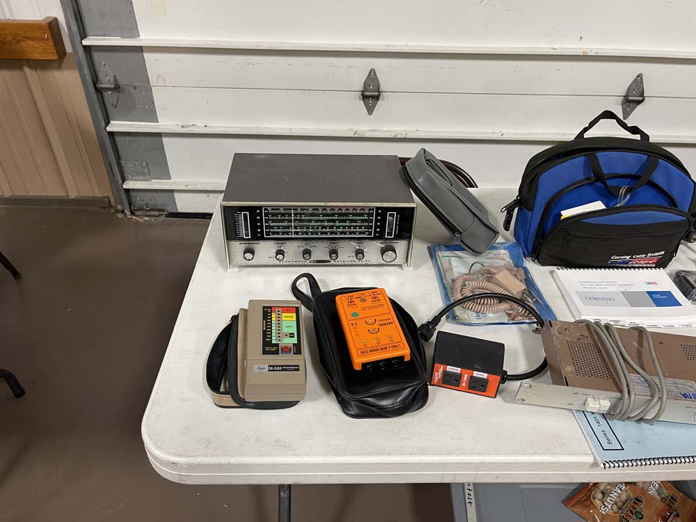
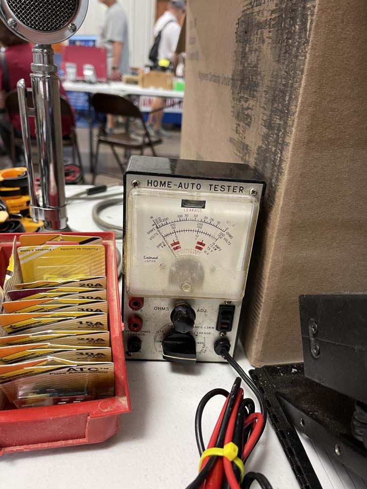
There was one of those little tester boxes I wanted to take with me, but the guy said you have to take this big box of consumer cables with you. I didn’t want to carry 30 pounds of F-connector and RCA cables away just to toss them in the trash - and in the trash they would have went.
There wasn’t much else I wanted to take home other than a HP334A, but I have no use for that. So it stayed.
A couple of anchors. I took the rowboat anchors.
These weren't well priced.
Some big old rack mount units.
A lovely Majestic console.
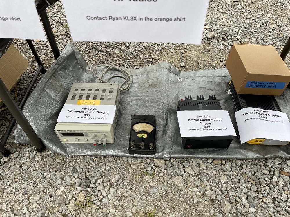
I took the little Welch ammeter.
Still plenty of these around.
Some Tek chassis units.
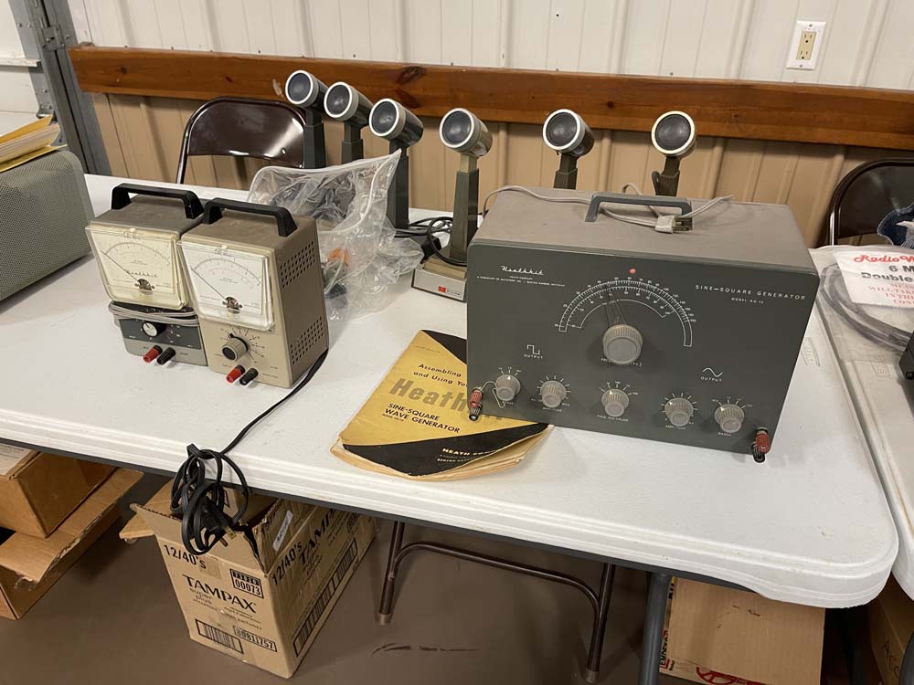
I wanted to take this but not the giant box of cable with it.
In all, a pretty good show. I went with a friend, we went to a local place for lunch that we both like, and ended the trip with a stop at Jungle Jims.
The Cincinnati Hamfest is happening this weekend, Saturday, August 15th at the Clermmont County Fairgrounds, just east-ish of Cincy. I went to this show for the first time last year, and it was a good regional, with enough different stuff that I’ve decided to go back this year. See you there!
Cincinnati Hamfest
Saturday, August 15th, 2026
8A-4P
Clermont County Fairgrounds
1000 Locust Street
Owensville, OH 45160