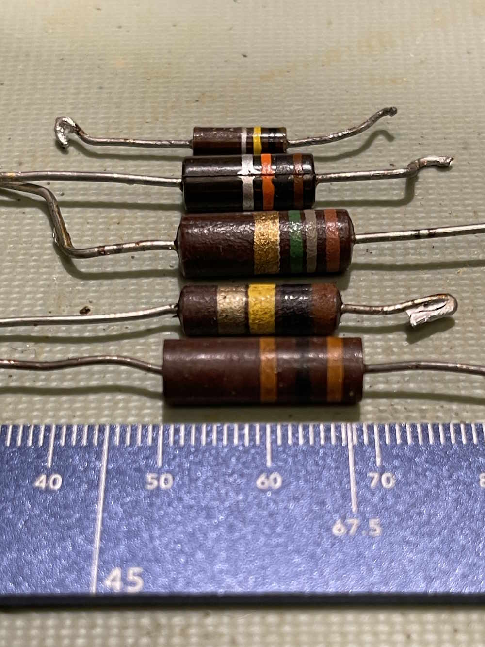
If you’ve worked on tube devices, you may have seen a resistor that looked like a higher wattage part, but was strangely long. For example, this 30kΩ 20% part in this EICO 950A RC bridge. It’s somewhat longer than other carbon parts:
Why is that?
Simply put, it’s for voltage ratings. This particular circuit has that 30kΩ part bearing the brunt of B+, and the entirety of 500VDC can be across that resistor A smaller carbon resistor would arc across and flame out.
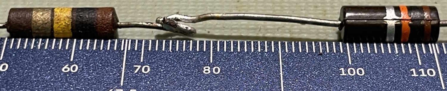
Here’s a couple of examples. The first is a comparison with a 1W resistor.
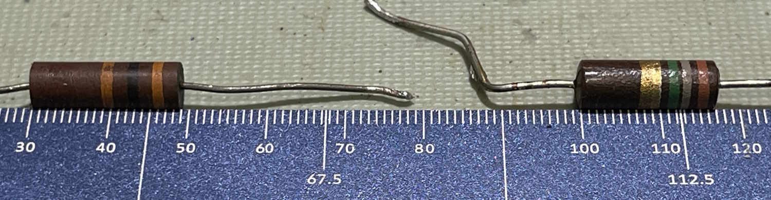
And a comparison with a 2W reisistor.
For the 1W comparison, the higher voltage part is 16mm long, whereas the 1w part is 13mm. The 2W comparison offers a 19mm higher voltage part, and a 17mm 2W device.
This is purely to provide physical spacing between the two leads. More space, less chance to arc. If you see one of these unusually long parts, there’s something special about that circuit, and it demands your attention.
This is something that I just learned not that long ago, so…now you know!
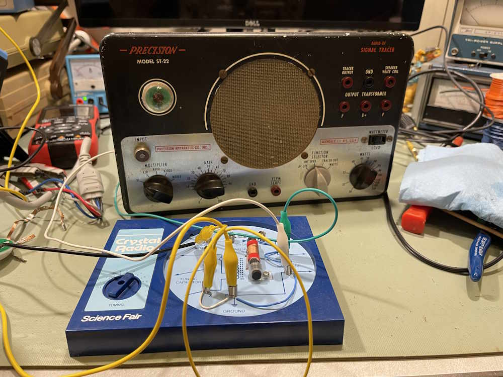
A “crystal” radio, or an AM radio that works without any kind of power other than that generated by the radio signal itself, is one of the staples of basic electronics. It’s something that’s always fascinated me, and while I’ve never wound one by hand I’ve built a few kits over the years and generally enjoyed them. It’s so named because originally, these would have used a chunk of some natural semiconductor like galena to make the detector - but in a modern sense we use a small crystal of germanium in a 1N34/1N60 type device.
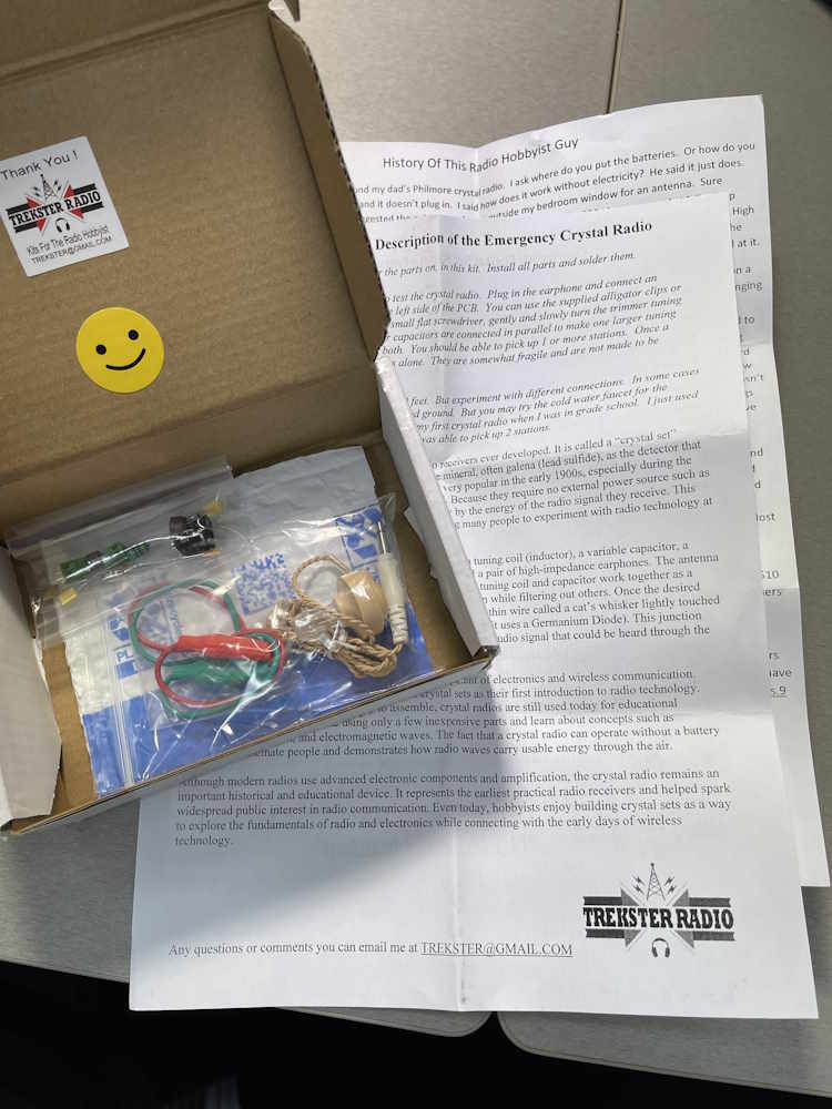
This particular device is sold on a popular auction site, and is offered by the creator. What’s in the box?
Packing material! Just what I wanted. No, not really.
A couple of sheets of instructions, a couple bags of parts, and a PCB.
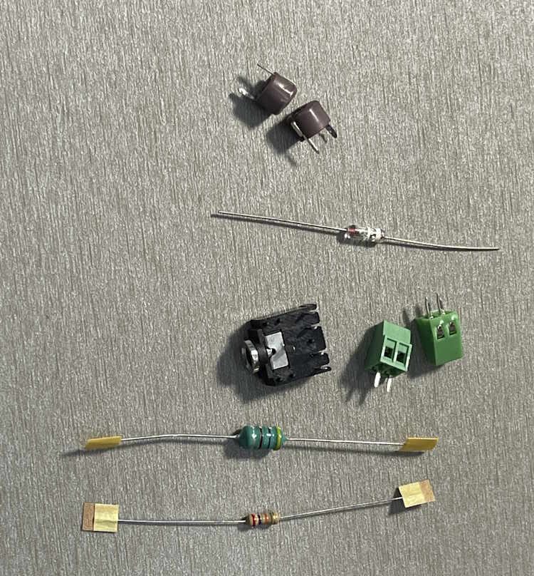
We have:
Two variable capacitors
A germanium diode of type D9K
An earphone jack
Two screw terminals
An inductor
and, a Resistor.
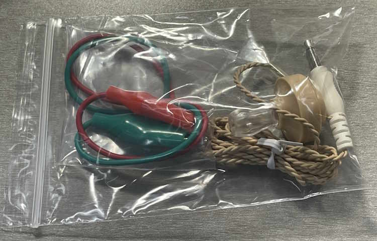
In the other bag, we have:
Two cut clipleads
A Piezoelectric earpice
Those of you who have been around for a while will recognize that earpiece as the same one included in every Radio Shack kit ever made. There are lost tribes using these as jewelry somewhere.
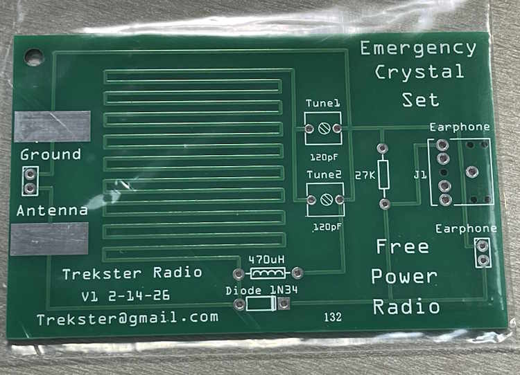
Also included is this PCB.
The board itself looks nicely made, and uses the copper as part of the inductance for the circuit. The only thing I see right off is the diode is going to be a tight fit with the leads bent down right at the body of the part. That’s not really good for a glass part, and hitting that with heat can cause damage - especially if you’re not careful to get in and out asap.
But, I think it should be ok. We’ll see, I’m going to build this kit within the next few weeks. There will be one more post about the building and testing, stay tuned!
The Cuyahoga Falls Amateur Radio Club hamfest is happening this weekend. Located in it’s namesake of Cuyahoga Falls, Ohio, this show occupies most of the floor space of an old grocery that was converted to event space. I’ve always been able to get some unique stuff from this show at good prices, even during what I would consider bad years.
You can also visit what was up until last year, one of the few remaining Arthur Treacher’s restaurants. It’s literally down the road a mile or so from the event.
I’ll have pictures from the event posted ASAP.
See you there!
Cuyahoga Falls ARC 70th Annual Hamfest
Emidio & Sons Party Center
48 E. Bath Road
Cuyahoga Falls, Ohio 44221
Saturday April 11 2026
8A-1P
Admission $10
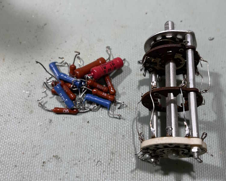
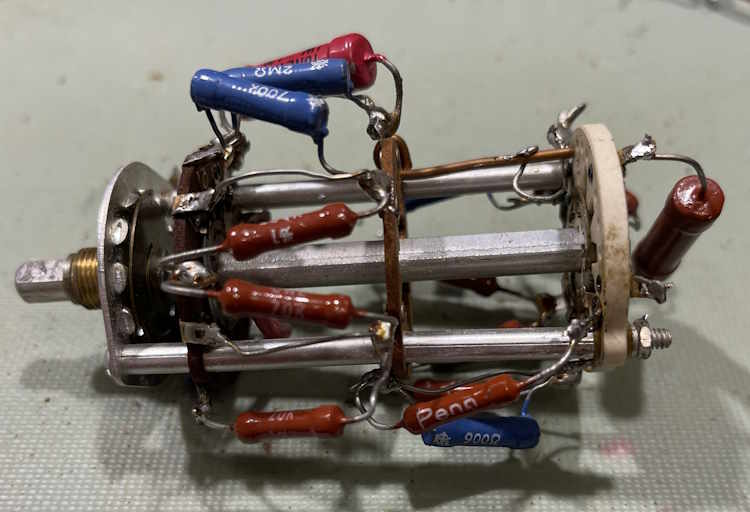
Instead of removing the range switch from the good unit and trying to rebuild it, I’ve decided to use the switch from the parts unit. It has some modifications to try and correct poor connections, but a good cleaning with Deoxit on the wafers seems to have taken care of this.
In order to try and save a little time, I measured the components already on the switch. There are quite a few of them that fall within tolerance:
Quite a few of them, in fact.
However…
These are most likely old carbon deposition resistors, aka carbon film. The minute I hit them with a soldering iron to remove their out of tolerance neighbors, they started to change. A lot. I kind of expected that but was hoping it wouldn’t do that. So…
They were all removed and will be replaced with new metal film parts. In the meantime, the switch has a date with the ultrasonic bath, and will be re-greased once done.
Welcome to visitors from blogosphere.app and lobste.rs. This blog is a personal account of the old tech? junk? I work with on a personal basis. This is just for my own education, not to make money or anything else, and with the hope that some of the things I present here will help others in their quests to keep this old stuff going. There’s a couple of pages you may be interested in, the first is the main project hub, and the 2026 Hamfest list / show pictures page. All of these are on the sidebar, including previous years’ pictures.
Thank you for visiting. Now, on to the show:
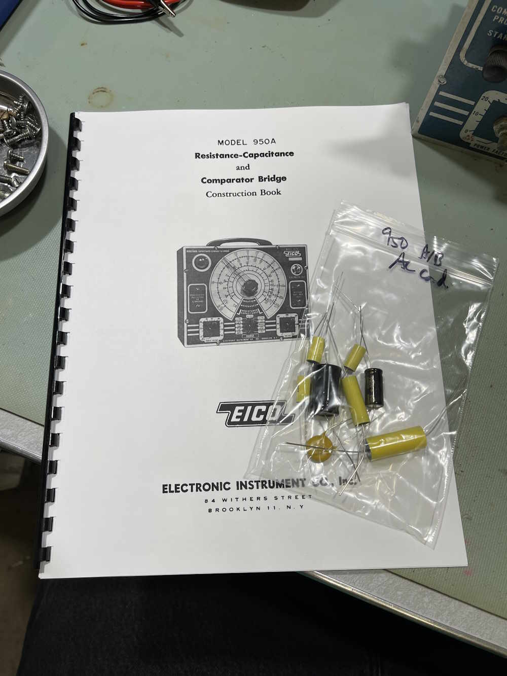
In the last post, we determined that this device is going to need some serious corrections, aka complete rebuild, in order to be safely functional again. The previous owner, while they used decent quality parts in the unit, attached them in such a manner that I have to wonder what was going on. It’s just…what? You can find the link to that post near the bottom of this page.
Since then, I’ve acquired a few things:
A manual, essential because there’s no schematics online for this particular variant, and a pre-made kit of parts containing all of the capacitors for the device. The latter is more of a convenience thing, but it seems to be a kit of good quality parts at a reasonable, one-off price.
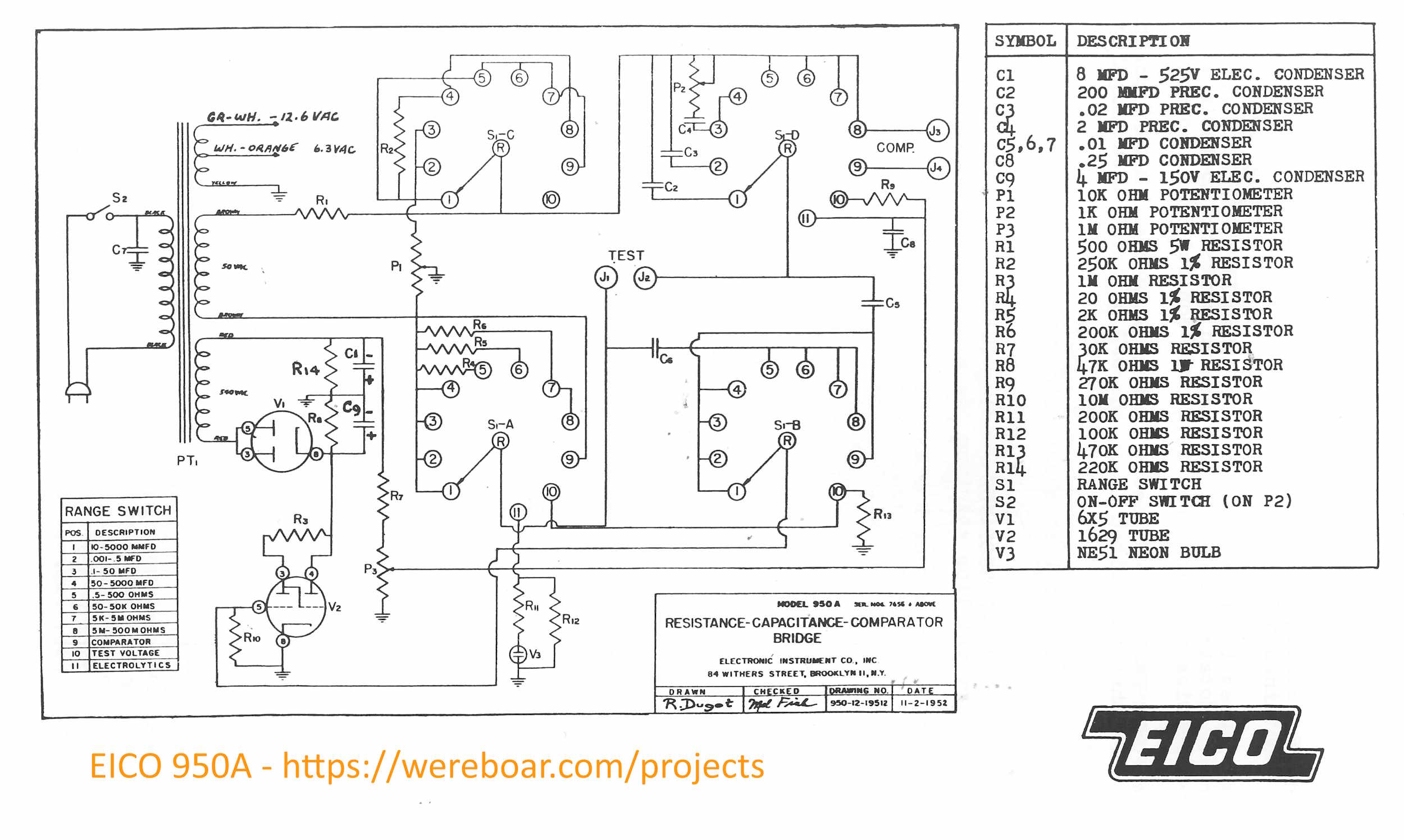
Speaking of schematics:
This is a 2500px-wide image, and should be decent enough to print on an 8.5×11 sheet for use.
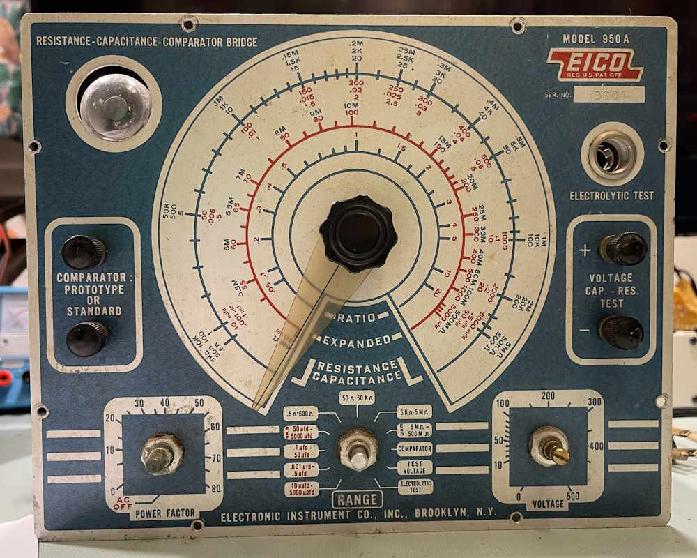
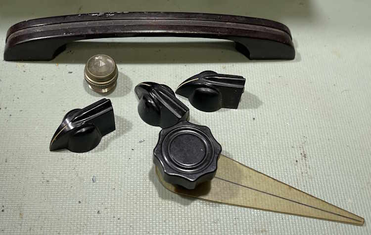
As part of the process, I’m going to take all of the knobs off and dump them in the ultrasonic bath. But first, where is the main dial’s limit?
And they all come off easily except the binding posts.
The binding posts need to come out of the chassis to be cleaned.
I’ll unsolder those, clean them, and remount before anything else happens. The case itself, as rusty as it is, will also get a good scrub. I don’t repaint these, I like the used look.
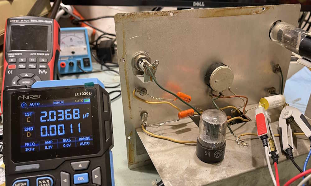
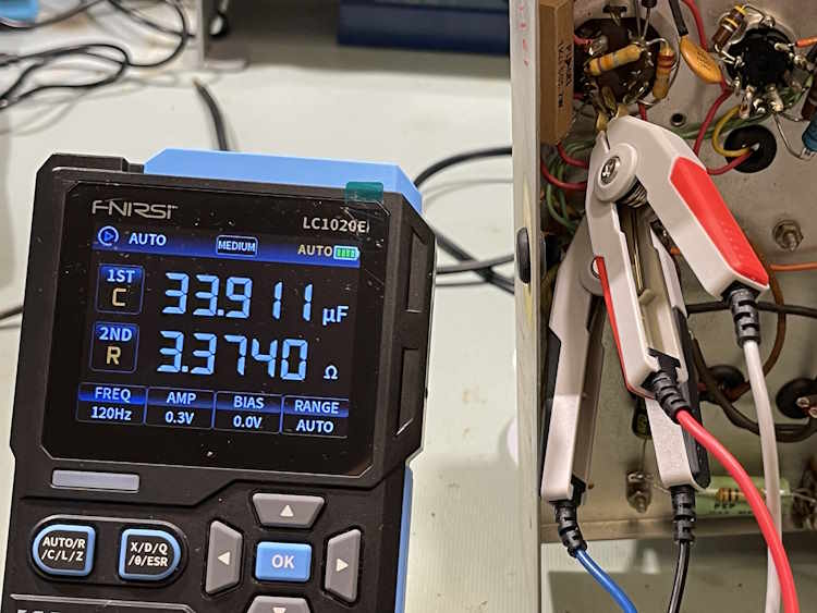
Let’s do a quick test on one of the parts in the unit. This is the main 2.0μF “precision” measurement capacitor, and this one was replaced at some point by the previous owner. Datacode is 70s, but that doesn’t mean anything more than that’s when the part itself was made.
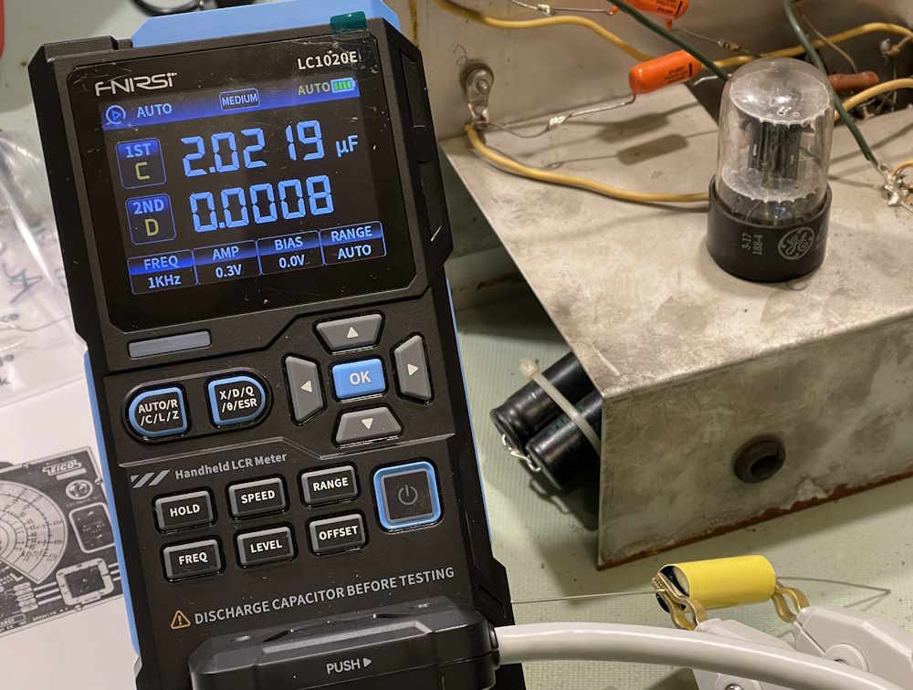
It’s under 2%, that’s pretty good. The new one:
That’s about 1.1%, so this one is marginally better.
The next thing to do is go through my parts and see what I have, and then order some resistors. I already have the big 500Ω 5W part, this is leftover from the Olson TE-189 Rework project. That device and this one share very similar schematics - but then again, it’s not like there were many ways to do this type of thing with line frequency and a tube…
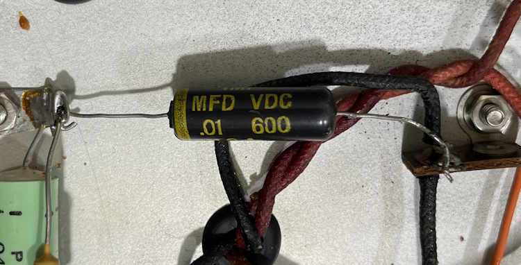
A quick note on parts here: In tube devices, you’re often dealing with voltages much higher than you’d encounter elsewhere - this unit, for example, has 540+ VAC on the transformer output. Not only should you take caution, but you need to be aware that certain parts must have certain ratings. Capacitors, sure - but resistors as well. Take this 30kΩ resistor for example. This is R7 on the schematic, and takes the full brunt of B+. This can be in excess of 700V under the right conditions, and this will destroy a normal resistor.
It’s hard to see in this picture, but the resistor is longer than others - this is to provide more isolation between B+ and the load / ground / etc. In this case, make sure your resistor is rated properly - I’m going to use two 15k 500V devices to halve the potential on each, which should reduce risk. I’ll do a better comparison once the parts are out of the unit, including a measurement post.
I have all of the parts ordered, but the Cuyahoga Falls Hamfest is this weekend and I am going to see if I can get a few of the components there. If not, I’ll order parts and we’ll start the rebuild in earnest. Stay tuned!
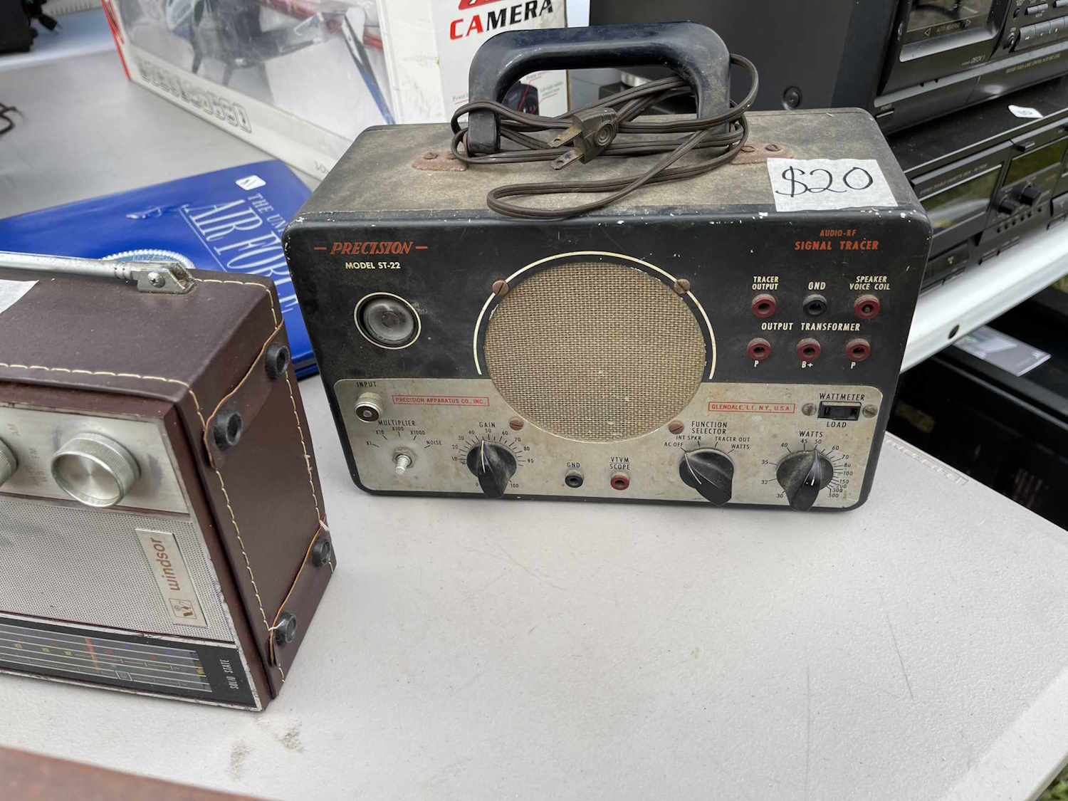
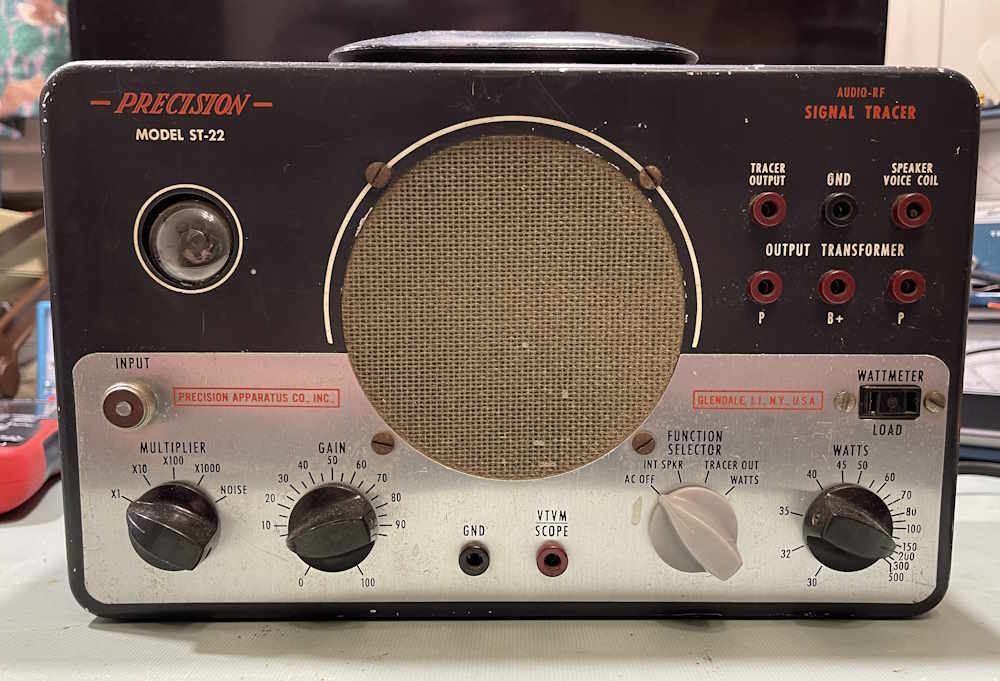
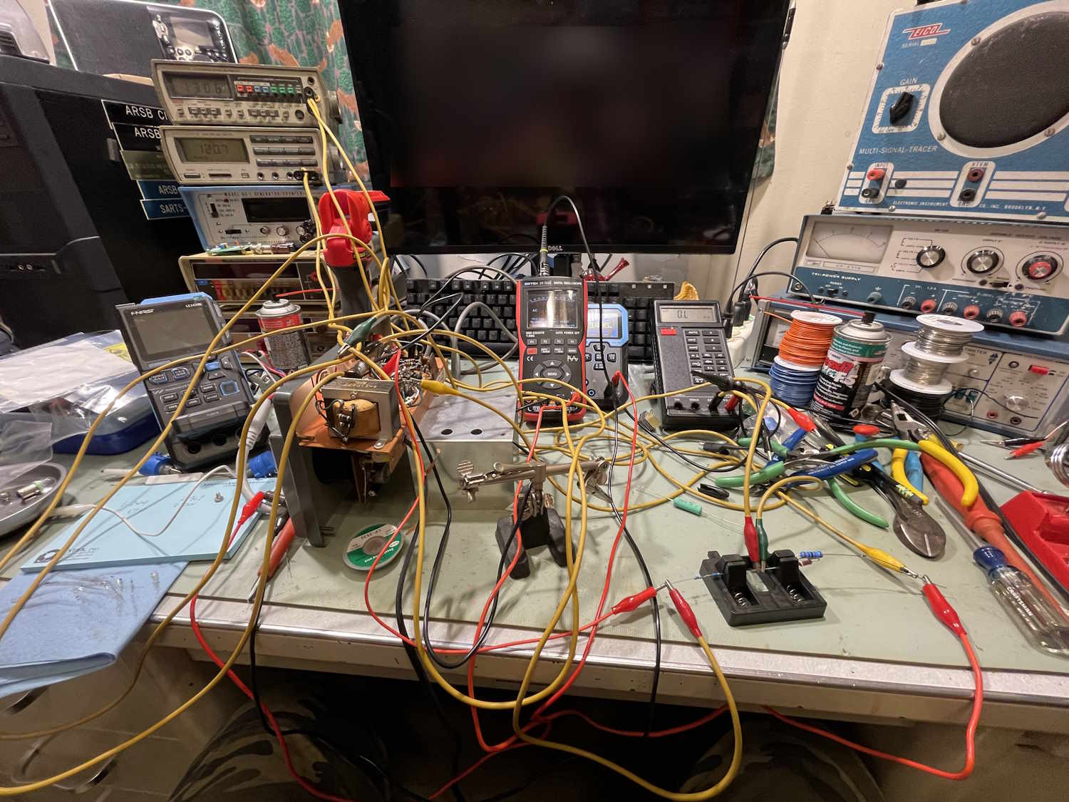
This is a device I picked up at Dayton 2025, mostly because it was cheap, and was being ignored because it was very dirty and wasn’t a desirable EICO unit.
This is how I found it:
And how it cleaned up. It was missing a knob so I pulled a gray PACO knob from my stock. Same knob, different color. Yeah…the selector control should have had a different color on it, that’s the way it is…
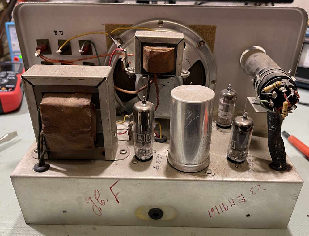
This one might have been a factory build. There are names on everything as if multiple people had their hands in this.
The tube compliment, save the eye, is all Precision or PACO branded. Either this has it’s OEM tubes from the original sale, or the owner replaced like-for-like.
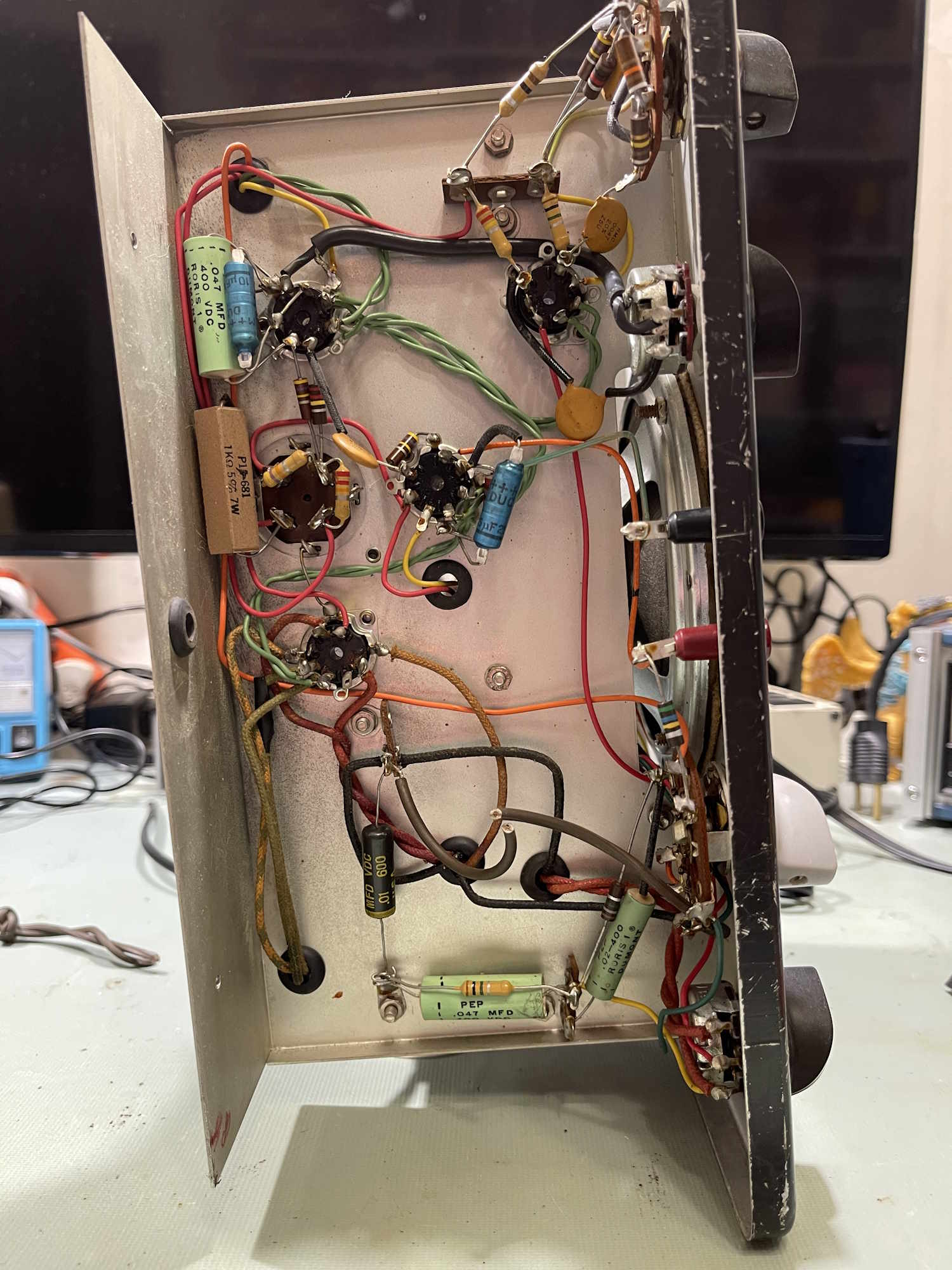
The bottom of the unit is quite lovely. All those old Dumont capacitors, tho…
Notice all of the holes are grommeted for wires. Quite a different level than other manufacturers.
Even the eye tube is held in with a band made of wire.
But…
Fortunately, the chassis is return, but that still probably caused some noise.
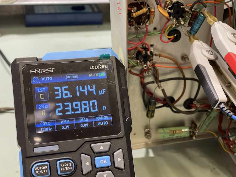
Some basic checks on the unit before applying power…
That one is no good.
That one is ok. Kind of.
I’ll have to do some other checks with voltage later. I’m curious as to how well the Dumont capacitors held up.
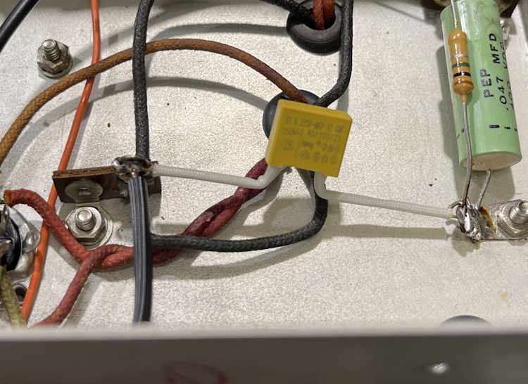
There is one part, however, that needs to go, and that’s this across the line capacitor:
A new safety rated part was installed.
So…does it work? Sure does:
The eye tube is just about as dead as can be without being unusable, so this thing has a lot of hours on it. The gain control has a thunderstorm in it after multiple cleanings, so that will need to be replaced. Other than that, if may be a use as-is assuming the electrolytics don’t go popboom. I’ll still do some diagnosis on it to see if any resistors are way out of tolerance, or any of the other capacitors leak. Some will need to go, but the rest? Who knows.
This model seems to be somewhat unusual. The PACO Z-80, which looks like this one save it doesn’t have the chart diagram on the left side, appears to be identical. I can’t find a manual listed as the ST-22, so I’ll compare to the Z-80’s schematic and see if they are the same.
Stay tuned, this one will be on the bench maybe later this year if I have the time.
Another selenium-laden device. Why do I do this to myself?
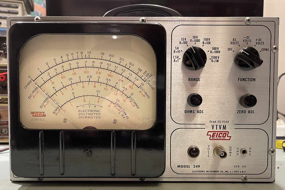
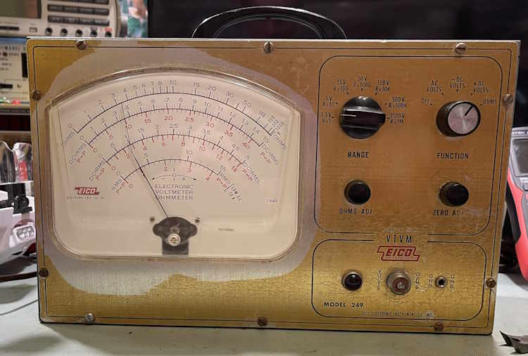
The EICO 249 (And it’s small-form-factor cousin the 232) are VTVM units that offer both a P/P and RMS scale on their wonderfully large, but not parallax corrected face. It offers VDC, VAC, and Ohms (via an internal 1.5V battery.) These date to the 1960s, and as such, are probably one of the last-gasp devices that had both tubes and selenium rectifiers for the power supply.
The EICO 249 - The repair candidate
This unit came from the Cuyahoga Falls ARC hamfest along with the PACO G-30 that was on the bench earlier. It was the same vendor, so it has similar repairs inside - including replacement parts that don’t meet certain specs of the unit and will need to go if this wants to be in service.
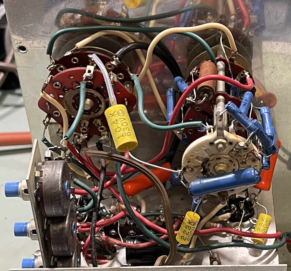
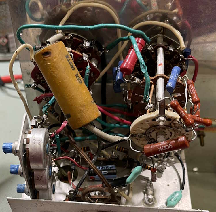
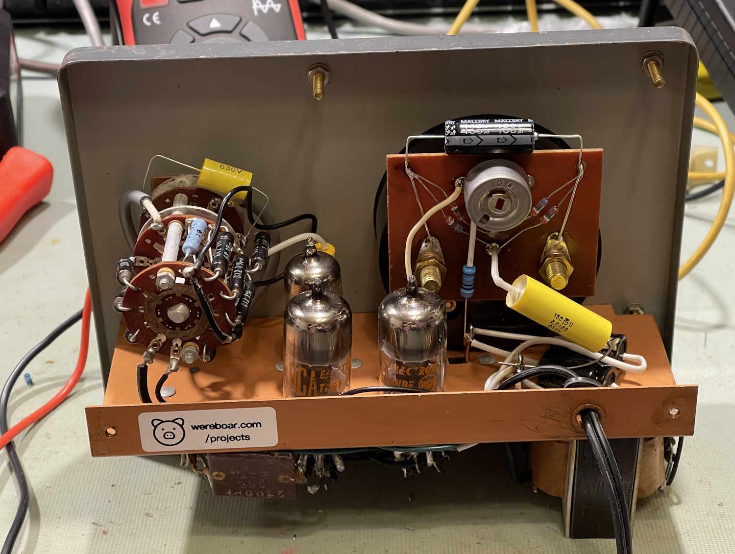
The inside of the unit shows obvious work. It’s organized chaos.
Is that a polystyrene part in there?
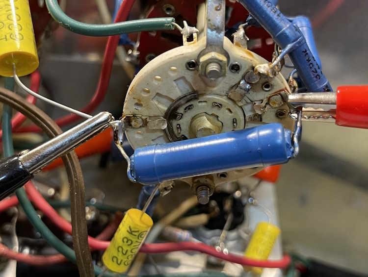
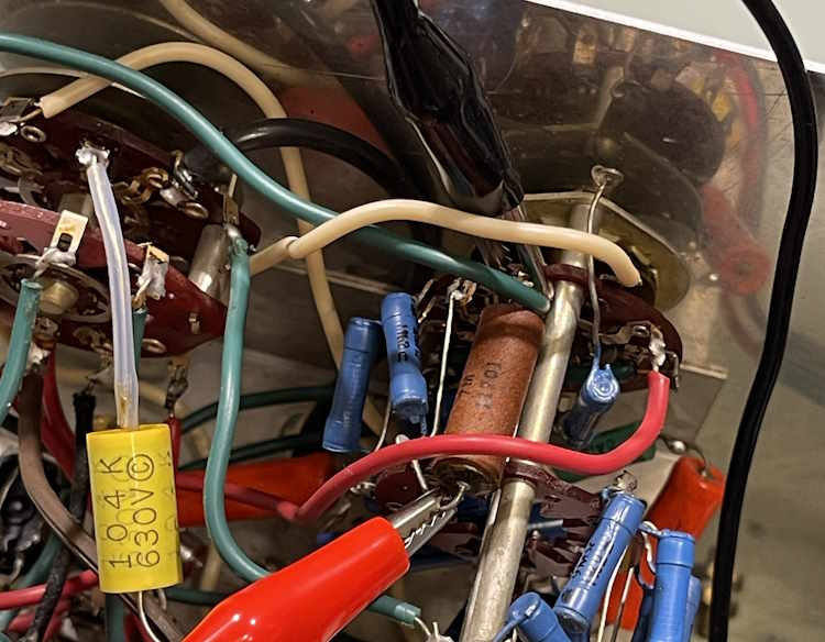
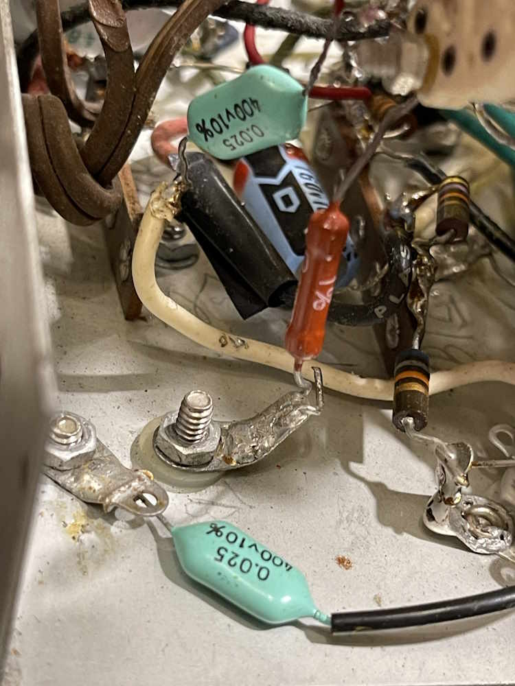
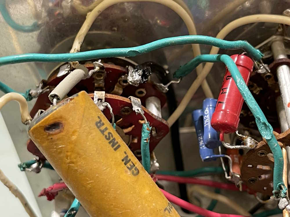
The capacitors have all been replaced, as have some of the non-divider resistors. The orange parts near the bottom aren’t capacitors, but big resistors chained together to make some value. Front and center, however, is the 0.1µF @ 630V capacitor. This one is called out as 1000V in the specs, as this is an input blocking capacitor and may see a higher voltage on the input. The person doing the replacement just used a regular part without considering why that voltage was chosen. Of the most interest, however, are those blue resistors on the switch assembly. This is the voltage divider ladder, and we’ll come to that shortly.
The wiring seems to be thick and rubberized, and some is breaking down. It will need to be replaced as well, although not all of it.
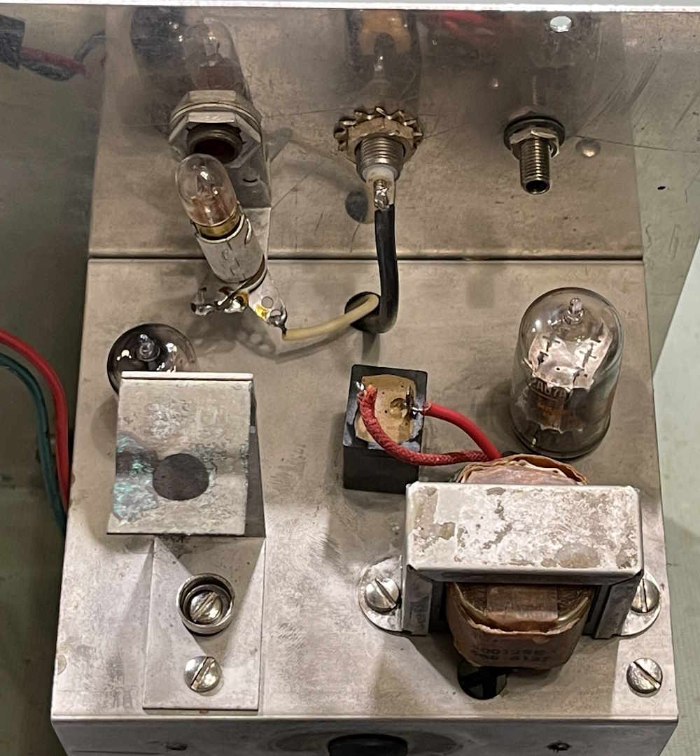
The bottom of the chassis has the input jacks - the input was replaced with a BNC connector - the tubes, transformer, battery holder for the ohms function, as well as an enclosed 35mA selenium rectifier. This particular unit uses a split rail supply, so it’s going to be interesting seeing how it reacts with a modern silicon diode instead of this non-linear rectifier.
B+ total is about 150VDC between the positive and negative rails, so it’s not going to be difficult to work with. I question the use of a 150V filter capacitor in this circuit, however…those old paper caps did things differently and I’d probably chose a 200-250V part these days.
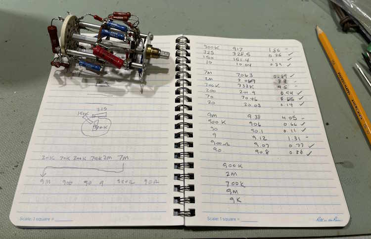
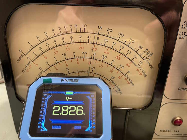
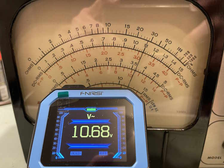
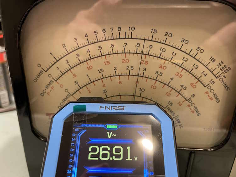
How does it perform? It’s…accurate-ish. Some scales are ok, others are not.
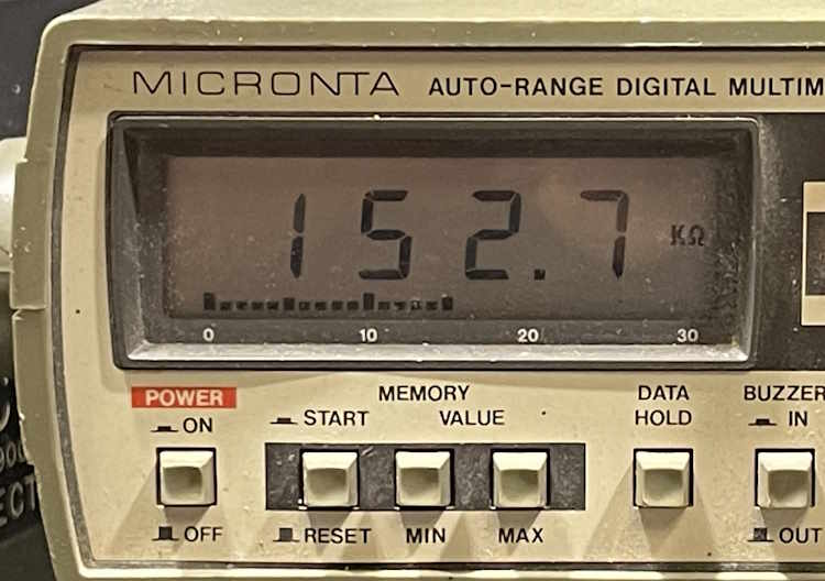
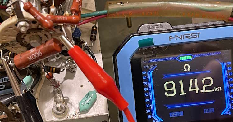
While the voltages were close after dialing in a test point with the adjustments on the side, they’re still off. That’s because the resistors in the divider ladder are all out of tolerance. These were 1% parts when new, and have simply drifted some over the years. That it’s not much is a testament to the quality of the parts themselves.
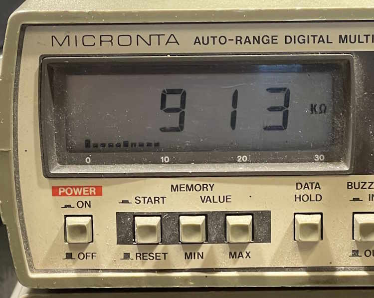
150kΩ
900kΩ
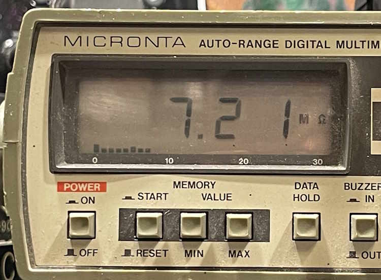
7MΩ
Others in the ladder were similar. They’re all bad. While 2% may not seem like much, it’s all of them in series with one another being off that causes drift and deviation. The unfortunate thing here is that most are unusual values and will require some chaining to replicate. Fortunately, these values can be made with standard values either in series or parallel.
The EICO 249 - The parts unit.
Setting that one aside for now, I have a second unit. This unit was purchased on fleebay, and the person packing it didn’t pack it well. The box was destroyed and the meter movement was damaged. That’s kind of a shame because this movement was the later, clear style. At least, I think it’s later…the date stamped was 1968. The golden color on the face is the glue from the original paper protector material, the paper apparently not having been removed until too late. There was still evidence of it under the nuts on the controls.
This one still has a lot of it’s original parts inside, with some old replacements. This one no longer had it’s selenium device, someone had put a diode in it without considering the effects of the much lower voltage drop on the power supply. I wonder how well that worked? I won’t know because it wasn’t functional when I got it, the meter being jammed to one side and coming unstuck broken.
This one is a mishmash of garbage and sadness.
These capacitors didn’t measure anywhere near the marked values.
Wiring was burnt. Almost every wire. Every. Single. One. Even the big 1000V capacitor in front of us is burnt.
How are the resistors in this one’s divider ladder?
About the same. There’s a couple in there that are right on, so…maybe I’ll take them off and see if they can be reused.
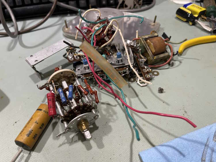
However…this one is not a unit that I can save, so it’s parts. Literally, a pile of parts.
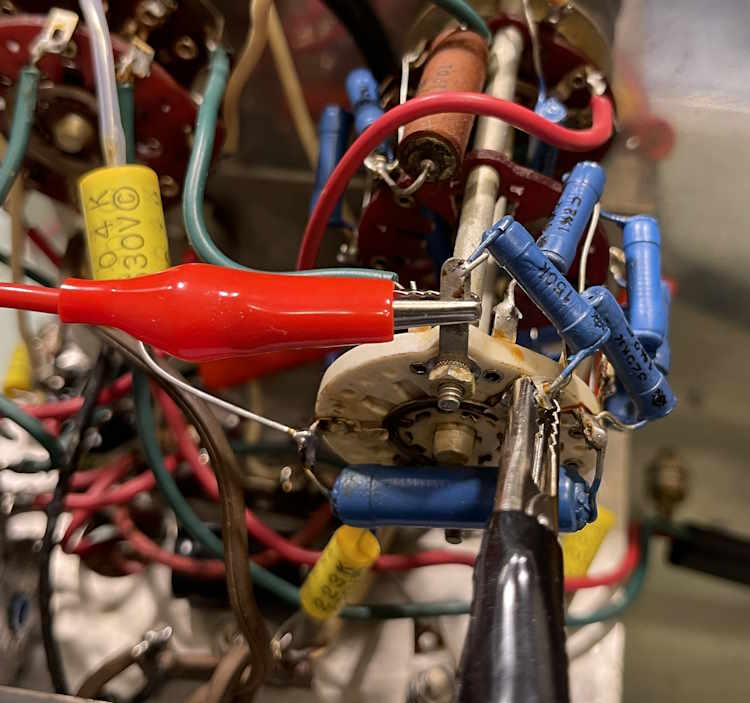
But, all is not lost. The range switch may be a candidate for out-of-unit rebuild. I took some time to remove a hold-down mod the person put in for one of the contacts, and cleaned the metal rings. It seems to work ok, so I’m going to try it.
This thing may have a good chance of living again. Stay tuned!
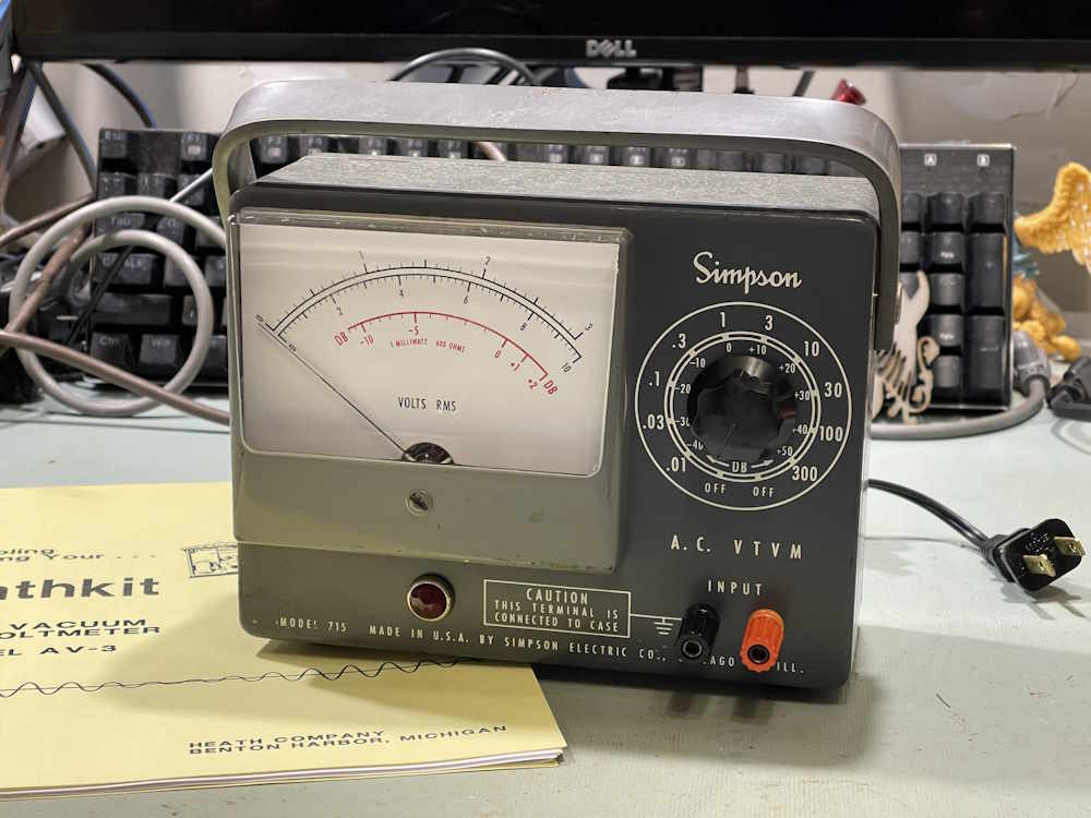
The Simpson 715 is still somewhat of a mess, but I knew that going in. With almost any meter of this age, the resistors in the divider ladder are going to be way out of tolerance. While I didn’t measure any of them, voltage testing suggested that it starts at the bottom - so yes, literally all of them are probably bad.
I’ll revisit this device later, but right now I have other things I want to work on, and determining what resistors are going to be needed will require some thought.
This device didn’t have any real data about it, so I wasn’t sure what anything was supposed to be - plate voltages, tube voltages, etc. Fortunately, Simpson made this unit for Heathkit as the AV-3 kit, and Heathkit’s manual for the device was their normal, packed full book. All of the information was there and that helped considerably.
The original problem I was trying to correct.
The original issue with this device is that of no zero. While the device still doesn’t necessarily zero like I think it should, it’s much better than it was. I suspect there’s both some resistors bad in the unit itself, and that the meter movement may be a bit flaky from being beat around over the years.
As this was a piece given to me by a now-departed friend, I wanted to at least make sure it did something, and that it does. For the most part, I simply replaced all of the capacitors in the unit as they were old wax paper, bumblebee, and other assorted relics from a bygone age.
That was very straightforward and didn’t incur any issues.
The Selenium Rectifier
The selenium rectifier didn’t really present any challenges save that it stopped working midway through my testing of currents in the circuit. This required some guesstimations, which were incorrect. I was eventually able to determine was the device wanted after some physical experimentation.
That experimentation involved going back and making a new guess based on some other real-world devices, and getting it correct. I wound up with a 1.27K resistor replacing the selenium stack, bringing both of my B+ values to within 0.5V of the rated value.
I had posted about this device elsewhere, and had someone tell me that I was doing this wrong and making it harder than it needed to be. They read online that a selenium device only has this much drop, and that I should simply use that information to design a regulated supply, hope that helps.
No sir, that didn’t help. Sorry. But if you have a regulated 130VDC/120VDC power supply that fits in a selenium stack space, please let me know.
Final Thoughts
As I said earlier, this one isn’t done - especially if I want to actually use it. It’s a cute little device, so I’d like to - but the meter movement itself raises some concerns. I’ll definitely revisit this later, but for now - it’s mostly operational, and it’s good to sit around for a while.
Next up is an EICO 249 that has a similar issue, that of the divider ladder being bad. I have a spare unit and can rebuild the ladder assy out of parts, on the bench. Stay tuned for that one.
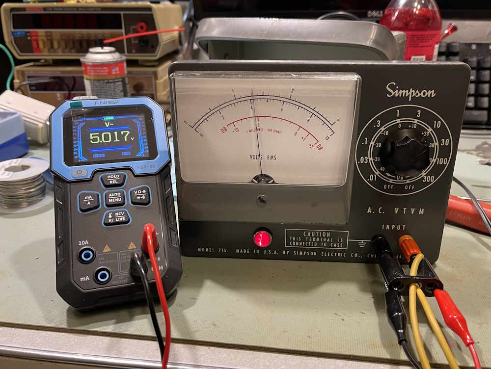
The Simpson 715 AC Voltmeter is finished. The selenium rectifier has been replaced, the capacitors are all new, and a few resistors have been changed out for good measure. So…does it work?
Well:
Yes…but no. It does work, but the resistors in the divider ladder are bad. I knew that going in. It also still has a hard time zeroing. Some checking suggests that pretty much everything in that ladder is out of tolerance, so if I want to use this device it’s going to need to go under the knife a second time.
I knew that going in, so it’s no surprise, and that will be a project all on it’s own - possibly. Stay tuned!
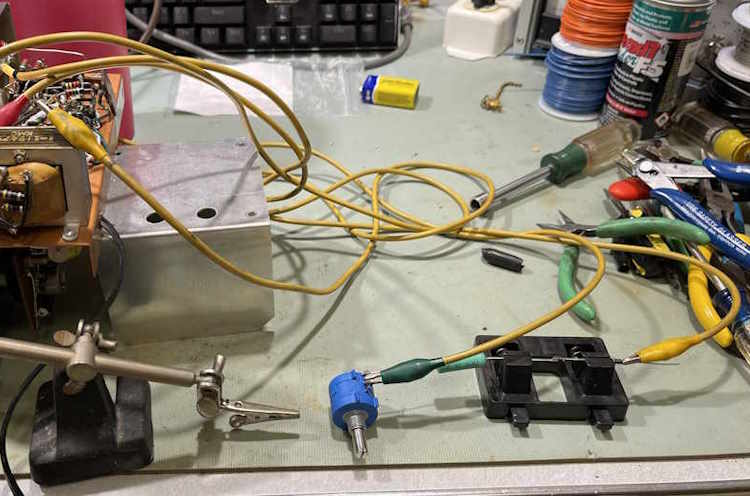
The selenium rectifier in the Simpson 715 isn’t going to replace itself, even though I wish it would. Therefore, it’s time to start the task of doing that. I started by making some assumptions about the current flows in each of the B+ sides…which were wrong. I knew that ~2mA flowed in the B-side of the power supply, but I had no idea what the A-side would be. This really didn’t make sense to me as there’s supposed to be 10V dropped across the B-side resistor, and 2mA would not do that with a 10k resistor - you’d need 20V dropped. Regardless, I left the 10K resistor in the B-side circuit for the first part of testing.
I originally started with my assumed parts, and quickly set those aside. I then went for a 1k resistor with a 200Ω pot, but found out that wasn’t enough. A 5k pot was chosen, and I was able to dial in the necessary 130VDC. I did the same thing with B-side, and after adjusting both pots I was able to come up with values.
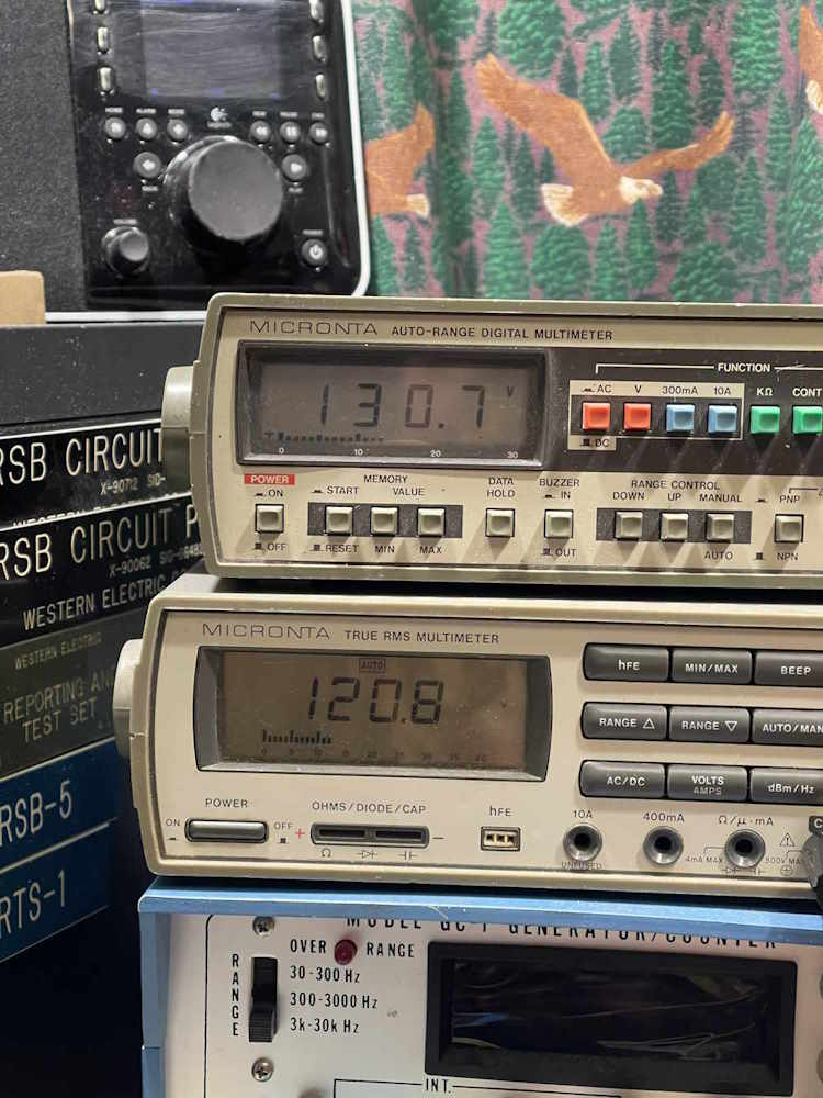
After testing, I settled on 1.27k for the dropping resistor (selenium replacement) feeding the A-side, and 5.168k for the dropping resistor feeding the B-side. With that, I now know that (approximately):
Input voltage = 123VAC
Rectifier output = 173Vp, or (Vin*1.414)-Vd
If we want 130V on the A-Side B+, we need a drop of 33V across the resistor being used to simulate the selenium device. That means in 1.27k, abot 26mA is flowing:
I=(Vdrop/Rdrop) or .0259A=33V/1270Ω.
10 volts needs to be dropped by the B-side dropping resistor, so that means in 5.168k, about 2mA is flowing:
I=Vdrop2/Rdrop2) or 0.0019A=10V/5168Ω.
So we now know that the A side is requesting ~24mA and the B side is requesting about 2mA, for a total current flow of about 26mA. Note that I’m using approximat values because these will fluctuate slightly with line voltage and with the tubes themselves actually doing something.
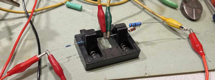
The actual values were slightly different, 1270 and 5170, but I used what I had - a 5100 and a 68 got me close enough, and I had a 1k and 270Ω in stock. The testing of these parts resulted in some organized chaos…
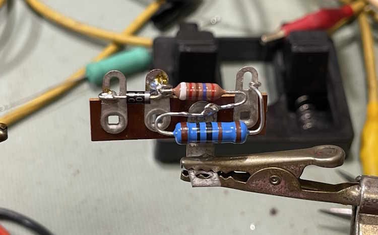
For the diode, I chose a 1N4007, for the specific reason that’s what I have a lot of in my parts stock. Mounting required removing the old selenium rectifier which was just screwed down:
And building it’s replacement on a terminal strip. That j-hook didn’t turn out quite as nice as I’d liked, but it’s solid.
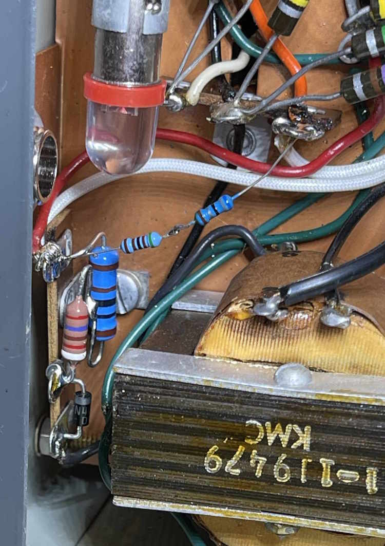
For the B-side B+, I used two smaller resistors since the power was negligible. They routed around the pilot lamp, but I would have liked to have higher power parts for this. Perhaps we’ll look into that later.
(Note the LED bulb in the pilot lamp socket. We’ll talk about that in a minute.)
B+ came right into the slots allotted for it.
Just on a whim, I tried a LED bulb instead of the #47 pilot. The circuit actually relies on the load from this part:
So it got replaced. A quick check, and on to the final checks…