I’ve been combing though all of the links about this device and it’s cousin the Lafayette TE-46A, and ran across a couple of videos from 2 years ago.
On a youtube channel called AllTheGearNoIdea, two videos regarding the unit were published. The presenter talks about the device and some of the things done to it in the name of making an older device stable for modern use:
In the second video, the presenter tests the newly re-capped unit. He runs through some of the ranges just like I did, only to find they did not work as expected. He was using modern capacitors as well, so I wonder if that has something to do with the problem.
While I don’t have any old paper capacitors at the moment, a piece of equipment on my to-bench list has several it will happily donate.
There was also a link presented that had a much better schematic than the original - it’s at least intelligible instead of “Hey Bob, can you draw me a schematic? This goes into production in an hour!” schematic that Lafayette/Olson presented for the device.
I’ve reached out to the youtube channel page contact. I’ll post more if they reply with something interesting. Stay tuned! (December 2025: They have not responded, I have no expectations that they will.)
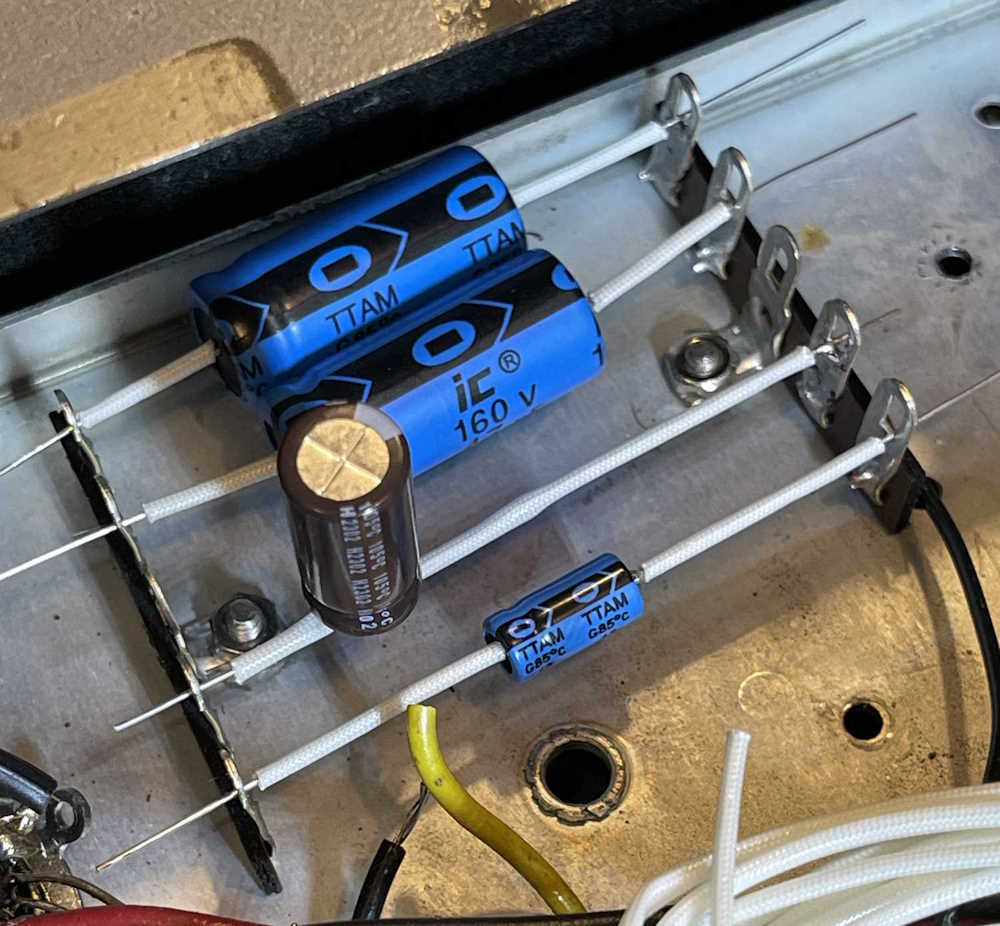
The original capacitor for this unit was a multi-unit paper tube, and I’m not going to dig the potting out of it to see if I can fit new parts inside. That’s just not going to work, and I don’t care about “looking original.” I decided to use the time-tested method of some solder lug strips and discrete capacitors.
After removing the other one I put in there (and made a mistake with) I settled on these 5 lug strips - one for each capacitor. Since the chassis is hot, I ignored the center terminal and grounded the 4 outer terminals on the back lug. The front lug will be the actual connection points to the individual capacitors.
The only real consideration here is where to place the parts. I thought about doing it this way first:
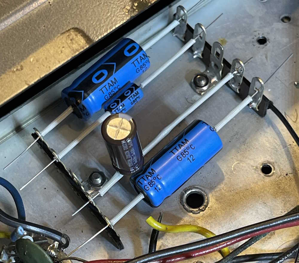
but the two big 47s push on one another. I decided this:
was probably better, as the circuit doesn’t care about where they are, just that they are electrically connected to the right point. It gives everything plenty of space.
Next step is to form and solder, then run the connection wires. Still waiting on that blue wire!
Tickets for the Dayton Hamvention are currently on sale at the early boar price of $26 - this is good until March 1st, at which point they’ll go to the normal $30.
You can order online for convenience, and doing so now allows plenty of time for the postal service to deliver them to you - especially if you’re not in the USA.
This guy has sat around long enough, and I finally have new feet for it. Since this is a hot chassis radio, it’s imperative that the feet be installed, as they both provide insulation from the chassis, as well as support for the radio.
The feet themselves (and a new knob) came from Renovated Radios http://renovatedradi … duct.php?product=436 - they’re of pretty good quality, and once installed I doubt you could tell them from the old unless you were The Hallicrafters Guy.
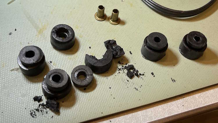
The feet only come with the feet themselves, so you need to punch out the old brass bushings and keep all the hardware. Since I had all 4 feet still, I did that - and the old ones just crumbled to pieces.
New on the right, old on the left. There’s nothing left of the old ones, so they go in the trash.
Installing them is relatively easy. They slide into case slots, and screw into the chassis for the back, and just lock down with screws in the front. That, and the front panel screws, and we’re ready to go.
Next is to do what I set out to do - replace the filters. I need to fix the mistake I made last time, and get the new ones wired in. But, what about all those paper caps, you say. I’m not recapping this thing for daily driver use - there’s simply nothing to listen to and I have a nice long distance AM radio sitting beside me as I type this. This is just to make the thing play.
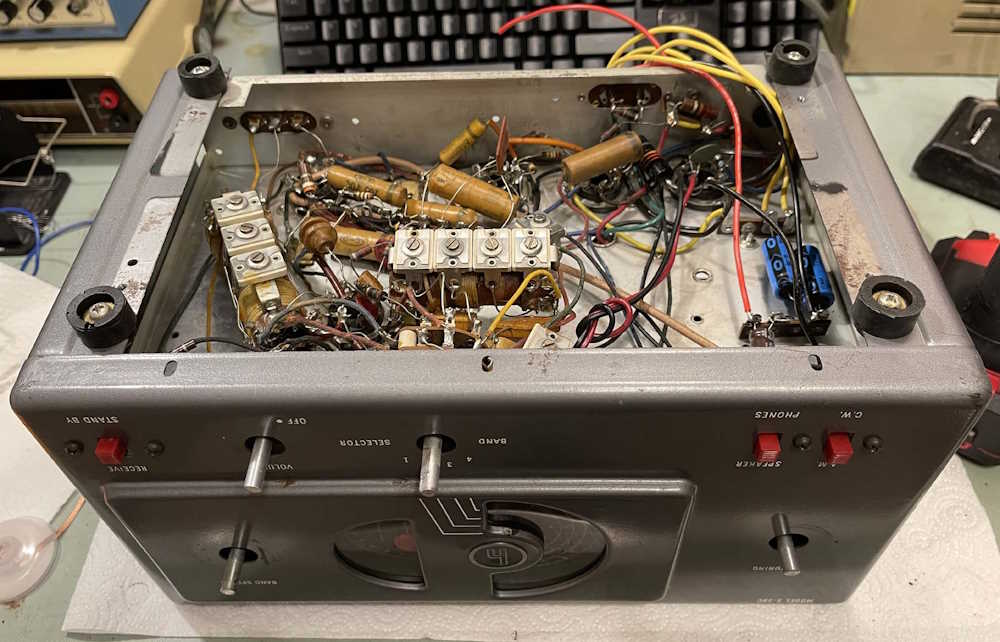
Before I bolted the device back together, I did some quick checks on the unit. B+ is around 600V, no sparks, smoke, or other problems to note visually, the case isn’t live - we’re good to go.
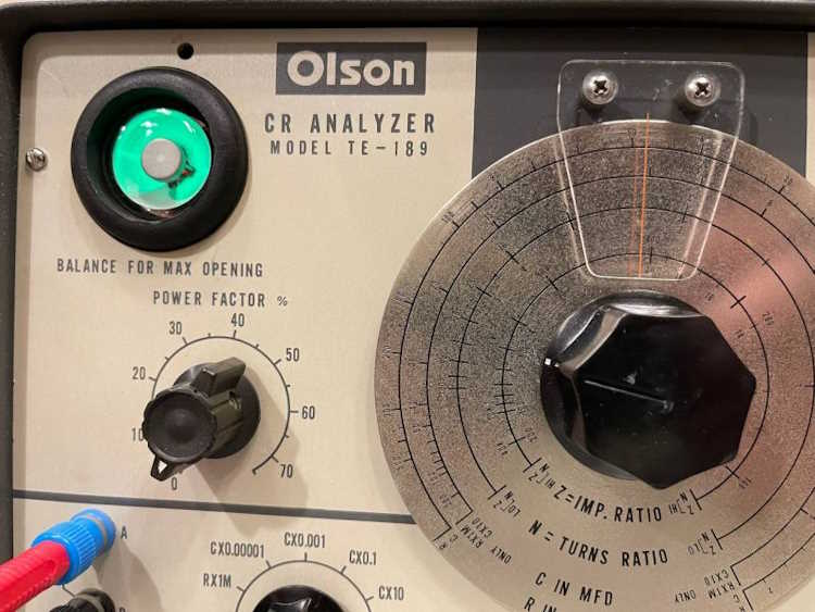
So. Does it work? Well, yes - for a given value of work.
What does that mean? The device seems to work best for capacitors that were commonly being tested when this thing was new. Electrolytics are fine. Mica? No problem. Big old paper foil? Yep, we’re good.
Modern film? Barely. Ceramic? Don’t even try. These devices weren’t designed to test this type of part, and you won’t get any useful results. Some older devices, especially those from Heathkit, actually stated the types of acceptable parts on the front panel and it’s just the three I’ve listed above.
So it’s not really going to replace the $25 component tester you have in your drawer. But it is great for testing those big old electrolytics, and seems to be decently accurate. It’s fine for resistors as well, and again - seems decently accurate. As accurate as a dial and a subjective “eye open” measurement can be.
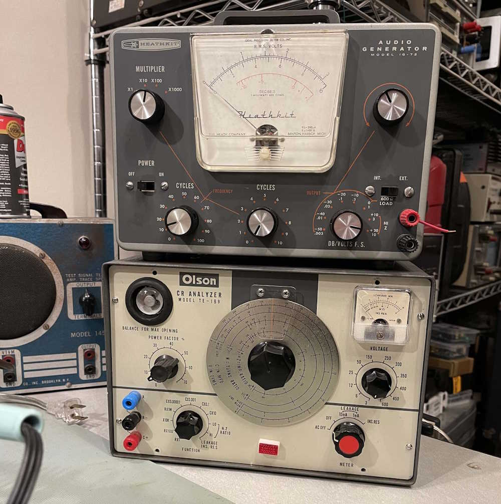
I didn’t bother getting a new handle strap for it. It’s going to sit under the signal generator, so no handle is fine.
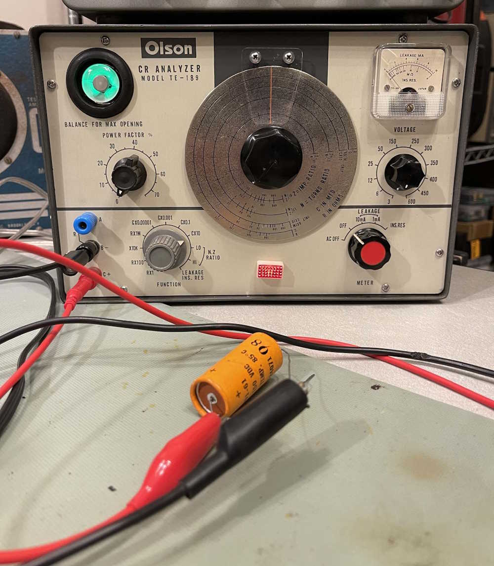
And here’s a bad shot of it testing an old dry electrolytic rated at 50μF - but actually reading 68μF on my good B&K capacitor checker. The dial is about 65ish, and the eye is open. Yep, that’s pretty good for an analog device with resistors that drifted farther out than the asteroid belt.
I’ve played with some other functions, but don’t necessarily know how to use all of them. I need to read the “manual” ha ha and see how to make it all work.
And the schematic diagram for the unit, as good as it is:
These all came from the Dr. Zee workshop page. I did try to contact this person in regards to the information and their rebuild of said device, but never received a reply. I chose to believe my message wound up in spam and the person didn’t see it - but if you’re that person and you want these links removed, please contact me on mastodon.
Mike’s had the neon panel lamps, a lucky chance find. Remington and Science Purchase both sell good quality solid wire, Surplus Sales has all kind of terminal strips, and Just Radios sells all kinds of oddball capacitors and resistors useful in old radio and equipment repair.
Final thoughts.
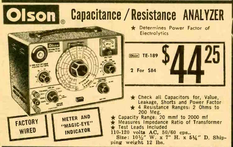
While there really wasn’t much wrong with this device other than the typical stuff you’ll find in an old Japanese device, it’s a prime example of why you do not buy stuff like this sight unseen. This thing was built so poorly that it’s really amazing it even worked. It’s also interesting because I can’t find any mention of these devices being kits - the Olson 1968 catalog says “Factory Wired”:
(That’s $400 today, BTW…)
How did this thing get in such bad shape? I can’t answer that - all of the parts I removed were period correct, so it wasn’t like it had been modified over the years. Couple that with there should be some mention of an assembly manual out there somewhere, but there isn’t.
That’s why you can’t buy something like this without seeing it first. You would be perfectly reasonable to assume this was wired by a competent person in a Japanese factory. I hope it wasn’t for their sake!
Beyond that, it was basically a 1960s Japanese era device rebuild. All of those oil-paper capacitors had to go, and most were replaced with modern equivalents, even if they weren’t exactly the same value. The only one I tried to keep exact was a capacitor in the measurement circuit, and that was made from two in parallel. Others, like the filter, were made from multiple parts as well, and that’s fine. Everything else was wiring and touching up joints.
This device’s condition will forever be a mystery. But then again, buyer beware! Check before you buy.
The complete series on rebuilding this device:
An Olson TE-189 C-R Analyzer - Does it work, and final thoughts. - You’re reading it now!
When I started this project, it was going to be a replace some caps and move on. Well…the unit was such a basket case that it needed a lot more love. So what was replaced?
Almost all of the coated wire. I tried to keep the original colors, even though they meant nothing for the most part.
The power cord.
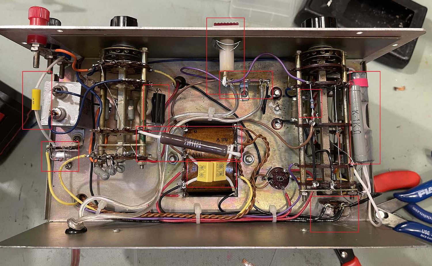
(from left to right)
The input blocking capacitor
The bypass capacitor and a resistor for the eye tube.
The 0.04μF capacitor in the measurement circuit.
The 500Ω balancing resistor,
The two across-the-line capacitors on the transformer.
The neon panel lamp.
The neon panel lamp resistor.
The main DC filter.
The filter capacitor was an unusual 5μF @ 700VDC capacitor. I made one from two 10μF @ 450 units, enclosed in a piece of heat shrink. A red band was placed to indicate positive. I think it turned out ok.
The only thing on the top that was replaced (other than wire) is a resistor for the eye tube, mounted directly on the socket.
Miscellaneous:
Knobs, most of them were stripped out.
Screws for the pointer because they snapped when I took it off for cleaning. I used #4 flathead screws here. They sit slightly lower in the pointer than the originals, which were the size of whatever Olson had on hand at the time.
Screws for the face because they were all missing. I assume these were also some odd size because M2.5 was slightly too small and M3 was slightly too large. I ended up going with M3 and just giving it a little elbow grease.
Screws for the back - no idea what these were, I just found something that worked. I think what I used was duplex screws. Who knows, they were in my parts bin and worked-ish.
This unit has been one of the more interesting devices I’ve picked up at a show. It’s not age related problems, it’s poor build quality from the get go. I think I’ve said it before, but I wonder how this thing got in such a bad state - were these even sold as kits? All of the screws were coated with some odd loctite material, so it appears to have come at least partially assembled…
Regardless, after waiting for the correct wire, I got started again. The wire went on quite the adventure, from Illinois to Ohio, where it visited some suburbs of Columbus. It headed out to Kansas City and visited both states that city occupies before heading to Indianapolis, and finally back to Columbus where it didn’t get delivered. I actually ordered some more wire and got that first - even though the vendor shipped me the wrong gauge! It will still work, however, so onward!
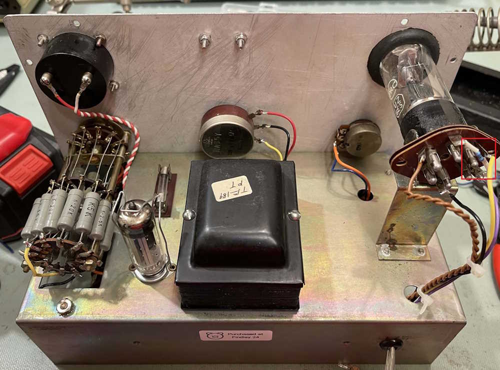
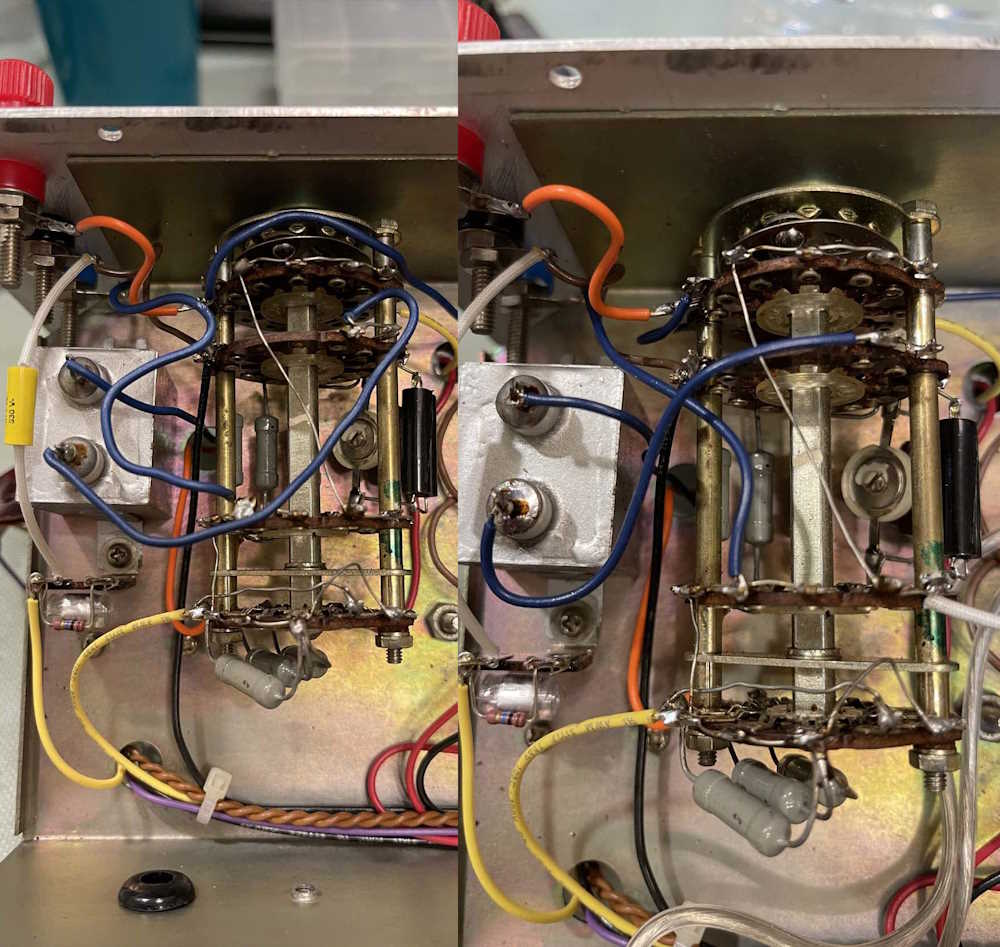
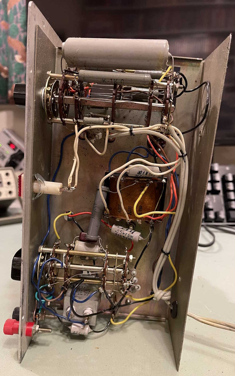
The last portion that really needed rewiring was around the input area:
I did find out that the terminals in that big capacitor are just sitting in little solder pots, so I took the opportunity to clean up a blobby one.
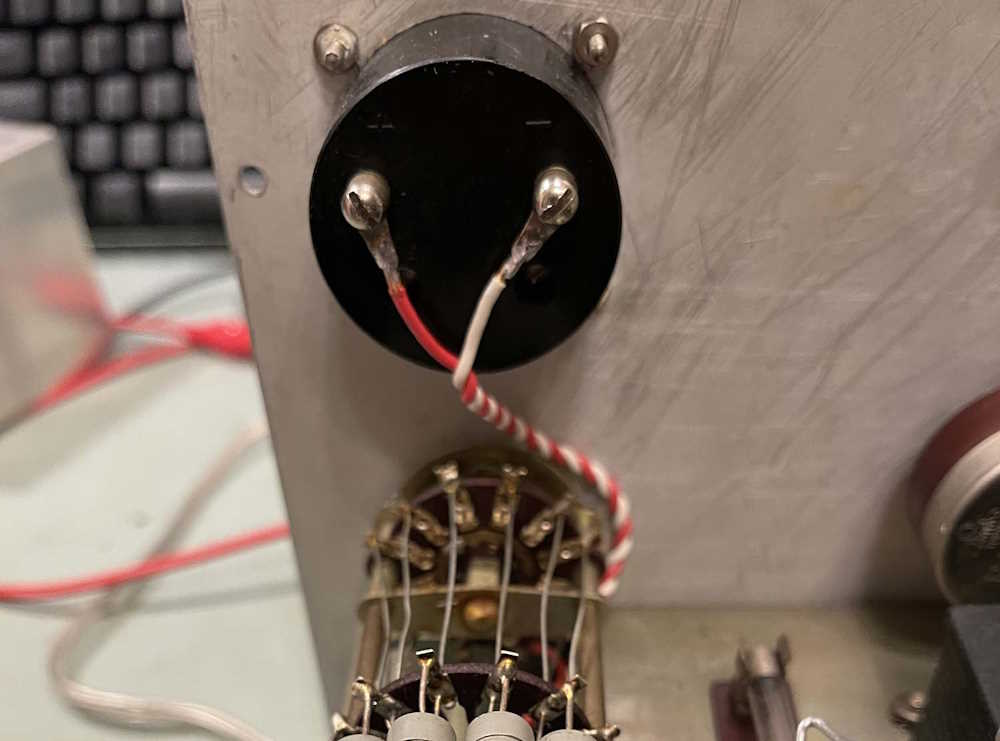
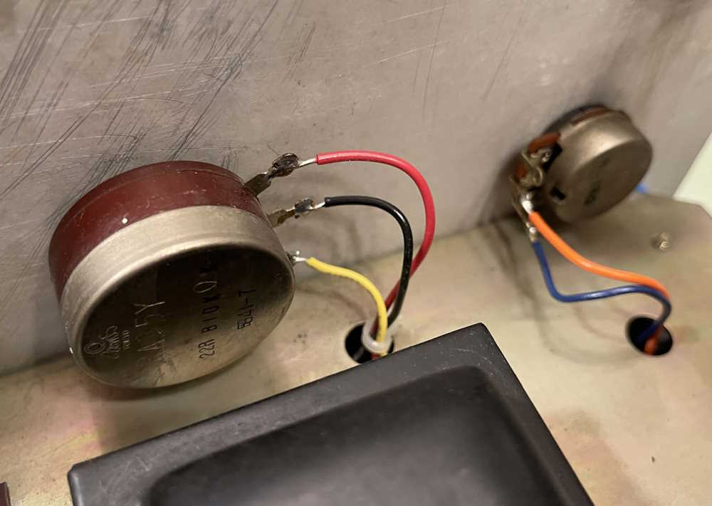
Along the way, I did the meter wiring:
and the potentiometers:
Yeah, I could have done a better job here.
And that’s it. We’re left with a cleaner looking chassis:
and all that’s left is to apply the labels.
A little bit of discussion on what was replaced in the next part, and then for the test. Stay tuned!
Do you buy any vintage equipment online, especially from a certain auction site? While this is probably a foolish thing to do because of the prices - sometimes you can find a very unique piece or a great deal on something you’ve wanted. Sometimes, very rarely sometimes.
However…one of the things I’ve noticed is the descriptions of the items have changed. Most used to be “I don’t know exactly what this is or how to test it. Assuming it’s non-working” or something along those lines. A fair assessment for a non-tech person.
But now, AI is writing things for people and it’s hilarious, but annoying because it’s now more valuable because it’s always “widely used in industry,” “well know for their stability,” or some nonsense. No, it’s a hobbyist piece or something made by a company that went out of business in 1974 because they no longer competed on the market.
There’s some serious SNAD material here, and if a dishonest person wanted to get stuff it would be easy enough to do as eBay seems to prefer the buyer’s word over the seller.
But when an unsuspecting buyer thinks they’re getting a device that does digital QAM/Digital Video because the seller just AI wrote some garbage and all they receive is an ancient Leader audio generator that wasn’t great when new - someone isn’t going to like the results.
If you’re selling something and you have no idea what it is, ask a friend. If you don’t have a friend, do 5 minutes of research and find out what it is. Copy the manufacturer’s boilerplate if you need to.
Just don’t tell AI “Write me a description of a Doo-More Signal Generator so I can sell it.” You’re going to get trash, and possibly a strike on your sales.
As we say goodbye to 2024, I took a look at the shows I attended - there were quite a few of them this year, and it surprises me how many of them are in Ohio and the surrounding area. Had time allowed, I could have attended more, but one a month (or thereabouts) is a good schedule. To wrap the year up, here’s a link to all of the pictures from these shows.
I’m looking forward to the coming year’s schedule - you can find that here.
The December Scott Antique Market is happening this weekend at the Columbus (Ohio) State Fairgrounds / Expo Center. This is the last show I attend for the year, and I’ll have pictures and a year-end wrapup shortly after.
This show usually has a lot of #radio and other antique electrical and related goods, as well as your standard selection of antiques and other related merchandise. Doors usually open at 9AM on Saturday, but always check before you go.
Admission to the show is free, but the expo charges parking per car.
Scott Antique Market - December
Ohio Expo Center (State Fairgrounds)
717 E 17th Ave
Columbus, OH 43211
December 21 and 22
Hours vary by day, check before you go.