I’ve posted a number of manuals and things over the past few years, and they’re scattered around the site. Here’s all of them to date, this list will be updated as new ones are added.
Since this was originally posted, I’ve added a document share to this site that contains everything that I post about (and have a document for.) Find it here: https://wereboar.com … r=wereboar-documents
For the most part, the OX Drive documents have been removed.
Please share, but let them know where you found it. Come visit this little pig!
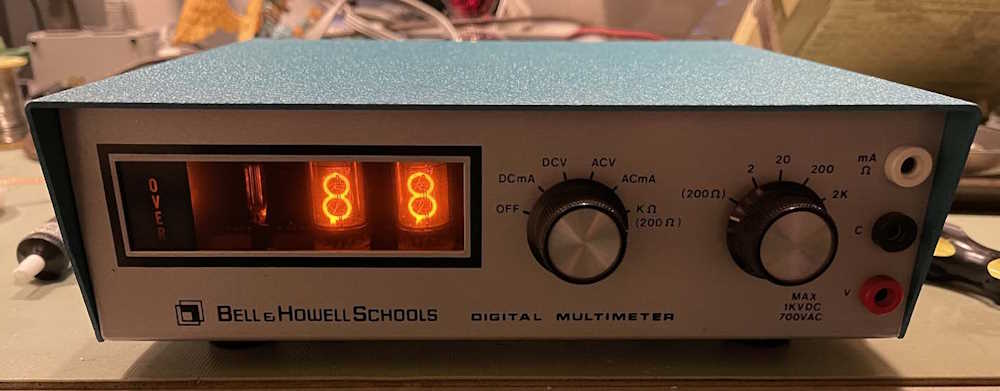
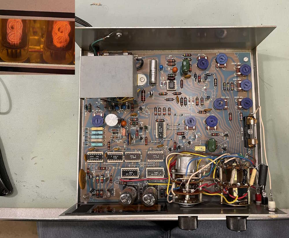
SO…here’s another one of these piece of crap meters. Why? This one was cheap, and was purchased non-working - primarily for parts, as in the NIXIE tubes. ZM1000 tubes aren’t exactly common these days, so having a few spares laying around seems to be a good idea.
I decided to at least take a look inside to see what’s broken. It doesn’t power up because the fuse is blown. That never bodes well, so I jumpered the fuse temporarily and turned it on quickly.
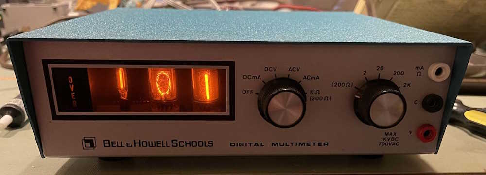
Yep, it’s got some problems. All segments of the tubes are lit, and the tab on the +5 regulator transistor got pretty warm being on for 5 seconds. Turned it on again to get some quick voltage measurements:
+5V Output (Emitter) = +0.8V
+6V (Base) = +2.6V
Measuring the resistance to ground:
E = 2.8 Ohms.
That’s not good.
A good unit measures (to ground):
E = 1.4MOhms.
+5 primarily powers chips, so I pulled all the ICs to start. Things changed, but not necessarily completely back to normal.
Good unit:
E = 1.4M
B = > 8.5k (charging)
C = Open
Bad unit:
E = 2.5k
B = 1.9k
C = Open
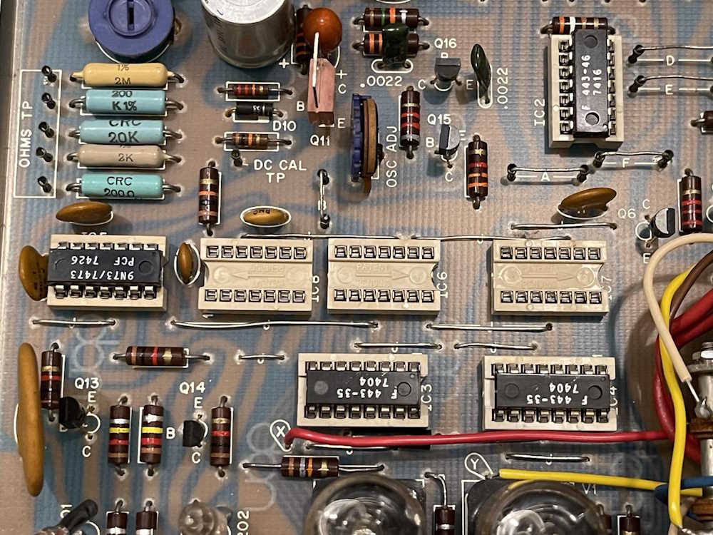
I started putting chips back in, the very first one I replaced (IC5) took the Emitter of the regulator transistor down to 3 Ohms. So that chip is bad.
However, there’s something else wrong. With all the chips gone, the +5 load should be negligible. I did a quick scrape on the transistors to see if one was shorted but didn’t find anything obvious. That leaves old capacitors that could be leaky. This thing is full of Tantalum drops and cheap-ass film caps, any one of those could be partially shorted and there’s no real way to know except to start lifting parts.
Since this is just a parts unit, and the tubes and driver ICs appear good, I think it’s just going in the parts bin as intended. Maybe if I have some snowy Saturday, I’ll pull it out and start lifting parts to see what’s going on. But for now - parts is parts, and parts is what it is.
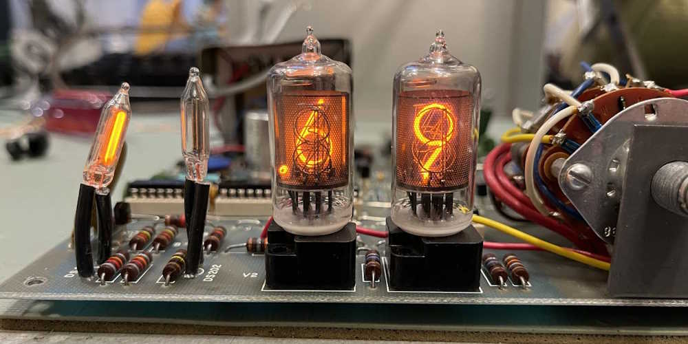
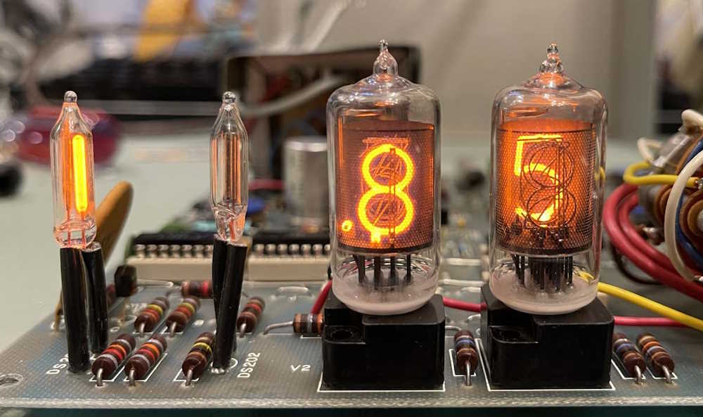
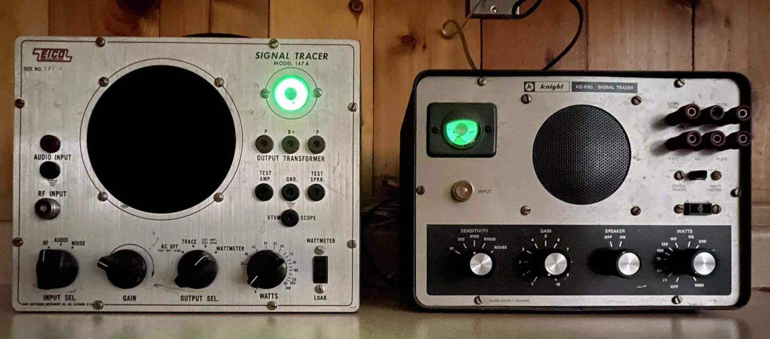
One of the most interesting and accessible pieces of tech that came out of the tube era is the Magic Eye. A phosphor cup (or target) is illuminated with an electron beam, and a grid allows or blocks that electron beam to “open” the eye. It’s a device that can indicate changes at the speed of the phosphors used, and it found it’s way into all kinds of devices - radios as tuning meters, signal tracers as signal indicators, capacitance checkers as a quality meter - anywhere a fast visual change needed to be shown to the user.
These two signal tracers, one branded Knight, the other Eico, have eye tubes as their wattmeter and signal indicators. The Eico’s eye is so bright it overloads the camera, while the Knight’s eye shows much more use in it’s dimness.
While eyes fell out of favor as meters, VFDs, and other electronic indicators came into their own, they still remain one of the most striking devices in mid-century electronics.
It’s a Switchcraft 2501f Microphone Connector. It found it’s way into low-frequency RF devices after WWII, where it remained until displaced by the superior BNC connector.
They’re still available, but they are not cheap - expect to pay $14-15 for a new one! If you’re not worried about looks, just replace it with a BNC and be done with it, you get access to a wider range of connections.
I’d never attended this show, but was pleasantly pleased with the turnout. There were perhaps a few dozen vendors and a packed house of visitors in the old gymnasium of the converted school. Quite a bit to look at, and prices were really good. I managed to bring home some good things for a total of $10, almost spending more on drinks and snacks on the way home! I didn’t think the weather was going to cooperate, but it turned out to be just a bit slushy, cold, and windy.
We wandered the aisles for about an hour, taking some time to stop and look at the old photos on the walls from the building’s time as a school, talking to some of the vendors, and digging through boxes of stuff. Since this is so close and easy to get to, I’ll probably attend next year as well - weather permitting of course!
A bunch of books. The ECG manual went home with a friend.
Some rat shack remainders. I picked up the cable.
Lots of AM CB showing up right now, including these old phone-style units.
Parts, and some rat shack 300 ohm clip on connectors. Got these for the nostolgia factor.
A friend pulls a microcassette unit from a dollar bin.
Some test equipment. The (working) signal tracer went home for $2.
More random equipment.
Even more equipment. The power supply was unique enough to go home with me for $2.
And I have to say it was a pretty good little show. The weather wasn’t planning on agreeing on the ride down, but it turned out to be just a skiff of snow and cold, windy weather. There were maybe a couple dozen vendors, and a packed house full of guests to the point where cars had to shuffle so others could leave.
While I only spent an hour there, I walked out with some good stuff as did my fellow show-goer. I’m working on processing pictures, and will post those soon.
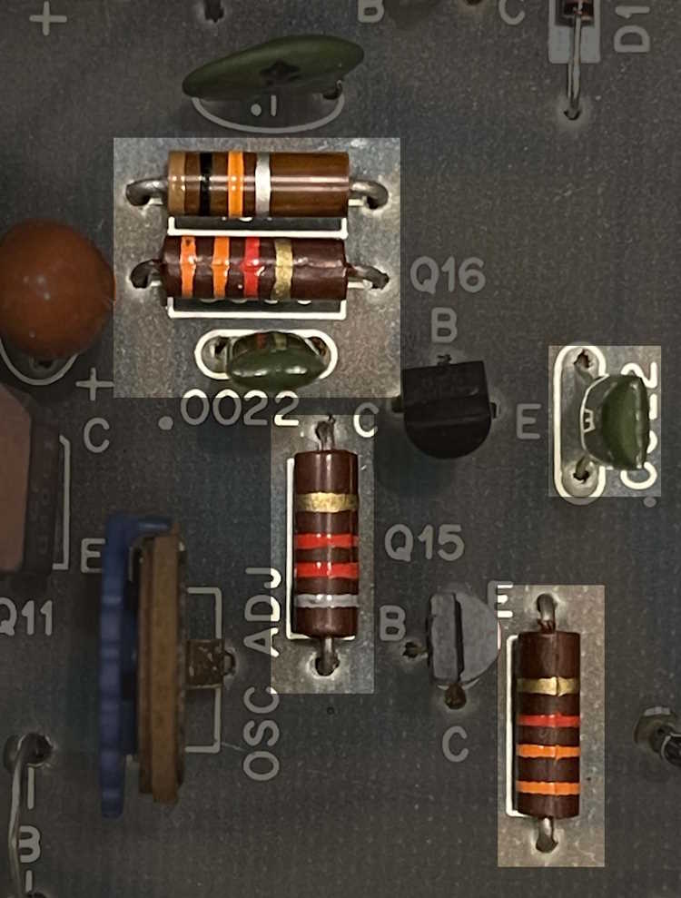
One of the issues with the IM-1212 and it’s clones is that it drifts all over the place, and part of that is the oscillator that actually does the counting for the display. This is an attempt to replace that section with better parts to see if it’s any more stable. I started this with this previous post, and present my findings here.
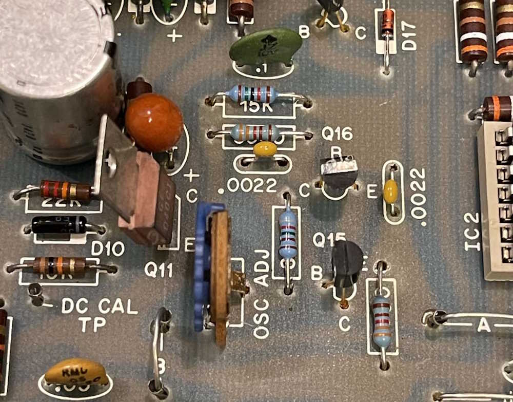
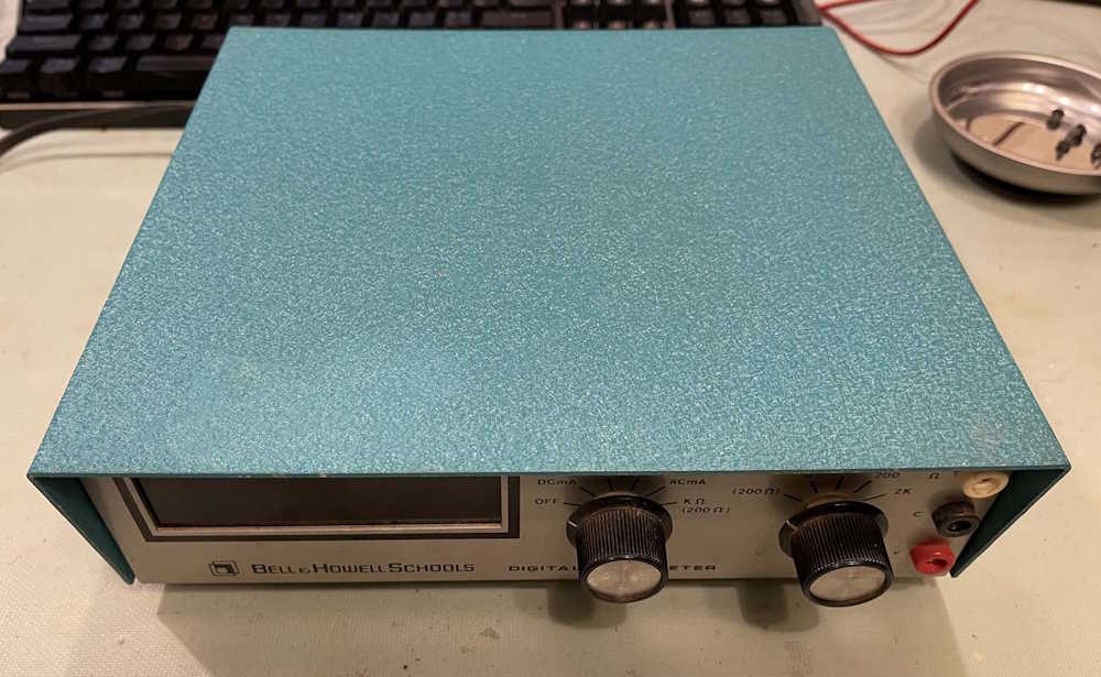
We start by identifying the components of interest and removing the board:
In the oscillator circuit, other than the transistors, are the following passives:
We’re not going to replace the pot, but all of the other components are going to be replaced by film and/or temperature stable to 25ppm components.
The sharper-eyed among you will have already seen an issue. There’s no 15k resistor identified here, and I’ll talk about this a bit later in the process.
Before taking the board out, I let it warm up and preset the oscillator to it’s suggested 85 count.
Getting the board out isn’t too bad. There are 6 screws, three solders, and a clamp.
The screws are the ground lug for the power cord on the back panel, the two screws that hold the transformer down, and one screw each in the remaining corners. One of the screws is under the switch assembly and can just be seen by the red input jack, so you’ll need something relatively thin and long for this one. They all appear to be the same size.
Next are the three jacks on the input. I unsoldered these at the front panel itself, but the white wire was long and flopped around and broke because it is solid wire. Not a big deal there.
Last, is the clamp for the power cord on the back panel. This is just squeeze it with pliers and work it out. I left the power cord attached to the unit and just pulled it through the bottom case so I had enough room to work, and used the ground lug screw and nut to temporarily hold the transformer down as not to break the relatively fragile connections to the PCB.
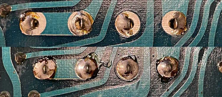
Before getting started, I did an inspection of the board. There were a number of bad solders on some of the components - mostly things with thick leads like the potentiometers. I took a minute to clean those up before getting started.
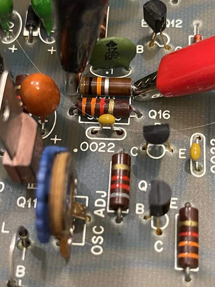
Removing the parts is relatively easy, this being a single sided board. A soldapult and some wick made short work of the old solder, and that’s when I noticed the 15k resistor wasn’t.
The schematic indicates 15k, as does the board - and another unit I have has the correct 15k part in it. I have to wonder why this was there - did the original builder not get the correct part, or was it broken during assembly? Who knows - but it didn’t really matter as the device worked.
Interesting.
The rest of the parts are replaced without issue, and the correct 15k is placed where indicated.
There’s not a lot of current or voltage here, so I wasn’t particularly concerned with the size of the resistors.
After doing a precursory check of parts, solders, and whatnot, I powered the device up on the bench. The oscillator count was quite different, so my replacements had some effect.
Some warmup time later and I adjusted the oscillator to the correct value:
Putting it back together and:
It’s already drifting. I set it back to 85 and let it set until the next day.
It didn’t do a thing. I will say, however, that it seems easier to adjust it back - there’s not as much play in the overall adjustment - you can set it and it generally stays there until the temperature changes.
So, my conclusions? This whole thing probably would need rebuilt with modern components in order to maintain any stability in measurement. For now, it’s just going to be sitting in a rack on all the time measuring the 12V rail of a power supply so … it is what it is, I guess.
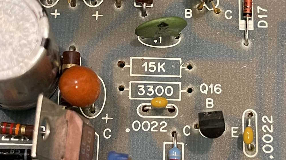
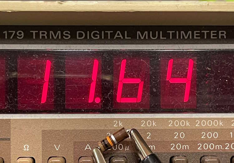
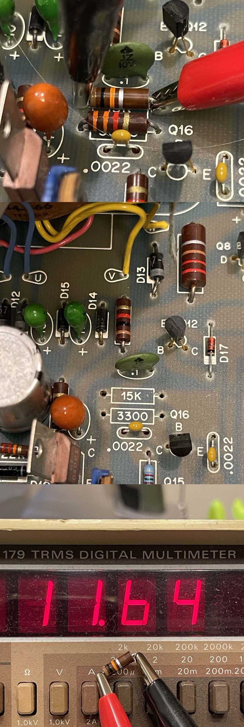
2024 brings this device from years ago, which I opened to find a mistake in assembly. This Bell & Howell IMD-202-2 NIXIE meter has a 10k resistor in the oscillator circuit, where the board and schematic specified a 15k.
The carbon resistor used was so sloppy that it didn’t really matter what went in there, of course, as long as it was close enough to the value specified. The part had long since drifted out of tolerance, the upper limit being 11k - this one read 11.64k!
I have to wonder if the person building this kit did that accidentally, or on purpose because they didn’t have the correct part, or maybe they chose it to correct something else. I’ll never know, but a 15k precision went in to the circuit and seems to be working without issue. I have to assume it was simply an honest mistake, as I didn’t see any evidence of rework on the bottom of the board.
Stay tuned for my findings on trying to fix some of this device’s drift.


 signal tracer went home for $2.")