An Eico 145 Signal Tracer - Part 8 - And, we’re done.
Monday, October 21, 2024 at 06:19:41
This is the last part of the Eico 145 rebuild series. I’ll have one more post in regards to this unit, but that will be a wrap up and general thoughts on the rebuild process.
As in the previous post, I found a couple of mistakes in my work during the final check Those were corrected easily enough by adding a wire from the B+ point to the junction of R3/R4, and changing the 510k back to a 10M resistor. It turned out I did have the 10M resistors, and had ordered them.
I think what happened here is because I didn’t like the lay of the first part I used, I pulled it out. I didn’t pay attention and just grabbed a 510K because I saw the blue stripe. I’ll lay some blame on the blurry schematic, but most of the fault here lies with me. That’s why I checked my work.
The B+ line was a simple oversight. I remember running the rest of the B+ circuit and, because I had too many wires on one connection point, thinking to myself that I need to find a second tie point for the rest of the voltage. I didn’t do that. Again…checking your work is important. No matter how long you’ve done this kind of work, check it when you’re done.
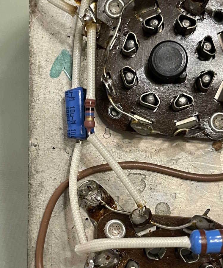
The new 10M resistor gave me a chance to lay it in nicely.
I did put some other resistors in there for testing before I remembered the parts I bought specifically for this unit, specifically these two 4.7M carbon comp resistors that I just stuck out the side. Parts layout is important, as this gave a lot of hum:
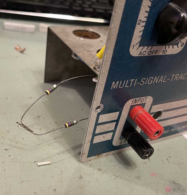
Don’t do this. It made for a lot of noise, and it just reinforced the need for keeping your layout clean. Keep stuff short and close to the chassis. It did prove to me the device worked, however.
With that being said, all parts are placed.
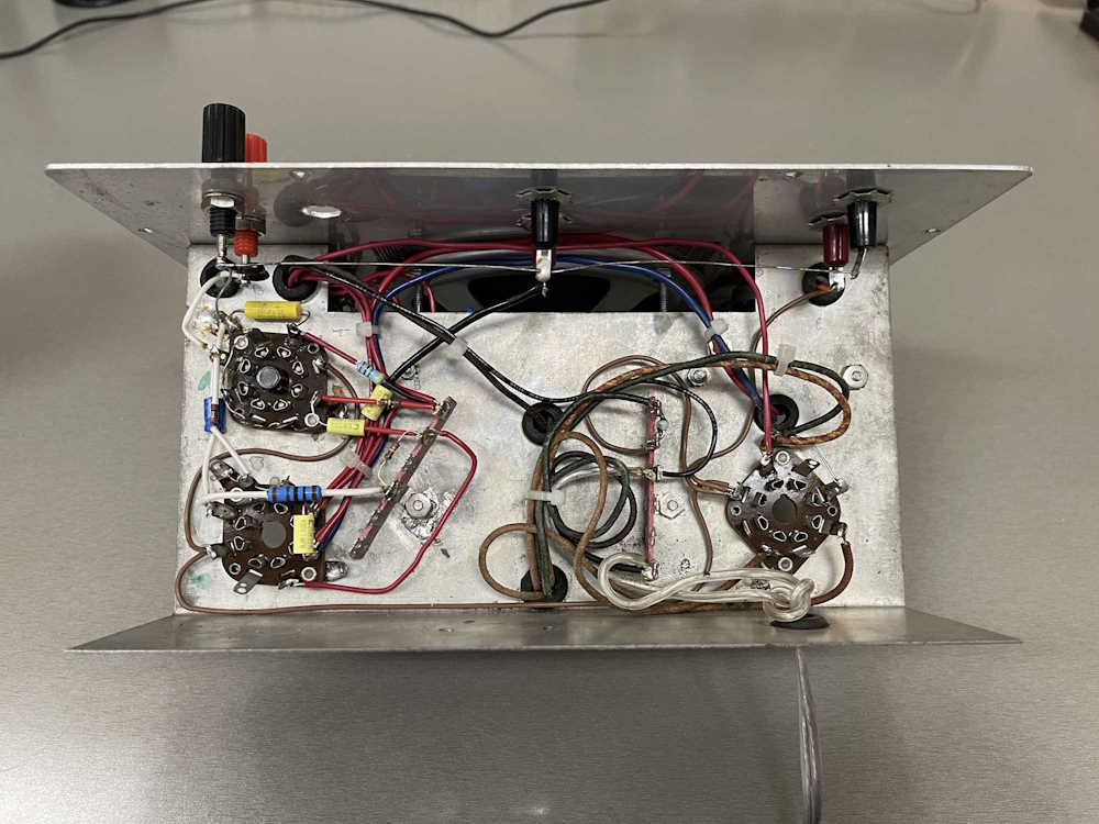
I’m still not completely happy with the layout, but everything is soldered and tight. It’s not going anywhere.
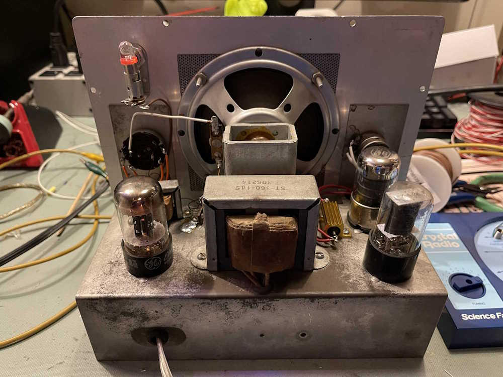
Everything powered up with no issues. You can’t really see it as these devices don’t have much glow, but the rectifier on the left side has that tell-tale orange of the heater.

Put some labels on the back for posterity, and…
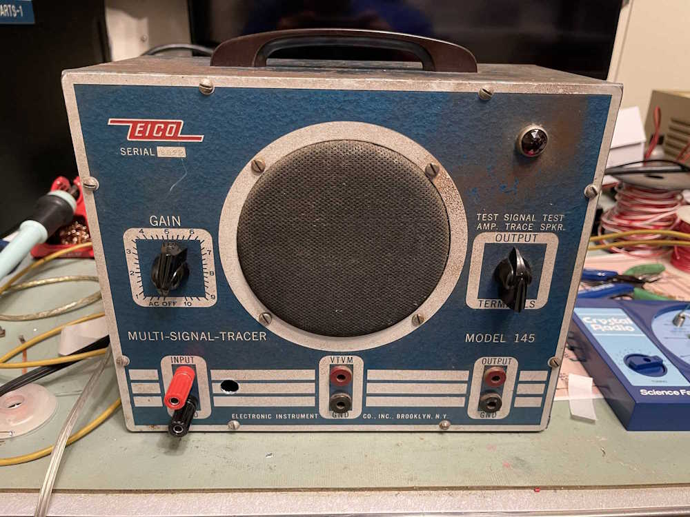
And it’s all done.
It still has some minor hum, but nothing like the whine it had with the 10M hanging out the side, and it’s a bit quieter than when I got it. I’m happy with the results, and I spent 10 minutes or so listening to some talking head on the crystal radio drone on about some topic that’s going to destroy everything or something, I don’t know.
There’s one more not-part of this series on the way where I wrap up thoughts and provide some things I’ve learned on the way to this point. Stay tuned, that should be ready to go later this week. That post will have links to all of the posts so you can easily start from wherever you like and read from there.
Stay tuned!
Final part of this series: https://wereboar.com … -and-final-thoughts/
Previous part of this series: https://wereboar.com … -checking-your-work/