- 2024
- Oct
- 28
A Heathkit IG-72 Signal Generator Part 4 - Final - No need for repairs.
This is probably one of the easiest devices I’ve had to fix - there was really nothing wrong with it beyond needing a new power cord and a tuneup.
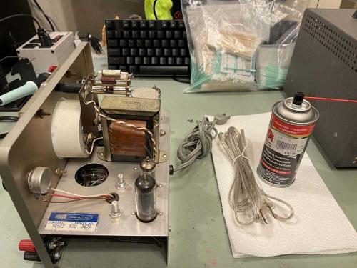
A tuneup, in this case, consisted of some Deoxit in the controls, and a new power cord:
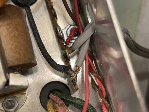
There are three reasons I’m replacing the power cord. First is the fact that the old one is about that close to being hard plastic. Since I have it open, it may as well get a new one. Second, I can replace it with a polarized device. This isn’t a hot-chassis set, but I’d rather have the hot on a switch. Third, this just doesn’t look good to me:
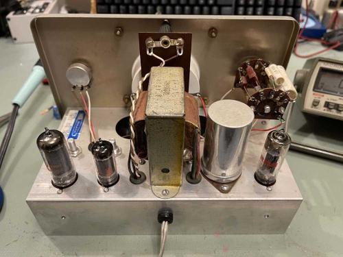
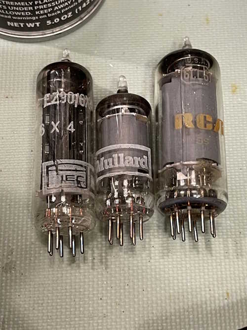
I’m also going to replace the tubes. The old ones aren’t bad, but I bought new ones, just in case. There’s no need to not use them, and the old ones will go in the boxes as spares. I’ll probably pick up another new set, but I can’t imagine these will go bad in my lifetime.
You can also see the new power cord exiting the back of the chassis.
There were two of the original Mullard tubes, and one RCA. The getter flash on the RCA tube looks a little baked compared to the new one, which is a nice, shiny RCA device.
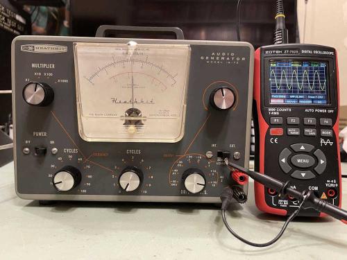
In order to calibrate this, I basically ignored the manual. Since we have DVMs with more than 500 ohms/volt impedance, we can calibrate the device directly. Take note, however, that the device needs to be good and hot before doing this. Let it warm up for a long time to stabilize. I’d suggest taking it out of the case and putting a cardboard box over it. Also note this device was designed to run on 110VAC, so you may need to variac it down a bit.
But, to start, I did a quick beginning cal on it. I set the frequency to 1Khz, and attenuators to minimum. A scope was connected, as was a digital meter. Frequency was set to 1KHz, course attenuator (switch) and fine attenuator (pot) to minimum. Meter and Oscillator controls were set to about the middle of their range.
You’re going to adjust the osc and meter controls on the chassis. Oscillator is the one closest to the transformer, and mine had a slot in the top. Meter was closest to the edge, and has no slot on mine.
Power was applied and the tubes warmed up. I turned the course attenuator to maximum, and adjusted fine to about 2/5 of max. The unit wasn’t oscillating well, so I turned the oscillator control CCW until I got a sine. I adjusted this until the bottom wasn’t clipped, and then turned it down a bit more.
For the meter, I adjusted the fine control until my digital meter read ~5.0V, and then adjusted the meter control on the chassis until the analog meter agreed. It’s not a terribly linear meter, so don’t be surprised if it’s off some at other points on the reading.
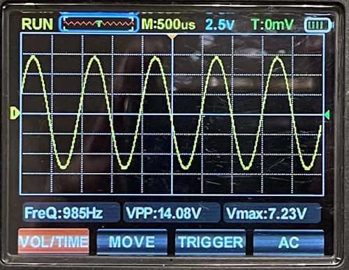
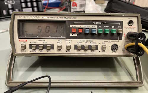
I did notice the signal levels drifted as it warmed up - therefore, let it warm up before adjusting.
I didn’t notice the load switch doing anything. Normally, you would calibrate at load, but I’m not sure why this didn’t do much. I’m not terribly worried about it, the thing makes audio and it’s close enough for what I need to do.
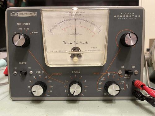
So…that’s it! I’m going to get a box and cover it this weekend while on, let it get nice and hot, and do a calibration - but the device is working with little to no effort.
I have an RF generator to accompany this, I think that may be the next project. Stay tuned!
(Something went wrong during final cal…looks like we do have a problem!)
Next part of this series: https://wereboar.com … 5-were-not-done-yet/
Previous part of this series: https://wereboar.com … t-3-do-i-need-parts/
