- 2024
- Nov
- 8
An Olson TE-198 C-R Analyzer Part 2 - What should we replace?
(This is a TE-189…oops!)
The short answer is everything here that needs to work seems to be working. The long answer is probably all of the capacitors that are in the circuit, the power cord, and the neon pilot (because who doesn’t want the nice neon glow?)
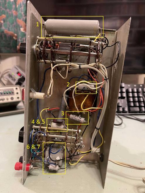
Looking at the unit, there are several capacitors - but not as many as you think - in this thing:
#1 is the big one - this is a 5μF at 700V filter capacitor. Is there really a need for something with this kind of rating in this circuit? You bet:

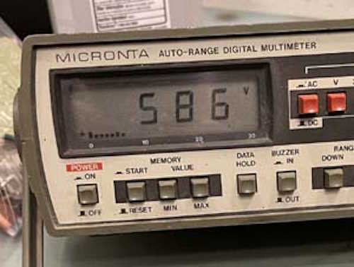
Almost 600VDC is present on this device, so it’s certainly a good candidate for replacement. The OEM left some overhead there, so it’s not completely shot at this point. I have to wonder how this device ever worked, however - the negative lead on the capacitor wasn’t soldered very well and didn’t wet. It just slid up and down on the ground wire.
It’s not the easiest to get something like this in a modern part, so two 10μF @ 450V in series would make an equivalent replacement of 5μF @ 900V. Fine for this thing.
#2 and #3 are “Across the line” capacitors. One goes across the AC line, the other on the tube filament line. These are 0.05μF at 500V. One of them doesn’t need to be that high, but both could comfortably be replaced with 0.047μF at 630V devices that I keep in stock for that very purpose.
#4 and #5 are part of the measurement circuit. 4 is a mica of unknown value, and is the deep red part tucked behind the dogbone resistor. It’s interesting in that it has a ceramic trimmer (you can’t really see it) in parallel. I cant imagine this was the OEM setup, but perhaps it was. #5 is a simple .04μF capacitor. I can’t see the voltage on this one because it’s so tightly packed into the switch. Since 0.04 isn’t really a modern value, parts chosen from a bag of cheap 0.022 parts could probably make a cap that’s closer in value to the original.
#6 is a DC blocking capacitor. Nothing special here, a 0.01μF at 630V - or just about anything close - will work. It feeds the grid on the eye tube.
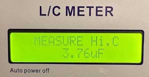
#7 is the odd man out. This is a 4μF at 100WVDC - nothing special you’d think, but it’s in a metal case, almost like a motor capacitor. I’m not sure what the significance of this style of part is. Perhaps it’s a low ESR or has special power factor qualities? It is in the power factor test circuit that gets adjusted on the front panel. More research is in order here, but the part reads 3.76μF in circuit. Assuming it’s a 10% part, it’s still in tolerance. The schematic I have doesn’t say, so…who knows. In another rebuild I saw, this one didn’t get replaced. (no, it’s 2%…odd!)

There’s one more part hiding here, a 1500pF used as a bypass on the grid of the eye tube. It’s hidden on a terminal strip beside parts 6 and 7 - it’s a tiny ceramic disc, so it’s probably been replaced at some point. It’s so packed in there I don’t know what the value is, but that’s easy to get and I’m not worried about it.
The resistors and other parts all seem to check out ok, so the capacitors will probably be it (other than a good cleaning.) I’m not trying to get the device working by replacing these, as it already works, so this is just safety maintenance. Next is to find parts and order them - stay tuned!
Next part of this series: https://wereboar.com … some-notes-on-parts/
Previous part of this series: https://wereboar.com … te-198-c-r-analyzer/
