- 2024
- Dec
- 1
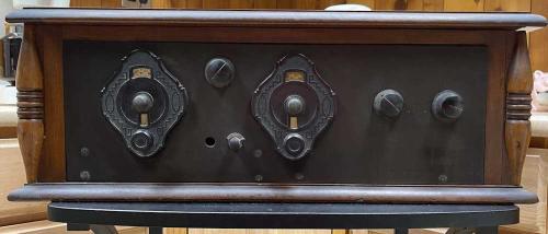
An Unknown 2-dial TRF radio.
The Scott Antique Market happened this weekend, and much to our (and a lot of other people’s surprise!) it opened an hour later at 9AM. Remember what I said about checking hours? Well…guess what this stupid little pig didn’t do?
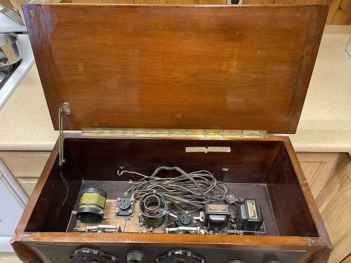
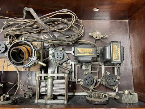
(Some update notes on this - it could be a regen unit as well, according to some. The little glass part marked “GLASTOR” may be a grid-leak resistor, aka GLASs resisTOR. And, there are no parts under the wooden plate. What you see is what you get!)
Anyway, there was some good stuff to see, but I didn’t really see anything I wanted to bring home until we were getting ready to head out. My show-going companion stopped by a big coffin set on a table. The guy had a price on it and I was going “That’s a good price for that piece.” I ended up buying a box of tubes he had beside it, but my buddy was stuck on the radio set itself. I looked, hmmm’d…do I have room for this thing. The guy said “If you want this, how about this other, lower price.” Buddy was just looking at me with puppy dog eyes saying get this dude. So I did.
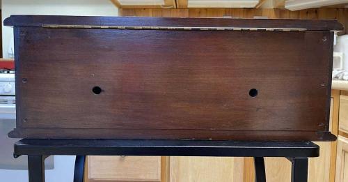
It’s obviously a homebrew set. The empty hole doesn’t look like anything was ever in it. The parts inside look like it was a partial kit, or at least contains parts that allowed you to make your own layout.
Two tuning capacitors, a couple of rheostats, and an on-off switch adorn the front.
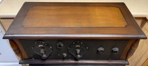
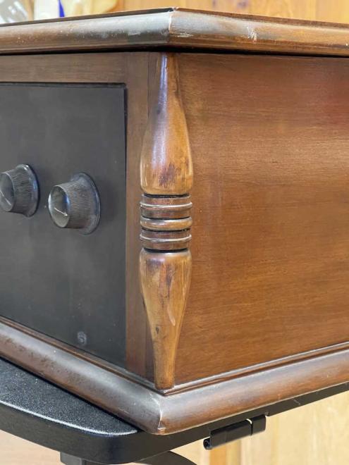
The cabinet itself is pretty good outside. A little scuff here and there and some paint splatter - but considering this thing is probably nearing 100 years old, it’s a solid external 7/10. Inside is very clean, and probably resembles the day it was built. There’s some cloth loss on the wiring, of course, but that’s acceptable and understandable. Some things will need to be tightened up - the escutcheon dials are loose - but nothing major.
Similarly, the rest of the case is in good condition. The varnish on the top is really the only bad spot on the unit.
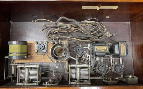
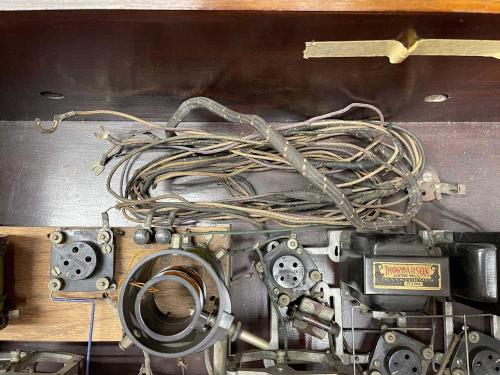
As for the inside…it’s your standard TRF layout. Two tuning capacitors and a tuned inductor present themselves immediately. I’m not really that familiar with TRF sets, so I’m not going to go any further with that in trying to define what they all do. Four tubes, and two interstage Thordarson R200 transformers are really all that’s in this thing. I’m assuming there are some parts underneath the wood plate, but I have not dug that far into the unit.

I’m going to assume this needs +90, +22.5, +5, and +1.5, and that they went in the spot where the cables currently reside.
As for the tubes, all of them were present but wrapped in paper, so I don’t know where they go.
Tube compliment for this is 3x UX201A and 1UX200A. The 201’s are all RCA branded, and one has a Western Auto Supply price tag of $5.00 on it - that’s nearly $91 today! The final UX200A is unbranded on the base, but has a “Wizard” sticker on it. It’s also priced at $5.00 at Western Auto - so there’s nearly $400 in tubes in this thing!
The 200A dates this to at least 1926 and no earlier, as that device was introduced in May 1926. It’s possible the unit is older, but I can’t see someone discarding such an expensive tube just because a slightly better model was announced (although it’s possible.) Since superheterodyne was already a thing at the time, it’s probably not much newer than ‘26 as TRF was a rather poor (although easy) way of getting audio from the air.
The paper the tubes was wrapped in is a Columbus (Ohio) Dispatch from 1970, so the previous owner set it aside some 40 years after it was turned on. The paper itself is quite interesting - a story about how banks are cutting back on loans, a story about how federal payrolls are ballooning, and an ad for credit card fraud monitoring and restoration. You could almost change the date and reprint this thing!
Regardless, this was a great deal and I’m happy I brought it home. As stated earlier, TRF is really outside my knowledge range, so my next step is to grab a few early radio books that have TRF circuits in them. It’s quite likely that the original builder followed a schematic in a book or magazine, so finding something similar probably won’t be too difficult.
If you recognize the layout please let me know on Mastodon or LinkedIn, and stay tuned!
Next part of this series: https://wereboar.com … fying-things-inside/
