If you don’t, geocities was an early “personal web space” host that allowed you to create a simple page. They ranged from fan sites to personal ramblings, with some information and everything else in-between. I collected a lot of useful things off those pages, including stuff like pre-made plugins for software, links to companies of interest, and images of otherwise unobtainable things.
These sites were more often than not characterized by garish backgrounds, flashy things, more fonts than you knew existed, sound and music blaring out of your speakers, and all of the Under Construction GIFs that your machine could possibly handle without melting your video card.
I used mine as a holder for links that I could hit with my BlackBerry, among other things.
But, in 2009, Yahoo! decided they wanted to discontinue the service - 10s of thousands of web pages, full of information from the old internet, would suddenly vanish - and it would have if not for the efforts of companies like geocities.ws, among others. There were many projects to collect as much of this data as possible. Personally, I think Yahoo! really did a big F*** YOU to the internet by not handing over the archives - or at least keeping it static. It’s not like their draconian TOS didn’t give them the right to do whatever they wanted with your data.
Regardless, I found my site in the .ws archives and claimed it by having them send email to the (at the time) existing yahoo address of the same name. It’s been a few things over the years, but right now it’s a quick-link to this place, with a few preview images.
While there’s nothing on that site you haven’t seen before if you’ve been browsing the wereboar pages, it’s still there just in case. Why not, it’s a small free space to host something. If you had a geocities webpage at some point, there’s a chance it in the geocities.ws archive. If you have some way of claiming it, like the yahoo address associated with it, you may as well do so. Time to relive the old internet, party like it’s 1999, and use at much comic sans as you can!
(no epilepsy inducing flashing images or synth-pop that blows your speakers out, I promise - and I won’t even open your CD tray.)
I wonder if I should put a hit counter on it?
If you’d like a copy of the entire archive as retrieved by ArchiveTeam as the place was shutting down, you can find it on that site by the bay…the one where the skull and crossbones fly. Search for “Geocities” and select the one that claims it’s patched - the other one has issues and won’t complete. The files are fairly well looked after, so you shouldn’t have any issues retrieving it. It’s almost 700GB, so make sure you have room for it, and the 1TB of uncompressed data.
I took a lot of pictures at the show this year. The individual exhibitors had mostly pulled out by the time I arrived, but the museum’s displays were all up and running in their greasy glory. I haven’t had time to fully process the images for display here, but they’re on the way.
I picked one of these guys up at Dayton for $20, modified to work in the 2M band. Figured, hey! I’ll pick up some parts units.
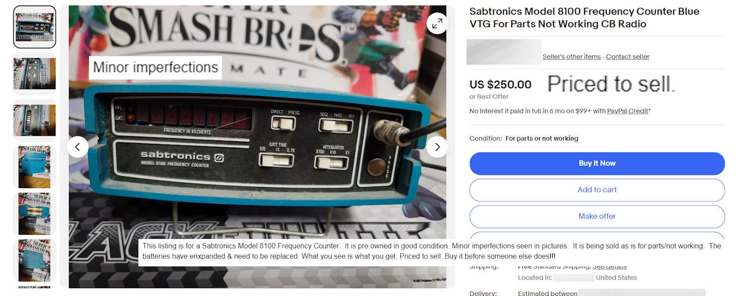
For some reason, a non-working device with a (hopefully intact) broken display cover, swollen batteries (and quite possibly corroded inside,) no battery cover, no (oddball) power adapter, and covered with dirt for $250 doesn’t inspire me to add “Priced to sell” in the description. Especially when the device has been superseded many times over with modern equipment at lower prices.
Hosting for pygg.xyz, as well as email and SSL services, have expired. I’ve set permanent redirects so that any pygg.xyz link should send you to the wereboar.com page of the same name if it exists, or the top level of Projects if you’ve not asked for anything special. There may be a couple of (very old) broken links, but those will take you to the blog’s 404 page with information on how to find what you want to see.
Those redirects may not always work, I’m investigating that but I don’t see any immediate resolution.
I used to host this blog on pygg.xyz, but rapidly found out that .xyz domains have little trust in the Internet world. This affected both my ability to present things to you, and send email reliably using that domain.
Last year, I decided to see what was available - and for some reason, wereboar.com - a very old domain - was available. The former owners, a web design shop and later, some sort of graphics design shop, had let it go. I picked it up and moved everything here, because who doesn’t like lycanthropes? It’s been much easier to get email through secured systems with a .com domain, so here I stay.
My original domain, pygg.xyz, has been live all this time, but was a simple redirect to here. However, the end is nigh and the hosting for the domain ends on July 4th, 2024. The domain is still there and good for another 7 or so years, but the hosting will be gone.
Right now, there’s a parking page indicating that it’s 410, and to come here instead.
If you have any pygg.xyz bookmarks, now is the time to move them. Most should still work if you change pygg.xyz to wereboar.com, but if you can’t find what you need then check the popular posts or sitemap, available from the main blog page.
It will probably redirect here again, but I’m not sure what I want to do with it. It’s for sale, if you are interested, and it’s pretty cheap. Contact me with the LinkedIn links on the main wereboar landing page.
Until then, it will at least resolve to something. Where does the future lie? Who knows, but I’m sure it’s full of strange electronics and oddball projects.
I tried to limit myself to things I could possibly use, and I (mostly) did so. We’ll see if all these things actually work, or if some of them need some work.
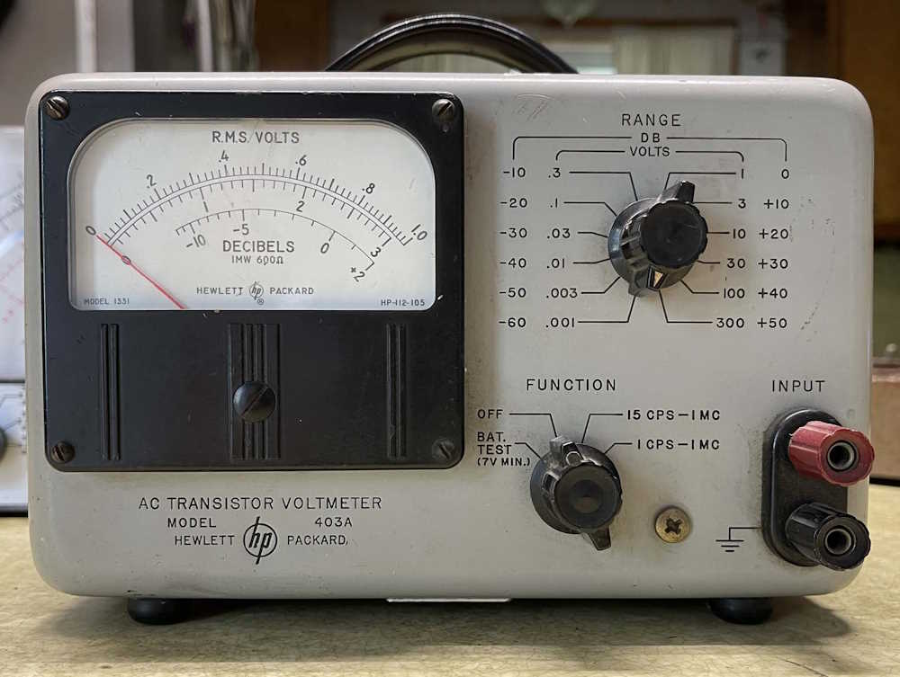
This HP AC Transistor Voltmeter Model 403A seems to be in good condition, and has a Westinghouse tag on the back. I can’t really test it because it has some odd battery requirements. It looks to need 5 mercury cell batteries - 2 4V batteries, and 3 1.35V batteries in a configuration that provides bias and + / - voltages. These are unobtainable, so a small supply may be in order if I actually want to use this thing.
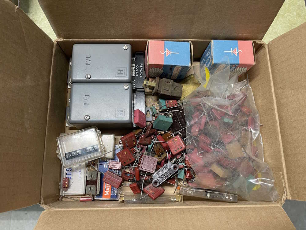
This came from a vendor that had boxes of parts. One part was $2, if you took the whole box it was $1. So…I took a box of mica capacitors and some other parts. High voltage mica caps can always come in handy.
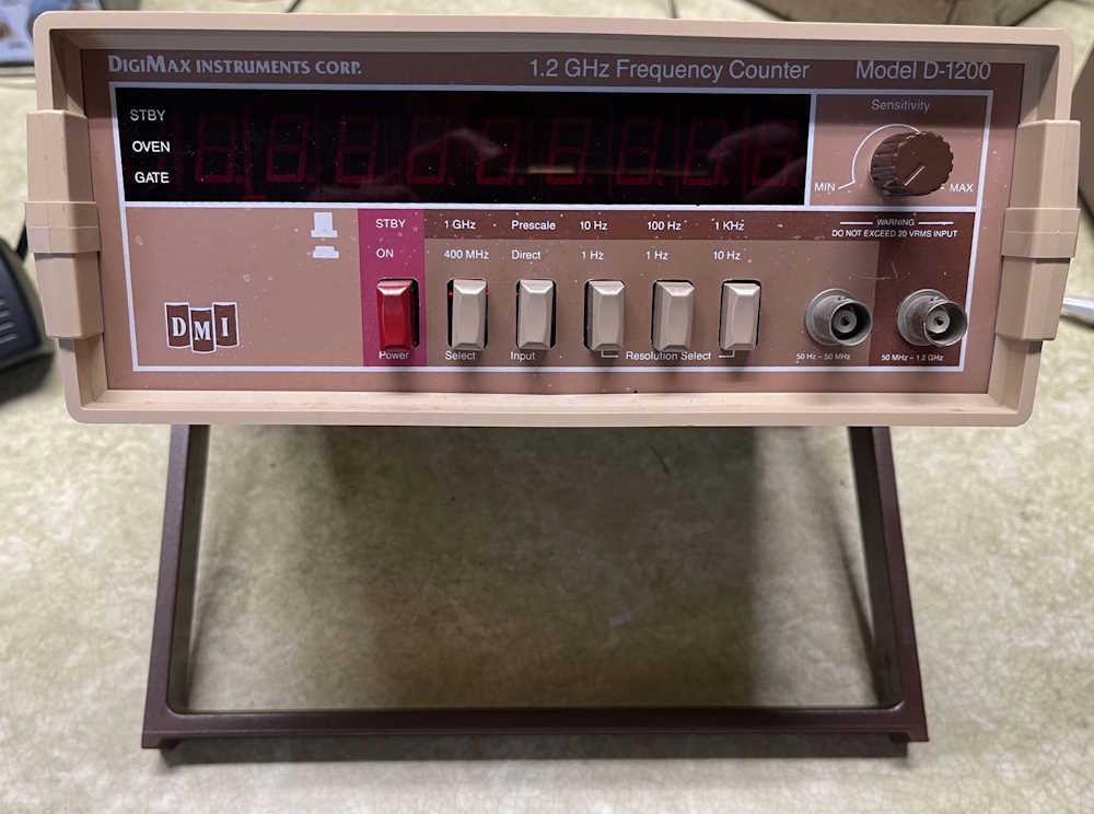
This DigiMax Instruments D-1200 counter claims to go to 1.2GHz, and has lamps for an ovenized reference on it. It’s awfully light, but it does light up. I need to get a signal in it to see if it’s actually counting, or if it’s just spitting out garbage.
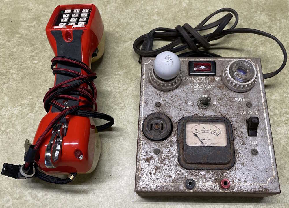
The Harris-Dracon butt sett was picked up becaue it was cool looking. I don’t know what I’ll use it for, but whatever. The Waage All-Purpose Tester Model 066 test box was a dollar - it’s mostly just an ammeter you can switch out, with a fuse and a lamp for testing the AC line. It’s pretty rusty, but looks clean inside. Who knows where this will end up.
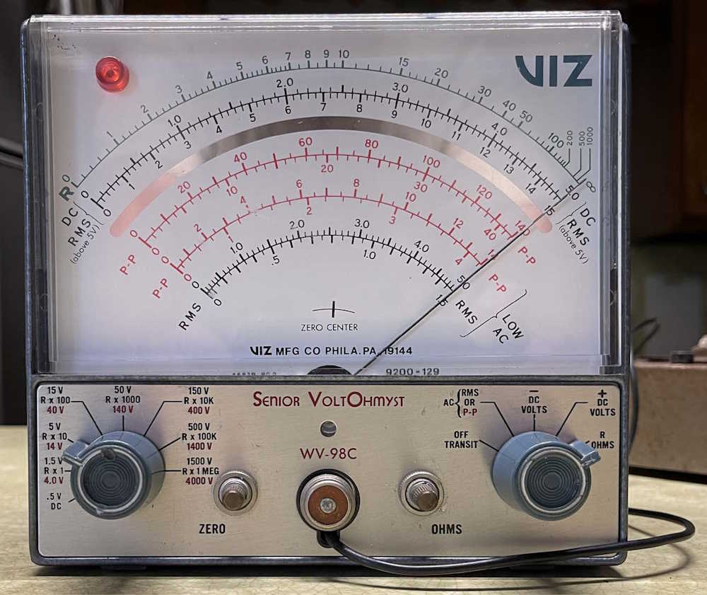
This VIZ Senior VoltOhmist WV-98C meter seems to be operational, and has a case you could kill a poodle with. It’s a two-tube unit, using a 6AL5 Dual Diode and a 12AU7 amplifier. It’s small enough to go on the bench instead of the giant EICO VTVM currently there.
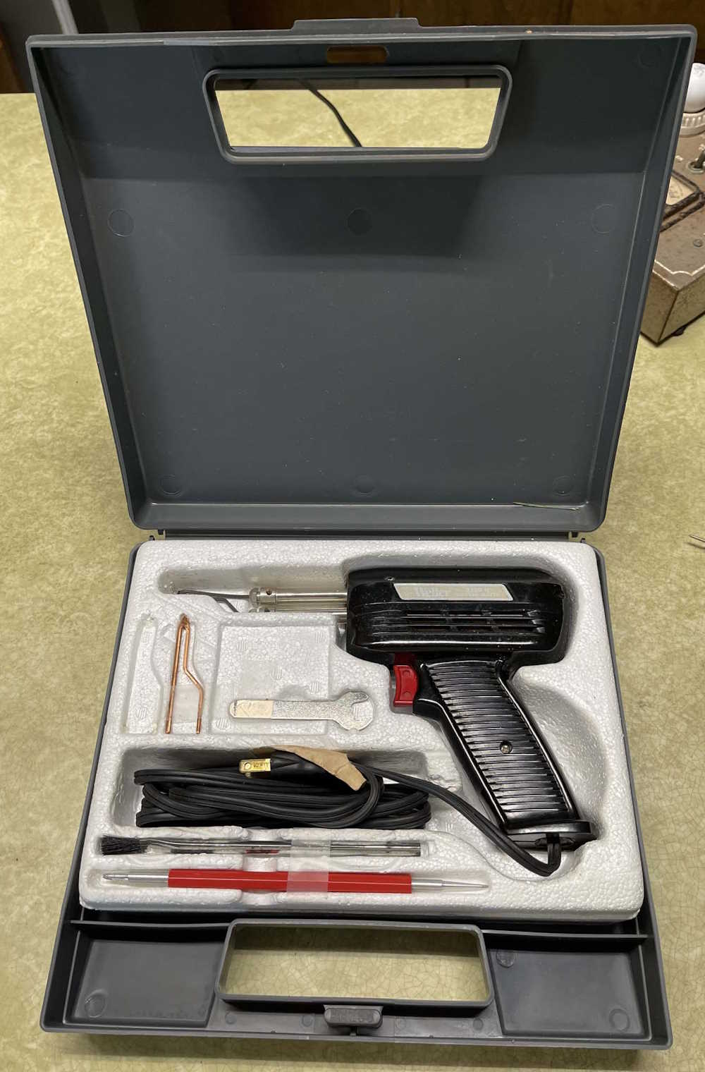
This Weller solder gun has all of the tools with it, and is one of the units made in the USA. I have a couple of these, they come in handy soldering chassis items.
That’s this year’s haul. I tried to limit myself to smaller items I could use, and I mostly succeeded. There were a lot of larger items that I wanted, but left there since I don’t have room for them. In all, I didn’t spend a lot and brought home some neat things.
Next show is either the Van Wert, OH show - that’s a long drive and may not be in the cards - and/or the Columbus, OH show which is a lot closer to me and much easier to attend. Either way, stay tuned for pictures from those shows, and I’ll see you there!
The VIZ and HP meters had some serious issues and became parts. The Waage 066 is now a lamp.
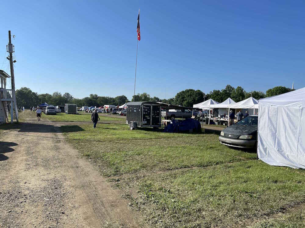
It was raining where I was, and threatened rain all the way to the show - but when we arrived, the sky had cleared and it was a sunny, slightly breezey 71F. Essentially, perfect conditions for wandering the aisles. While I didn’t see some of the things I hoped would show up this year, there was still quite a bit to look at. I spent a couple hours wandering the show before heading out for some lunch.
The usual mix of equipment showed up here, and a few things managed to wander home with me. This is what I saw at this year’s show:
I wonder if they will take my battery club card?
A BC-221AA Signal Generator.
A buck a box or two bucks per part. I took a box.
Motorola Communications Analyzers.
An old school engine analyzer.
Some equipment and schematic manuals.
This guy never prices stuff.
Don't bump the equipment stack.
The lighted switchbox up front was neat.
The VIZ meter in the middle went home with me.
An estate sale from a silent key.
Frequency doodads.
A floppy drive, and lots of solder.
A Boonton AM/FM Signal Generator.
A couple of neat chromed radios.
A Heath Weather Station with all the stuff.
An interesting Lafayette tuner on the right.
Something to monitor 3-phase stuff?
We go to shows for tables like this.
The 70s appear to be calling.
I swear one of these scopes exists for every person on the planet.
Yet another sig gen, this one branded Olson.
Some interesting rack mount radios.
More radios, who would have guessed?
Some Heath stuff.
I bet you can't guess what this is.
The scopes on the ground were free.
A big piece of Singer test equipment.
A bunch of GE radios.
A weird tape deck and some EQs.
A Tek 455 scope on it's cart.
A Tek 547 missing a plugin.
A bunch of odd testers. I took the one with the bulb.
Trans-Oceanics for parts.
A Knight radio and a tube tester, and stuff.
I don't know what this one is.
.
Next show will probably be the Columbus, OH hamfest, although there are some happening before that. Regardless, I’ll (maybe) see you there!
A recent LinkedIn post talked about a manager style the author calls the “Up your own butt” boss. You can read that post here: https://www.linkedin … edium=member_desktop. You may need to log in to see it.
A position I held several years ago had a direct manager that fit this bill. Everything good was “We,” everything bad was “you.” Blame would be shifted, even if he was at fault.
Shortly before I left, he stormed into a shared technician office and started berating us about someone charging time - in this case, weeks - to overhead. (Overhead at this company was a charge number that you could use when you were just doing general tasks that had no direct charge. Things like setting up new equipment, cleaning an area, etc.) He was going to find out who did this, they were going to be disciplined. Possibly even fired.
He knew very well it was him doing it. He was having a house built at the time, and would go spend hours on site harassing the builders.
He should have been fired for that, as this was weeks of time he did nothing and lied about it. There were other incidents that he should have been fired for, including destroying expensive equipment from negligence.
Unfortunately, it was endemic to the entire company. His manager - the chief engineer - had a severe god complex. He was incapable of looking at something and going “Good work men, you did a great job!” Instead, he would go “I’m a great man, look at what I did.”
I learned very quickly not to go to this man with ideas, he would discount them immediately, and then implement them under his own name.
It was a terribly toxic place and almost drove me to alcoholism. I’m not proud of that, but I got out with the help of a good friend. Bless you Lance, I’d be dead if it wasn’t for you.
This is a great local show, and has always offered a few hours of wandering aisles and some “Dayton items without the Dayton prices.” I really need to lay off buying more boatanchors this time, but I’m sure a couple will come home with me. The club had some things they were selling last year, one piece in particular should have gone home with be - if it’s still there, it will!
(The forecast is calling for possible showers. We’ll see.)
See you there!
Breezeshooter’s Hamfest
Butler, PA
Butler Farm Show (Kind of a fairgrounds thing)
625 Evans City Rd
Butler, PA 16001
June 9 2024
8A - 2PM
https://breezeshooters.org/ns/
While I’ve submitted the site indexes to both Bing and Google, you probably have a better chance of finding something here using Bing, or those sites that use it like DuckDuckGo. For all the grief Microsoft gives us, their indexing system is quite friendly. Submit pages via their console and it goes “Sure thing! Let me index that for you.” and a few days later - there it is.
Google, on the other hand, complains. “You have a redirect! I can’t index that!” Where? It’s a static page with a link on it. There are lots of things in the index queue that were rejected and I’m not even sure where it’s getting them - it looks like it’s own temporary files are being indexed and then tossed out because they’re not there anymore. it complains about invalid pages but give no reason as to why, just that they aren’t.
Regardless, for all the crap - Bing works best if you’d like to find an old post from a search engine. Use https://www.bing.com … =site%3awereboar.com and you’ll get a pretty good list of things here on wereboar. Bing feeds other sites like DuckDuckGo and Yahoo!, so you can use those sites if Bing isn’t to your liking.
If you’d like to stay on wereboar, you can use the built-in popular post page to see an index of all the pages, and how many times they’ve been viewed. Check that out right here: https://wereboar.com … projects/popular.php
And finally, the third way you can “search” the site is to use the sitemap. This one is just a text file with all of the important URLs on wereboar. There are no titles, so this is probably not an ideal thing to use - it’s primarily so search engines can find the URLs. However, if you’d like to see it, it’s here: https://wereboar.com/about/sitemap.txt - and the auto-gen’d XML version lives here: https://wereboar.com/about/sitemap.xml.
While I can’t take suggestions here due to the large amount of spammers, please feel free to connect with and talk to me on LinkedIn: https://www.linkedin … an-walker-525b41223/ - I’d love to know what you think, and would like to know if there’s something you’d like to see more (or less!) of here on wereboar.
Thanks for checking out my place. See you soon with more goodies from shows and junk I’m working with.
2026 update: I’m going through and cleaning up the site, making images better for size and naming, and adding keywords and titles for search engines. Hopefully you should have an easier time finding something here.
Sunday was a slim day - many of the vendors pack up Saturday evening, but maybe 1/5 were still on the grounds, not counting the exhibit buildings. Lots of reduced price deals and some free stuff were around today, and I still managed to bring home too much. Today’s lunch was Bourbon Chicken and a milkshake - a bottle of sauce managed to make it home as well. In all, this was a good show even if Friday was a bit messy. It’s also the first year I didn’t go through the exhibit halls, but there’ s nothing in there I needed this year.