- 2025
- Jan
- 14
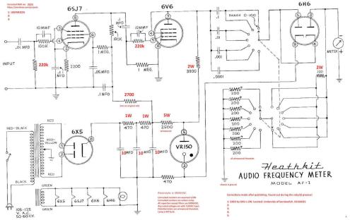
The Heatkit AF-1 Analog Frequency Meter, Part 3 - Schematic Corrections.
I didn’t have (and couldn’t find) a manual online for this device, but ManualMan had a reproduction manual available. This was my first time ordering one of these, and I can highly recommend this service. The manual is a comb-bound booklet with cardstock covers and a large, fold out schematic. If you want something that resembles the original, this is your stop.
You can check them out at https://www.manualman.com/.
I procured that because my unit and the schematic I found online differ, and some things I’ve seen elsewhere suggest that the online version is a pre-production schematic taken from the Heathkit schematics book. The schematic in the manual has resistor wattages, capacitor voltages, and a component that doesn’t exist on the pre-prod version. I’m not going to copy the manual that I purchased (but will copy a version that I find in the wild, if one exists) here, but I’ve made corrections to the schematic that’s online.
My corrections are in red, but the compression on the image may make it difficult to read. Click this for a larger version suitable for 11×17 printing.
Future me note: This is not the final schematic. You can find that in the wrapup post, or at this link.
Next is to make some decisions about parts. I’ll probably keep capacitors at their specified voltage (or higher) even though nothing more than 400V should be present. Resistors will keep their wattages, or in the case where multiple wattages of the same resistance exist, I’ll just use the higher wattage for everything so as to buy components in bulk.
Stay tuned for the parts list in part 4.
Next part of this series: https://wereboar.com … -meter-part-4-parts/
Previous part of this series: https://wereboar.com … eter-part-2-testing/

