A PACO G-30 RF Signal Generator - Part 4: The power supply.
Wednesday, April 23, 2025 at 11:54:27
First things first, this device needs it’s input and power supply corrected. This involves adding a new polarized power cord, replacing the across-the-line capacitor, and replacing the selenium rectifier and capacitors with a silicon diode and new capacitors.
The across-the-line capacitor is two capacitors back to back, with a common leg.
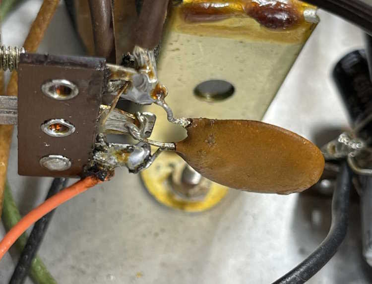
It’s really amazing that this thing isn’t cracked in half. Two new safety capacitors will go in it’s place.
The unit had new capacitors installed by the former owner, but I didn’t like they way they looked.
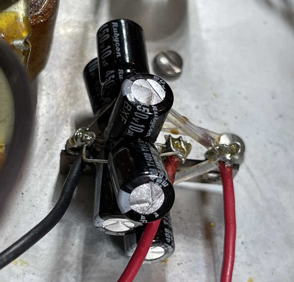
I understand the person probably used what they had on hand, but still. This is kind of sloppy, but it worked. Note that the capacitors are 450WVDC…
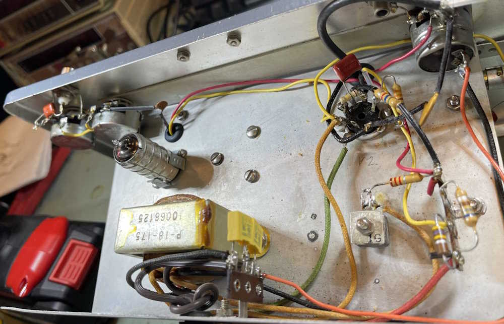
The first thing to do here is start removing parts. I’m going to use the screw for the tuning capacitor to hold a new terminal strip, and put a new hole in for a second, so I can string the new capacitors out a bit. This also gives me room to add a new dropping resistor, since I have to account for the voltage drop of the selenium diode. The old safety capacitor was removed, as was the old line cord.
All of the new parts were added in save for the dropping resistor in-between the two capacitors. I intentionally left that out just in case I needed to experiment. I’ve seen others doing this same task, and they’ve come up with a 3.3kΩ resistor, so I decided to start with that.
Regarding the dropping resistor: You’ll note that the original was a carbon comp part rated for 1/2W. While I’m going to more modern oxide and film resistors, I stepped the power rating up. Why?
CC resistors had the ability to withstand a good current surge, especially if it was quick. Modern film resistors do not have this ability, and can act like a fuse - especially in circuits like this where capacitors are going to be charged immediately when the set is turned on. You get that small surge of current, and that can destroy things. Since modern parts are smaller for the rated values, I chose a relatively inexpensive 5W oxide part for this section.
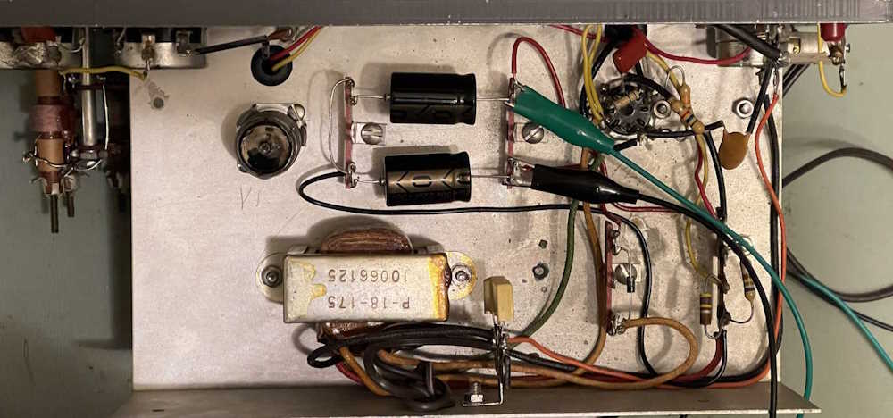
After removing all parts and installing their replacements, I set up for some testing:
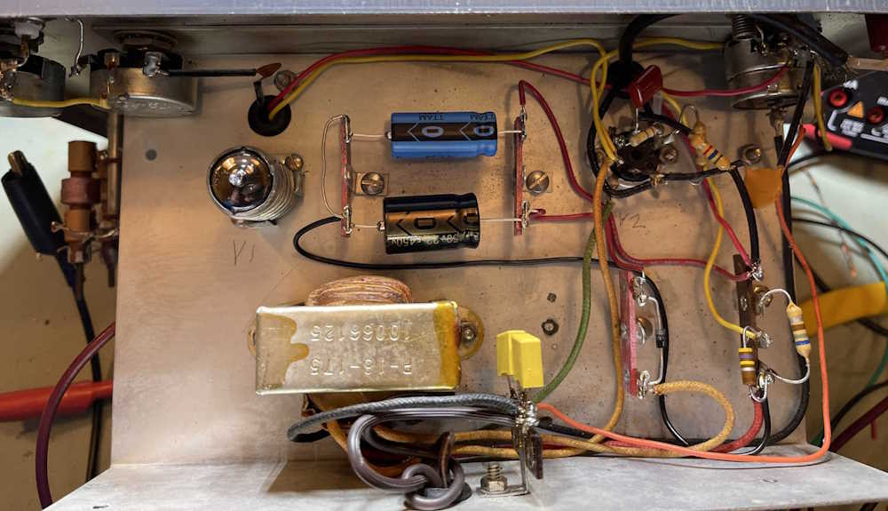
I used a 47μF in place of one of the capacitors, mostly because the previous owner put 30μF in for both sides of the filter. It’s not that much of a stretch to go from 20μF to 50μF, especially with a modern diode in there, and the effect of the dropping resistor limiting current at startup.
After a quick wiring check (make sure those wires from the transformer are correct, the red color on the red/yellow line has long since faded to nothing!) I clipped the resistor in, and applied power.
B+ was 180VDC.
On a 150WVDC capacitor. Whoops. Turn it off. What went wrong here? Well, it was staring me in the face, but I did a test with the original selenium rectifier. Same thing, only about 170VDC. The selenium obviously had a voltage drop, but it wasn’t enough. What was going on here - the original parts were only rated for 150WVDC.
I think I know what’s going on here, and it’s related to the rectifier type of the circuit. A solid-state device performs differently than a tube device, and the OEM took advantage of old part characteristics when designing the unit. I changed the 47μF with another 22μF @ 450WVDC part, applied power, and…
Upon powering the unit, the B+ went to 180VDC - and then dropped as the tubes warmed up and started conducting. Just as expected, once the circuit was operating the B+ fell right in line at 109.1VDC (s/b 110) with an input of 120VAC.

So why did this happen? In a pure tube circuit, where the rectifier is also vacuum, you have a circuit that warms up together. That is, the full B+ probably won’t be available until the rectifier is hot - by that time, everything else is hot and wanting current, so you have a proper load.
A selenium circuit, however, has B+ available the minute you turn the set on, as the selenium stack is essentially a primitive semiconductor diode. You’ll have full line (120 * 1.414 - Vf) peak there - until the rest of the circuit is hot and wanting current. Only then do you have the proper loads and can expect B+ to be the nominal value.
But the original part was only 150WVDC! Yes, and that’s because those old paper capacitors could handle surge voltages for a short time, and they didn’t care. Sure, it may have shortened the life some, but 20 years later it’s dry as a bone anyway, who cares. You need to rate your parts for the full peak voltage you’ll see on the device! A 250WVDC part would have been fine here, but I have 450WVDC parts - so in they go.
I can always add more capacitance if there’s an issue, but it’s back to where the OEM had it.
So, that’s on me. I forgot things I learned 35 years ago and never used until today. But now I know, and if I (or you!) run into a selenium powered circuit that you want to retrofit, you have a better idea of what to expect.
Next is resistors. While some have been changed, and everything else is right on tolerance, I’m going to replace them anyway because they’re almost all carbon comp resistors. I was only planning on changing a few, but there’s no need to leave the old ones in there - resistors are cheap, and making this thing ready for it’s next 50 years is what I’m trying to do here. I have a few on order, as soon as they get here I’ll solder the dropping resistor into place and get started on replacing other parts.
Stay tuned!
Next part of this series: https://wereboar.com … or-part-5-resistors/
Previous part of this series: https://wereboar.com … erator-part-3-parts/
Wrapup and link to all posts: https://wereboar.com … rator-part-7-wrapup/