A PACO G-30 RF Signal Generator - Part 5: Resistors
Monday, April 28, 2025 at 07:20:09
After confirming the power supply was operational (and remembering how that works!) I started in on the resistors.
Some had been replaced before I received the unit (foreshadowing!) and some were original. It was a mix of modern film, old film and old carbon comp resistors. I have to wonder if these were the special military units, as the remaining carbon comp parts were well within tolerance. Considering I’ve seen multiple of this particular device and every one of them has a different style of parts inside, it’s hard to tell.
I decided to just do them one at a time. Unsolder, remove, and replace with the same value. At least, the same value as what’s in the unit now.
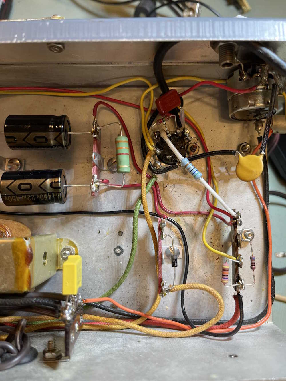
Here’s the bottom after replacing the resistors, diode, and capacitors (yay bad lighting!)
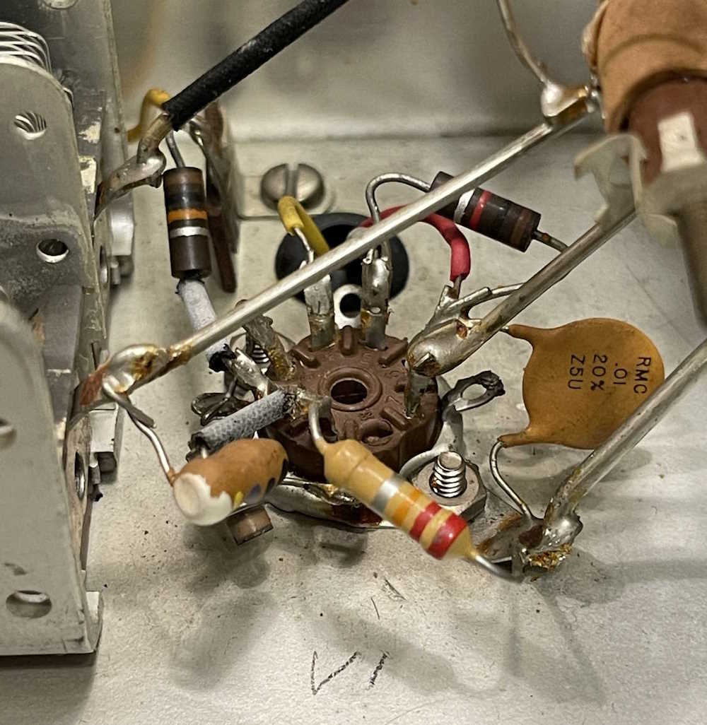
This is what the top looked like before replacement:
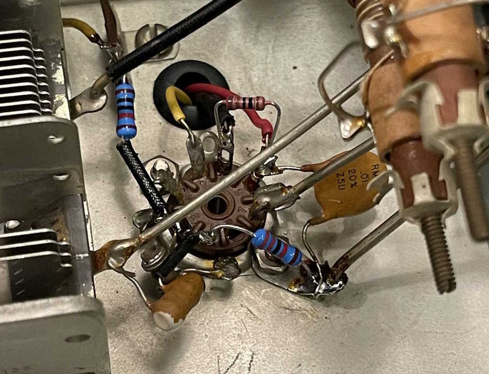
And after:
After a quick inspection, I fire it up. RF looks good - for the given value of good this device offers. The audio side? Not so much, there’s nothing there. Uh oh…stay tuned for troubleshooting.
Next part of this series: https://wereboar.com … t-6-troubleshooting/
Previous part of this series: https://wereboar.com … -4-the-power-supply/
Wrapup and link to all posts: https://wereboar.com … rator-part-7-wrapup/