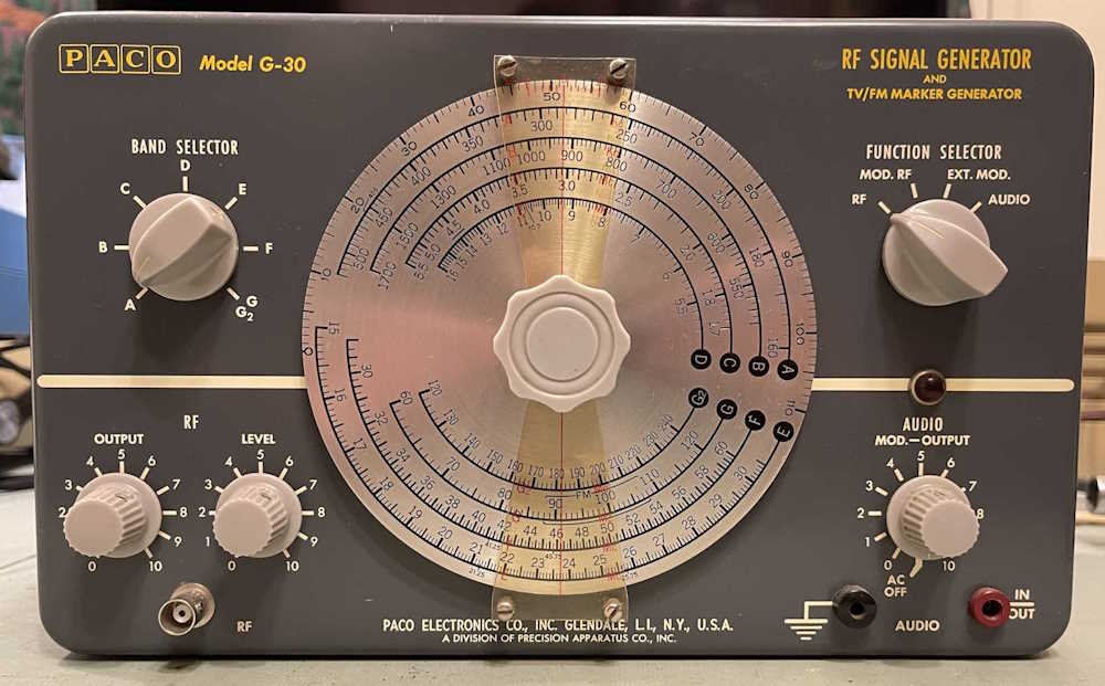
A PACO G-30 RF Signal Generator - Part 7: Wrapup
Wednesday, April 30, 2025 at 11:48:08
Now that the PACO G-30 is working, and is probably in a bit better shape than it was than before I purchased it, it’s time to take a look back on what happened with it.
Analysis and wrap-up.
When I purchased the unit at Findlay 2022, it was sold working. And it was - mostly. I didn’t check the audio portion, but the RF worked fine. The previous owner had removed some of the old capacitors and replaced a few of the carbon composite resistors. He hadn’t replaced them all as they were well within tolerance - surprising for high-value CC resistors. He had replaced the filters with a strange array of electrolytics. But what hadn’t been replaced was the across-the-line capacitors, as well as the selenium rectifier.
The across-the-line cap was of the three-leg type, a device that has two units back to back with a common leg. They’re well known for blowing apart, and that this one hadn’t done so was surprising. The other device was the original selenium rectifier.
Selenium devices were a stop-gap measure between vacuum rectifiers and silicon rectifiers. They worked fine when new, but as they age the forward voltage drop of the device increases. This happens used or unused. Get enough resistance there, you get more voltage drop, more drop means more heat, more heat means that eventually you’re going to wind up with a device that burns open and releases a lot of toxic smoke into your space. You don’t want that, so replacing it is mandatory. Sure, it’s probably still going to work (for a while,) but it’s a case of when, not if it goes bad.
For the most part, this was just a replace the parts that are known to go bad (mostly done,) replace the carbon resistors because they will eventually go bad (mostly done,) and fix some of the issues left by the previous owner. The across-the-line capacitor was easy enough to replace with modern safety caps, and the old line cord was replaced with a new polarized cord.
As stated, the selenium rectifier is a part that was destined to fail from birth. It needs to be replaced, and for a small rectifier like the one in this device, it’s easy to replace with a 1N4007 silicon. I used this type because I have them on hand, but you could use any diode that exceeds the miniscule current rating, and at least 200V. (You should go higher than this for safety margins.)
There are some considerations to look at here. You’ll need to remember that the silicon rectifier drops much less voltage than a selenium, so some sort of dropping resistor will be needed. There was already a 2.2kΩ resistor in the power supply circuit between the two filter capacitors, so changing that was easy. You’ll need to make sure to measure the current to do some basic calculations and see what you need to raise that value to, but in this case I already knew ~3.3kΩ would work as others have taken the time to do the calcs.
Another consideration you’ll need to make is that full peak voltage of the line will appear on the capacitors until the set is warm and drawing current. Therefore, any capacitors you use will need to handle at least this voltage. The old ones may not have been rated for this, but those old paper capacitors could handle surges much better than modern stuff. Modern parts are easier to get with higher voltages, so don’t be afraid to use 300WVDC or 450WVDC capacitors here.
Resistors are the last consideration you need to look at. Remember that you’re working with higher voltages than a battery device - you need resistors rated for at least your maximum B+ voltage, be it the rectified voltage or the Peak voltage that you see on the filters. Most resistors are rated for at least 300WVDC these days, so you’re good for this device - but if you’re working with 400, 800, or higher - your resistors need to be rated for this higher voltage. In carbon resistors, you’ll see ones that are longer than normal and that gives you a clear indication that it’s a high voltage part. Modern parts give you no such indication, so buy your parts from a reputable house.
Resistors also have to be rated for your surge currents. Carbon resistors can handle surges, and that’s especially important here where you have full voltage on your circuit at the start. Rate it small, and your metal film resistor is a fuse. Don’t be afraid to step up the power rating on resistors in power supplies and other areas where you’re going to be supplying current and voltage to the rest of the system.
What did I specifically run into?
First - I forgot how selenium rectifiers work in a vacuum circuit. It’s been far too long since I’ve seen this type of device, so it took some remembering.
When I first turned on the set, I had a 150WVDC capacitor after the dropping resistor. As the entire of the peak line voltage appeared here (180VDC) I went crap and turned it off. It took a while to remember that the rest of the set isn’t hot and wanting current, so the voltage drops in the power supply aren’t there yet. A quick swap with a 450WVDC part and a bit of waiting, and B+ dropped right back to where it should be, which is ~110VDC.
Second - I didn’t have any audio on the audio side. This turned out to be a part the previous owner installed. The grid of the audio oscillator was supposed to have a 100kΩ resistor, The previous owner had a 15kΩ resistor here, which is what I replaced it with as I replaced each component individually with it’s modern equivalent. Once I put the proper value in the circuit and a new tube (the old one didn’t seem to work well) it came right up. It’s a bit off in frequency, but it’s not really of importance as it’s there for you to hear, not compare to the sounds of nature.
This unit is a good example of why you examine devices closely when you’re working with them - especially when someone else has been in there first. A schematic is essential for this, so make sure you have all your docs in order.
That’s about all - other than the wrong part leftover from the former owner, this was a simple “bring it into the modern age” device. Next up is probably an Eico 24x VTVM, but it’s also another “just needs resistors” device. It just needs a lot of resistors as the divider ladders in the measurement circuit are all out of tolerance. Stay tuned!
All of the posts in this series.
A PACO G-30 RF Signal Generator: https://wereboar.com … rf-signal-generator/
A PACO G-30 RF Signal Generator - Part 2: Revisiting https://wereboar.com … r-part-2-revisiting/
A PACO G-30 RF Signal Generator - Part 3: Parts https://wereboar.com … erator-part-3-parts/
A PACO G-30 RF Signal Generator - Part 4: The power supply: https://wereboar.com … -4-the-power-supply/
A PACO G-30 RF Signal Generator - Part 5: Resistors: https://wereboar.com … or-part-5-resistors/
A PACO G-30 RF Signal Generator - Part 6: Troubleshooting: https://wereboar.com … t-6-troubleshooting/
A PACO G-30 RF Signal Generator - Part 7: Wrapup: You’re reading it now!
Previous part of this series: https://wereboar.com … t-6-troubleshooting/
Addendum - It was pointed out to me that some of the other parts installed by the previous owner are incorrect, per the schematic.
A PACO G-30 RF Signal Generator - Part 8: So we meet again: https://wereboar.com … -8-so-we-meet-again/