The Heathkit AG-7 Audio Generator part 2: Testing
Tuesday, June 10, 2025 at 11:15:35
In the last post, we determined that this device was mostly operational, but had one of the problems you see with wien bridge oscillators - one side of the output signal was clipped. That can be an issue with not enough or too much drive in the feedback circuit, so I decided to do some tests.
Here’s the schematic for this device:
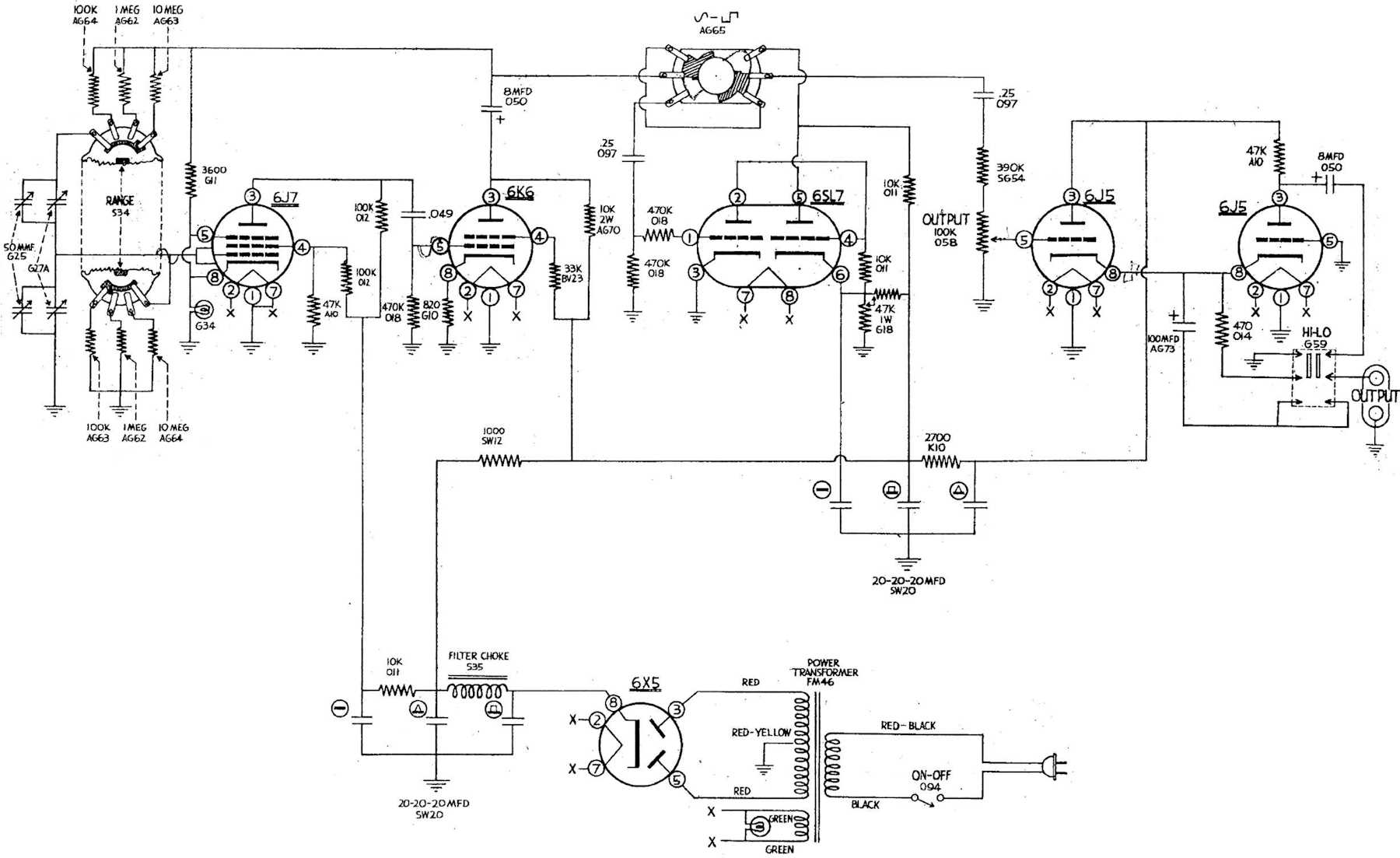
An oscillator is an amplifier that provides it’s own input. You’ve probably run across that with feedback on a public address system - that’s the amplifier becoming an oscillator.
In this case, it’s controlled oscillations that we’re looking for. To do this, this particular oscillator model provides two kinds of feedback. Positive feedback, which is the actual oscillator drive and is controlled by the frequency selection capacitors and resistors. And, negative (servo mechanism) feedback that is provided by a lamp used as a positive temperature coefficient resistor - that is, the more current the circuit tries to draw, the more the lamp resists that and tries to keep the gain stable.
The reason you need the servo mechanism is because the oscillator will continue to draw more current until it reaches the limit it can draw from the supply - and probably clip and/or destroy things. The lamp is a quick and easy way to stop that, and was used in almost all oscillators of this type. Later ones used an FET or other current control method, and modern DDS generation doesn’t need this.
Before I tried anything, I swapped the bulb with a new one. No change there.
I’m going to start with checking the oscillator and feedback loop to see if the distortion is present in the oscillator. Pin 3 of the 6k6 Pentode is the output amplifier for this part of the circuit, so checking on Pin 3 should reveal most of what we need to know:
And the distortion is there, so we can probably assume that it’s present in the whole circuit.

(The schematic doesn’t show the suppressor grid - Grid 3 - on the 6K6, but it’s there. It’s tied to the cathode internally, so some manufacturers didn’t show it since you couldn’t access it.)
So that means the input to the 6J7’s control grid is probably distorted as well.
It is.

So it follows that the input to the 6K6 is also bad.
It is, and it’s quite high - perhaps this needs to be cut down some? (It’s inverted because each stage acts like an inverting amp, so the distortion is at the top now.)

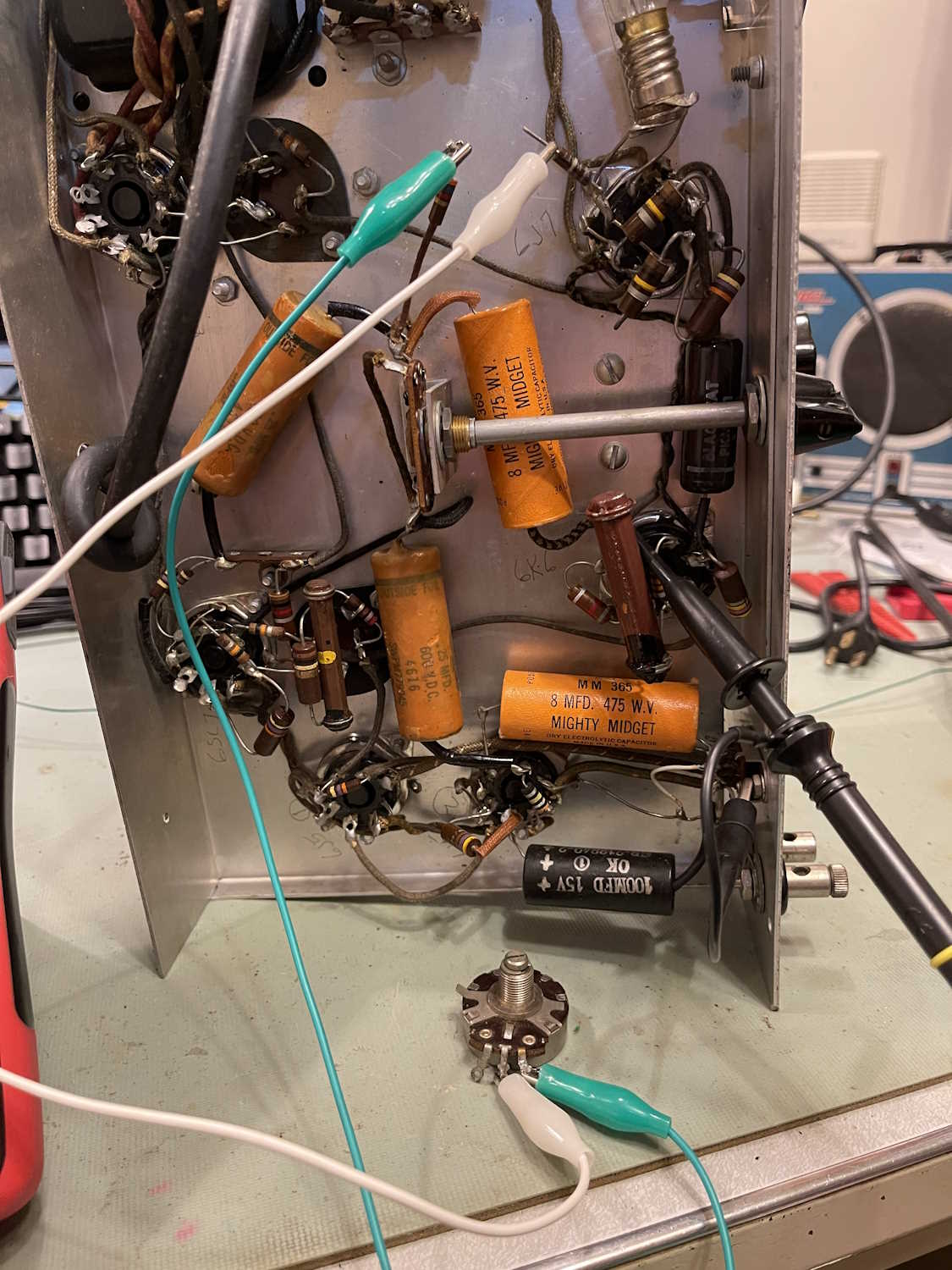
Before moving on to the interconnect between the two stages, I decided to examine the feedback loop. Breaking the two resistors, I put a potentiometer removed from the Heathkit AF-1 in-between the stages.
Interesting - more resistance caused the device to go into severe clipping:

Less resistance did nothing much. One thing I did notice is that too much resistance will cause the oscillator to become unstable - this explains the problems I’m seeing with the BW200 oscillator that was on the bench recently.
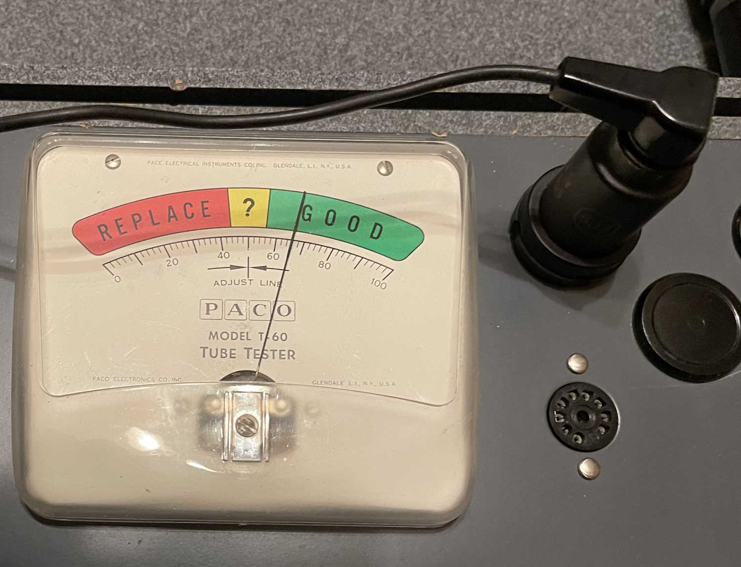
I was going to move on to the interconnect between the stages (plate of the 6J7 to the control grid of the 6K6) but something happened. I had no output at all, and I’m not sure what happened. Did something pop, like one of the capacitors? The tubes seem to check good:
I need to do some more checking on this thing before making my decisions about what’s going to happen to it.
Next part of this series: https://wereboar.com … or-part-3-diagnosis/
Previous part of this series: https://wereboar.com … part-1-observations/
Wrapup and link to all posts: https://wereboar.com … rt-9-final-thoughts/