- 2025
- Sep
- 18
Modifying the Ikea Inspelning smart plug for always-on operation.
Disclaimer: This involves working with high voltages and high currents, and is a device that you’re going to plug in to a wall outlet and leave there. Make sure you’re comfortable working with this kind of stuff before proceeding! This is a guide and you need to know what you’re doing beforehand. If you don’t - don’t! Mistakes can destroy property and kill you.
Ikea is one of the oddest stores I’ve run across. Known for their flat-pack furniture, they also have a line of relatively friendly and cheap technology devices that operate on common standards. One of these devices is a smart plug called the Inspelning (translation: recording.) It’s available in multiple countries with different outlet formats, but the one I’m going to be concentrating on is the North America version.
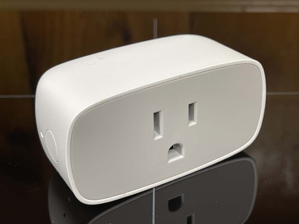
This is a generic ZigBee compatible device that offers both remote control via their own hub and other compatible devices, as well as providing both power consumption and line voltage monitoring functions. It exposes these via Ikea’s own application, or by entities within Home Assistant or some other smarthome system. I’m using Home Assistant, and these have no issue integrating and exposing all information.
So what’s the modification?
These are cheap devices at ~$13 - and you’re not going to find something with a power monitor that’s much cheaper. But…they can also turn on and off, which means if you’ve connected something that relies on being powered on all the time, having an accidental trip that shuts it off could be problematic. My modification is to make the device permanently on. This also has the effect of preventing premature power supply failure, which can cause relay issues and seems to be a common failure mode with smartplugs in general as the components inside are as cheap as you can get. I want a power monitor, not a remote plug, and this is a way to do it.
First thing is to get the device open. These are relatively benign, and are just clipped together. There are 6 plastic clips - two on the top and bottom, and one on each side. I don’t have any pictures of opening because it’s not a picture friendly process, but here’s how I did it:
You’ll need some sort of opener tool. I used iFixit’s blue spudger tool to pry a bit of the top of the case back at one of the clips and then pry up the gray plastic face. I then used one of their “guitar picks” to hold it open while I used a butter knife to pry-pop the rest of the face off. If you’re careful, the gray plastic should deform enough to release the clips on the sides.
I tried using the spudger to go all the way around, but the sides are simply too curved to get a good entry point, and not flexible enough to pry. I wouldn’t try this with a device that’s been around for a while, but a new device should have enough flex left in the plastic that you’re not going to break anything. Try not to insert anything in the lower part near the ground hole, as there’s a piece of circuit card that sticks up in this area.
Once the face is off, it’s relatively simple to access the circuitry.
First, remove the ground lug assembly. This just falls out, as it’s set in a hole. Set it aside. This isn’t connected to any of the circuitry inside, so if you needed a two-prong device to replace something like an old X10 two-pin appliance module, this is the way you could do it. I don’t suggest you do this, however, as modern outlets are all grounded.
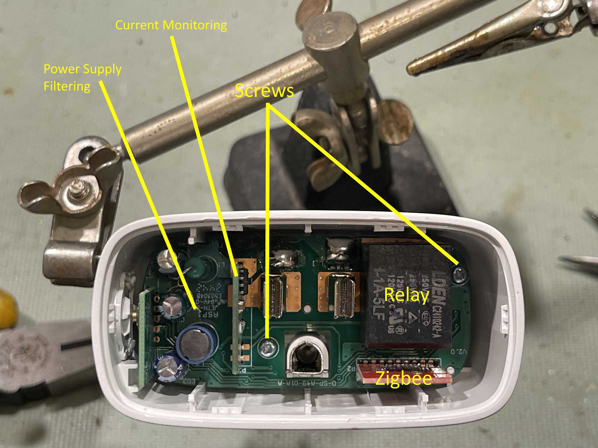
I’ve named the various parts, but we’re not really interested in anything but the screws. These are extremely shallow philips screws, so you’ll need something to fit them. I didn’t have the right kind of driver handy, so I just used a thin blade flat to catch and back them out. Don’t apply a lot of force to these, they’re really cheap and wanted to destroy themselves.
The other parts here are the relay itself, the zigbee control board, the current monitor board, and the power supply filter capacitors. Chances are the latter would need replaced if you encounter a situation where the relay chatters or becomes unreliable, but that’s not a given and outside the scope of what is being presented here.
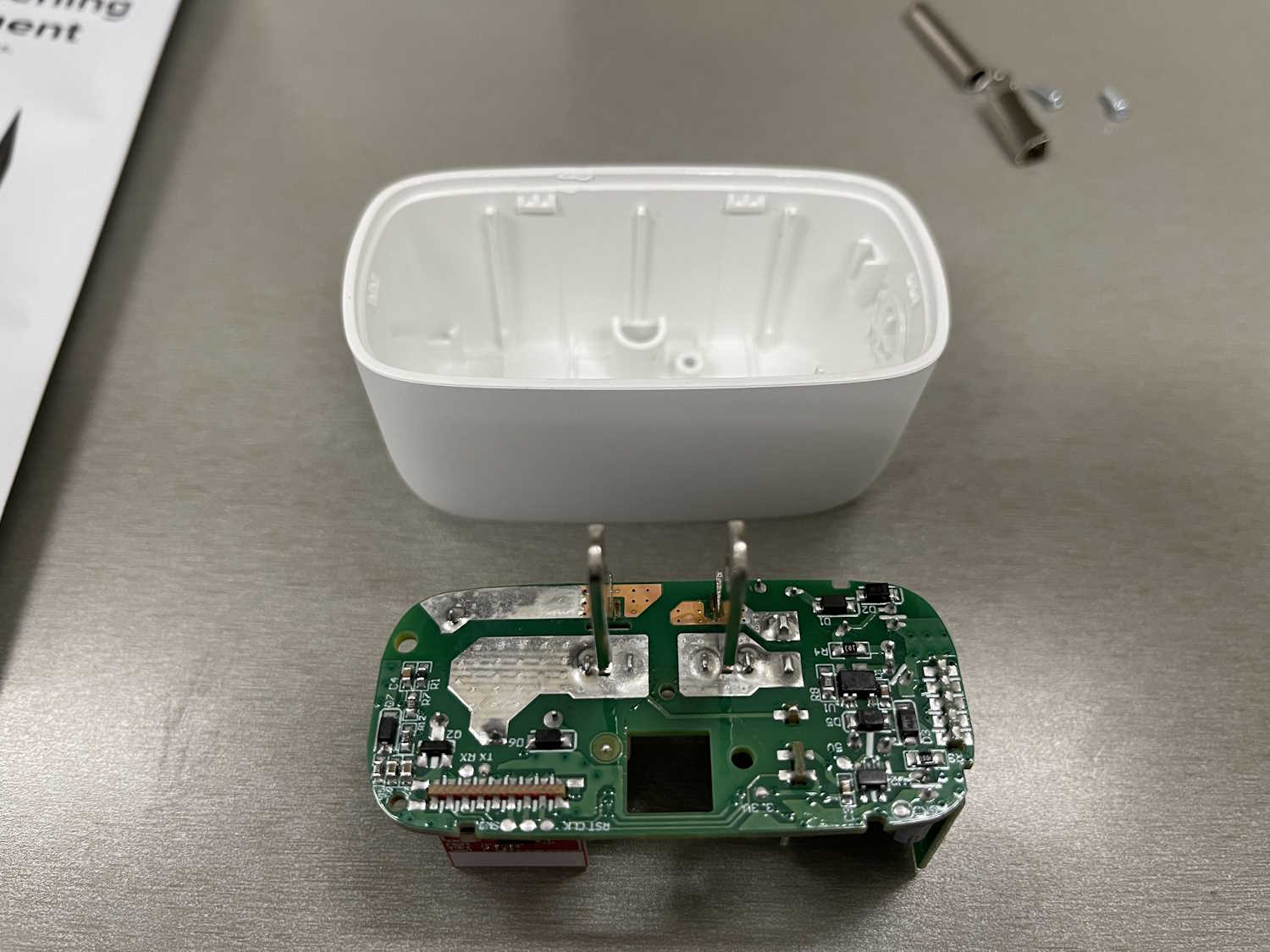
Push up on the plug tines to move the board to the top of the case. There are little pips that help keep in inside, you may need to gently wiggle to get it out. Avoid pulling on the control boards.
The back of the board reveals what we’re after.
There are two large soldered pads on the left of the board. This is the area that the relay connects when it closes, and connects the hot tine to the hot receptacle on the front of the board. The current monitor is in the neutral line, and is always active so it doesn’t matter if the plug is “on” or “off.”
We’re going to jumper across the hot line pads to create an always on loop. You can still activate the relay at this point, but it will do nothing.
CAUTION - you’re working with something that’s going to be plugged into the wall and will be conducting a potentially large amount of current. Make sure your connections at this point are well-soldered and using a properly rated gauge of wire. A half-ass connection won’t do it here.
I’m going to use a piece of 12ga solid from a strand of THHN. I’ve cut a section and bent it around a pair of needlenose pliers, then trimmed it.
Why a U-shaped piece? Mostly to give plenty of area to solder. You don’t want this thing coming undone inside the case, and the solder is going to be part of the 120VAC conduction area. Err on the side of caution here, give yourself plenty of area that’s soldered to and touching the pads.
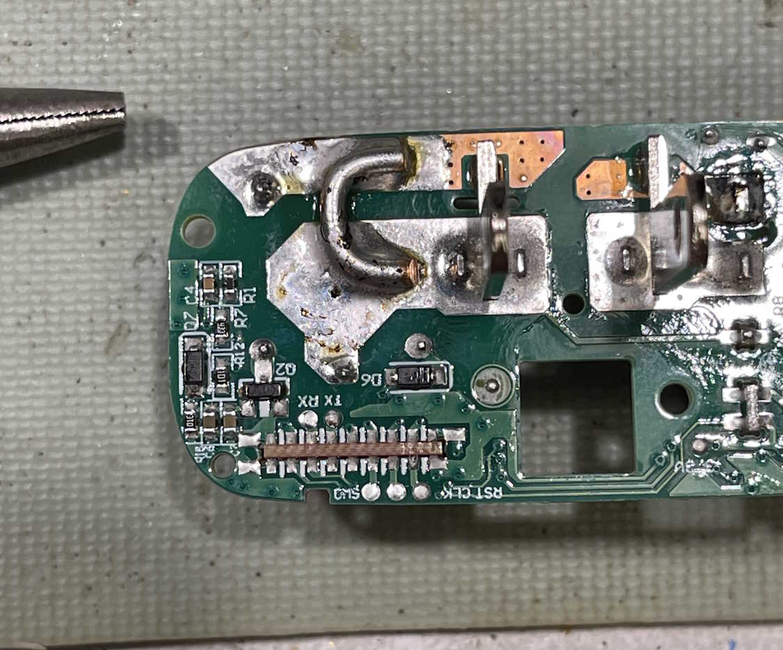
Make sure you have a good fillet all the way around the jumper.
Note - you’re going to need a decently hefty iron to do this - your little 20W SMT iron won’t cut it. A good 35W with a flat tip should work, but I used my 80W iron. Make sure your wire is pre-tinned and put a little solder down first. It will probably take a bit of doing to get a good placement, but make sure your wire has a good fillet all the way around, and is centered well in your pads. Don’t let any solder or wire drift off near components.
This should be good for at least what the relay offered, probably more since that relay is about as cheap as you can get.
Assembly is, of course, the reverse of disassembly. Install the board, the ground lug (make sure the flat is lined up properly with the area meant for it,) the screws, and snap the face back on. Do a quick ohms check between all 120VAC connections to verify there’s no shorts, and if good - plug it in and connect it to your smart devices monitor system.
I added mine to my test devices area and got this:
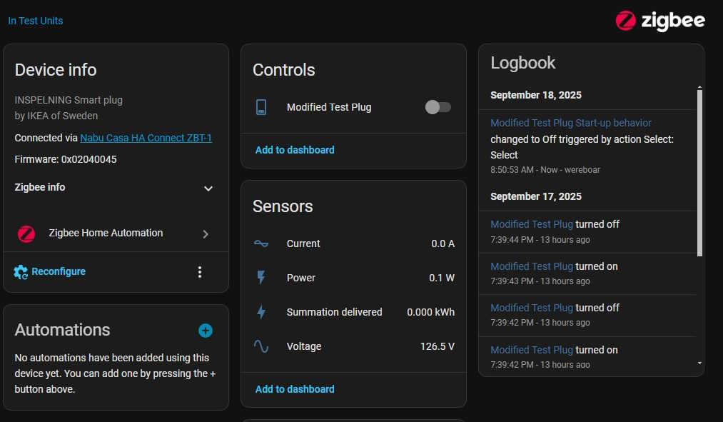
It’s reporting no current draw (other than the dithering these show) and is correctly reporting line voltage. The plug is not “on” as this point, although you can clearly see it still understands the button press. I suppose you could use this as some sort of scene selection if you wanted.
That accomplishes what I set out to do. While there are a few companies that provide non-controllable devices that do the same thing, this is by far the cheapest way of doing it.
One final note, Ikea has announced that they will be discontinuing the ZigBee devices at some point in the near future, in favor of Matter. I assume that just involves replacing the control card, but who knows. Get them while you can!