The Heathkit AG-7 Audio Generator part 9: Final Thoughts
Wednesday, October 15, 2025 at 09:01:11
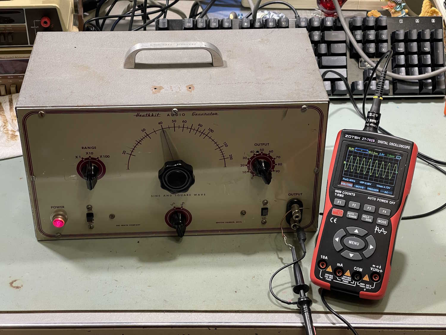
The Heathkit AG-7 is rebuilt, and is working - as far as I can tell, as designed. Internal oscillator measurements show that the wien bridge is working as expected.
This was the main issue from before - the amplifier was being overdriven as it was fed back into the circuit, and the bottom was being cut off. This was due to almost every resistor in the circuit being out of tolerance. New parts corrected all of the issues.
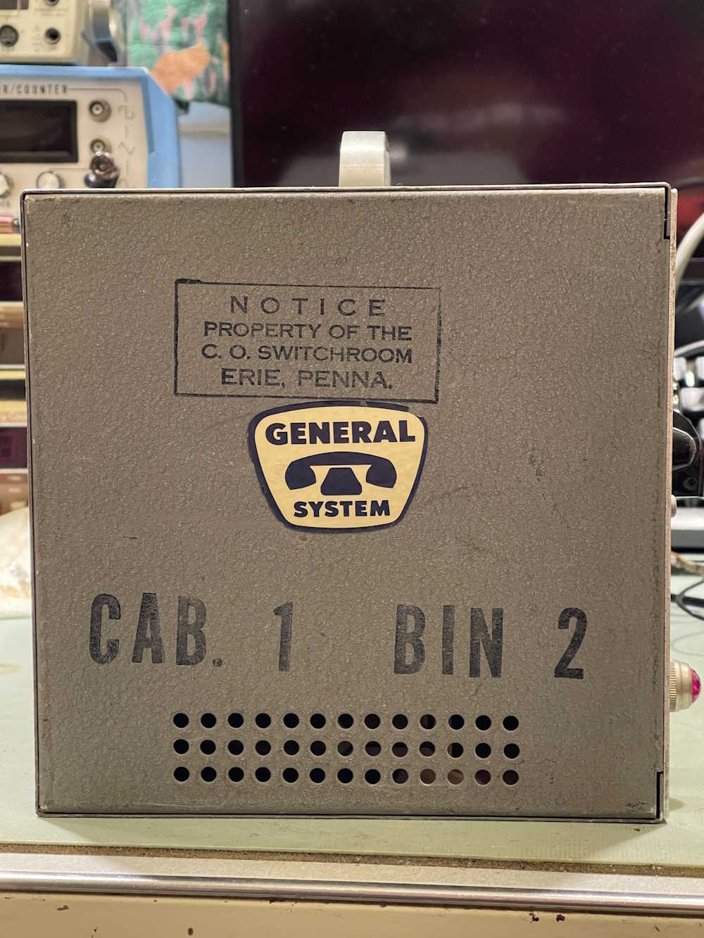
This unit was purchased at Breezeshooters Hamfest in Butler during the 2023 show. (Unfortunately, I didn’t get a picture of the device on it’s table…I think that was because we were walking out, I saw it, and took it home.) I didn’t need it, but it has some interesting markings - primarily that of GTE (General Telephone) indicating that it was owned by said telephone system, and that it sat in a rack somewhere. There were also holes on the front panel that would be about the size of a strap that would hold knobs in place. I assume this unit was probably sitting in a rack generating a tone for craft access during it’s lifespan. There were several repairs inside, indicating to me that the unit had a long life.
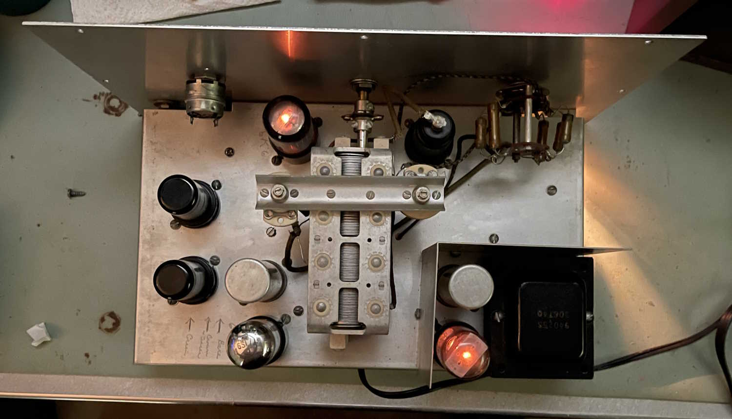
Inside was the normal array of wax-paper poppers and drifty carbons.
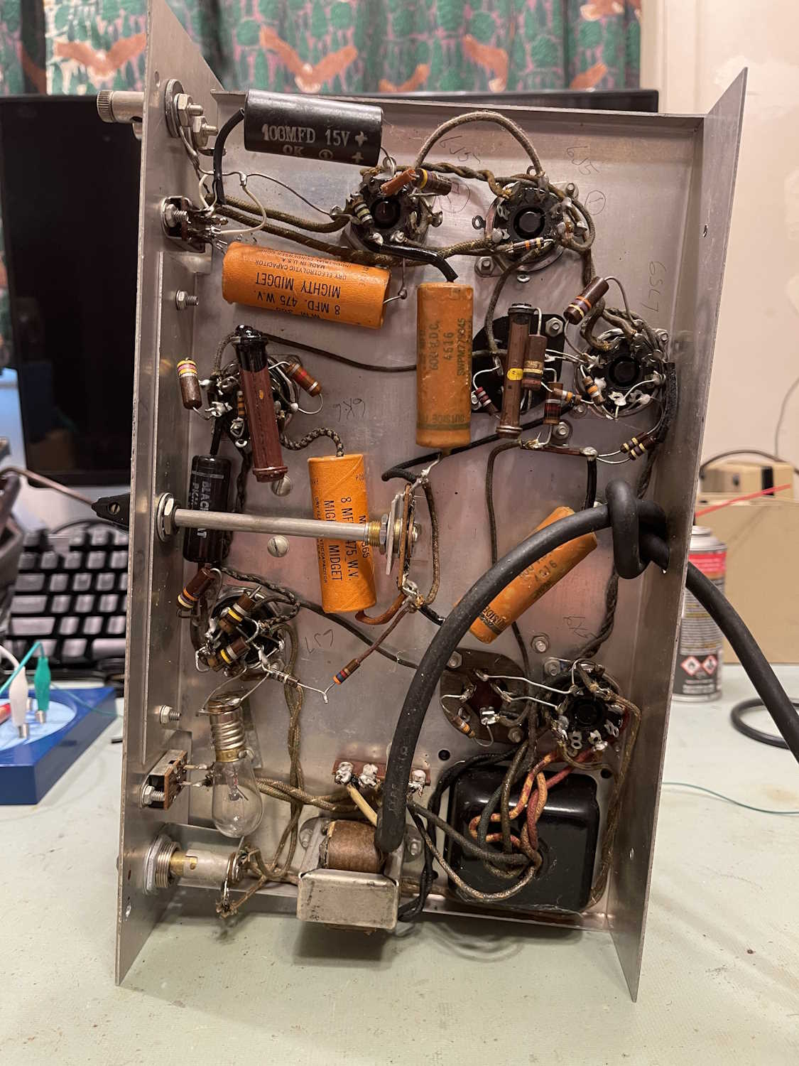
Pretty much everything in here had to go. And it did.
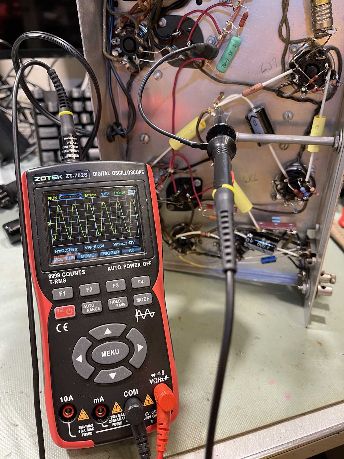
After some checking and corrections, I brought the unit up:
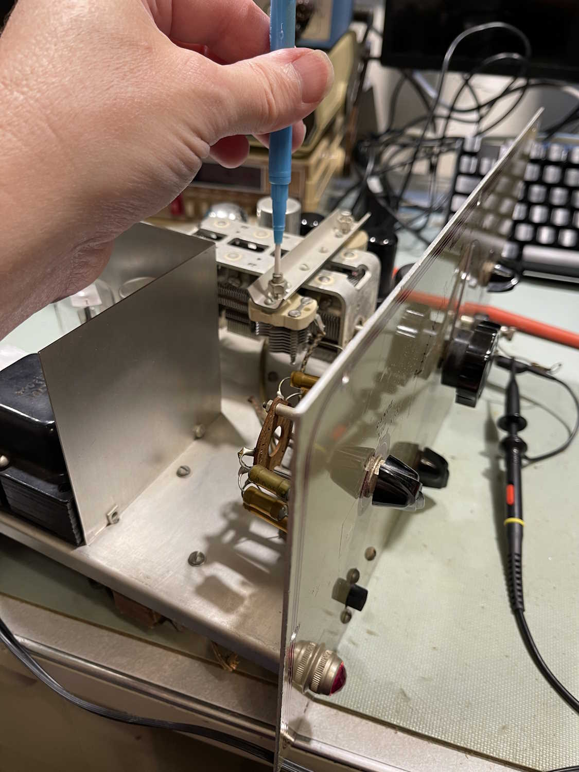
Inside, there are two small trimmer capacitors that you need to adjust to bring the frequency in to something useful. The manual suggests beating the device against line and doing some other stuff, but the magic of a good scope and frequency counter allowed me to adjust the device right in. I chose 400Hz as the adjustment point, as this is probably what it would have been used at during it’s life - 400Hz was the test frequency of choice before 1kHz was settled upon.
And that’s it. The device is buttoned up and working as expected for a device of this era.
The rebuild process
As stated, this device had a lot of work done to it, and had some small parts changes. One resistor was a pair with a higher value, most likely to drive the oscillator’s signal down in order to get rid of the flat bottom. This worked, but as the device aged the problem re-appeared and only a rebuild would solve it.
Selecting parts was fairly straightforward, except that some of the resistor values were harder to get than others in the tolerances I wanted. 820Ω, 2.9kΩ, and 3.9kΩ proved to be a little difficult to get in a 1/2W rating that wasn’t carbon film. I eventually found these, however, and installed them during the rebuild.
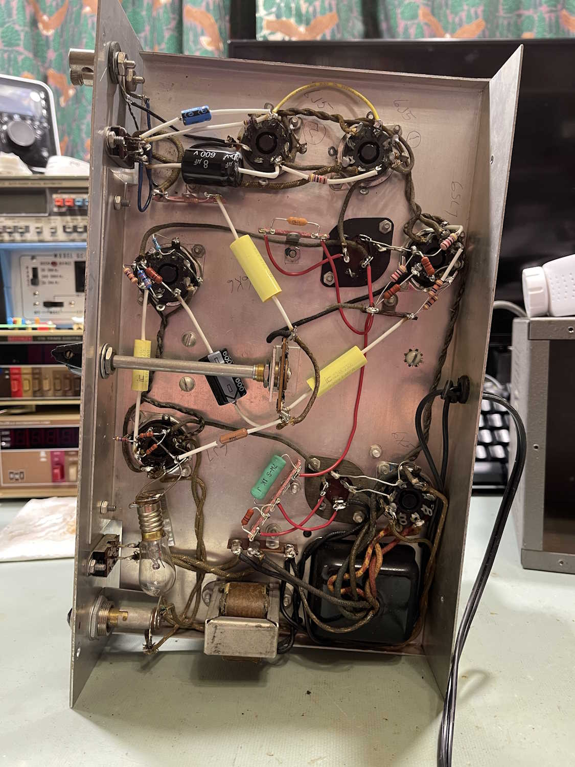
The filter capacitors were good here (for now!) so I left them alone, but moved the parts that would have attached to them off of the lugs. That way, if the filters need replaced (and they will!) it will be much easier as the only thing on them is wire connections. Everything that was on them is now on terminal lugs.
I ran into a couple of issues during the final check, but both of those were my fault.
First was two no-solders where I had removed things from a tie pin and didn’t re-solder the connection. That was easily taken care of. Second was the output Hi/Lo switch. I didn’t pay attention to the orientation of the switch and wired it opposite the wiring diagram. That, also, was easily corrected and just involved moving those connections around. After that, it tested fine and provided a nice, clean output. - after the standard spray of Deoxit in the switches and pots, of course.
Issues
During the rebuild, I noticed that the switch did not follow OEM wiring. There was a crossed wire on one of the terminals, which wasn’t indicated on the schematic. Why was this done?
Well, if you put the switch in the “Hi” position, you get a nice, strong output. You also overdrive the amplifier tubes and you get to about 50% and it starts to clip. This is in the sine output position, the square output position is of much lower input level and probably is fine. In the “Lo” position, you get nothing.
The “Lo” position connected the output to the cathodes of the amplifier tubes. There’s probably nothing there because there shouldn’t be anything there - the signal input is on the control grid of the 6J5 tubes. I’m not really sure what they were attempting to do here, but whatever it was didn’t work. I believe what the previous owner was trying to do with the wiring mods is actually get a useful signal out of the device. As I didn’t have much time to analyze the entire thing before smoke appeared, I’m not sure if that worked. Regardless, I wired the output as shown in the schematic.
The oscillator itself is somewhat not on-point, so the frequencies are off as you get farther away from 400Hz. It also has the lovely wien bridge issue of stalling if you change frequency quickly. If I ever feel like it, I’ll adjust the trimmers to the manual’s specs - but I don’t think this will help. It’s the way it is.
There’s a big issue, however, and that’s of the DC on the output. While there is a blocking capacitor on the output, the output floats around 110VDC as measured on a high-impedance meter. When you load it down, it approaches 0VDC. This is fine for tube devices, but a high-impedance load like a transistor circuit isn’t going to like that. So…this unit is not going to be happy in a solid-state world, or rather the solid-state devices aren’t going to be happy in it’s world!
That’s pretty much it. As stated, the device appears to be working as designed. I may revisit this unit at some point in the future, but it doesn’t necessarily have a place on the bench other than as an artifact.
The entire Heathkit AG-7 rebuild series
Stuff I brought home from Butler 2023 https://wereboar.com … uff-from-butler-but/
Part 1: Observations https://wereboar.com … part-1-observations/
Part 2: Testing https://wereboar.com … ator-part-2-testing/
Part 3: Diagnosis https://wereboar.com … or-part-3-diagnosis/
Part 4: Repairs https://wereboar.com … ator-part-4-repairs/
Part 5: It needs everything! https://wereboar.com … nna-need-everything/
Part 6: Removing everything https://wereboar.com … -removing-everthing/
Intermission: That’s not right! https://wereboar.com … ion-thats-not-right/
Part 7: The Rebuild https://wereboar.com … -part-7-the-rebuild/
Part 8: Finishing up https://wereboar.com … up-and-final-checks/
Part 9: Final Thoughts - You’re reading it now!
There’s a Viz WP-705, another Hallicrafters S-38C, an Eico VTVM, and a big TRF radio on the way. Stay tuned!
Previous part of this series: https://wereboar.com … up-and-final-checks/