A Simpson 715 AC VTVM Part 2: Attempting to fix the no zero issue.
Thursday, January 15, 2026 at 11:57:19
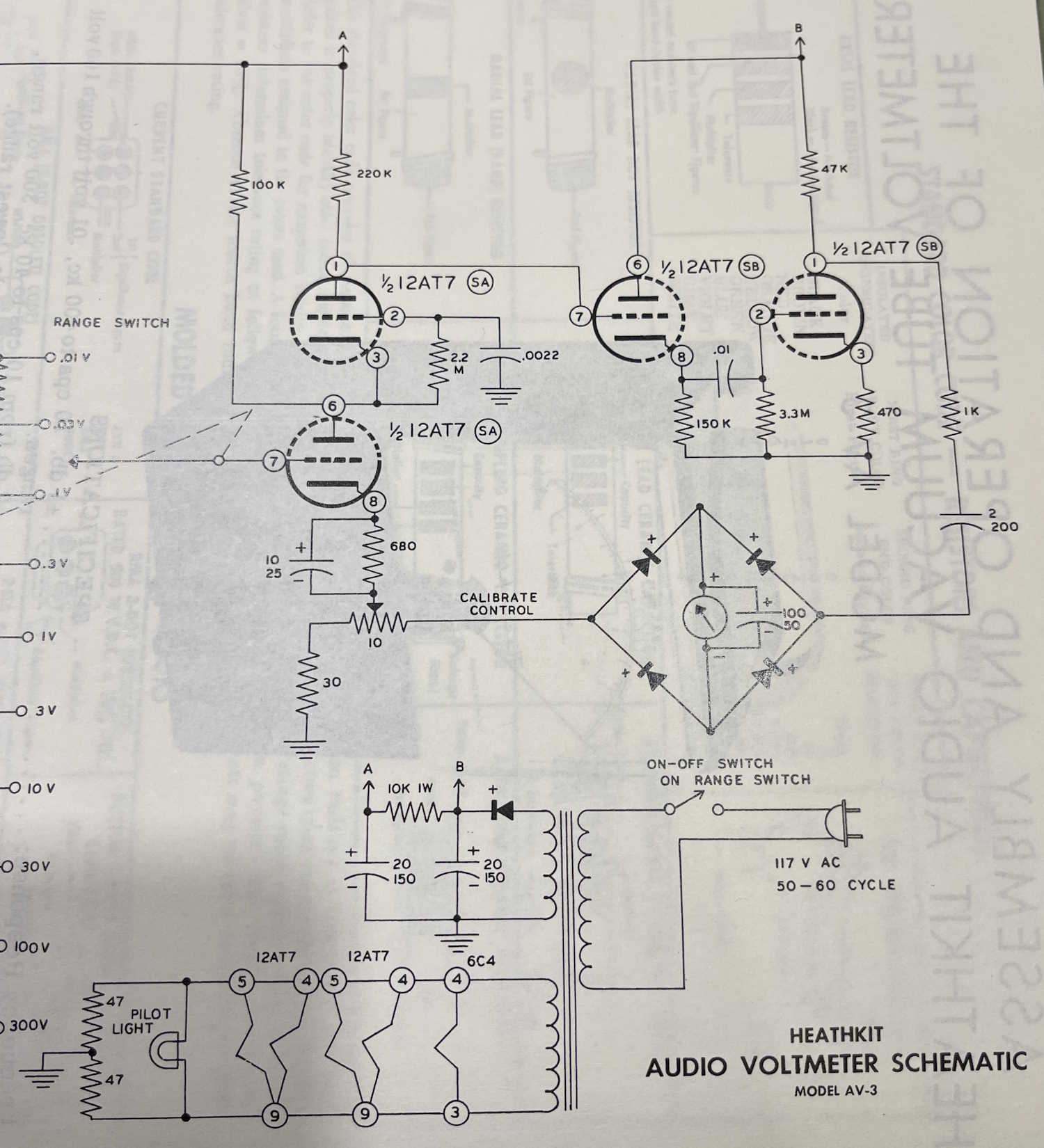
In the last part, we determined that this device was nothing more than a rebadged Heathkit AV-3, so documentation beyond the simple schematic was definitely available - including the tube voltages chart. That goes a long way towards an attempt to make this device work.
The Simpson 715 is a dedicated AC voltmeter in a small package. It’s not necessarily of the greatest use these days, but the package is kind of cool, so I decided to give it a go. It works, but won’t zero fully.

There are a number of capacitors in this meter, and some in the meter driver circuit itself. But for the most part, there are a number that must be replaced for continued operation, so I’m going to go ahead and get those replaced before continuing - and perhaps that will fix the zero issue.
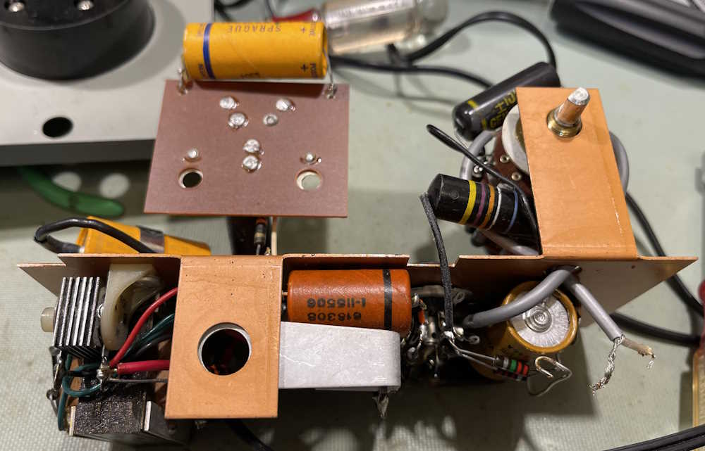
For this part of the issue, the following capacitors (identified by a yellow box) will be replaced:
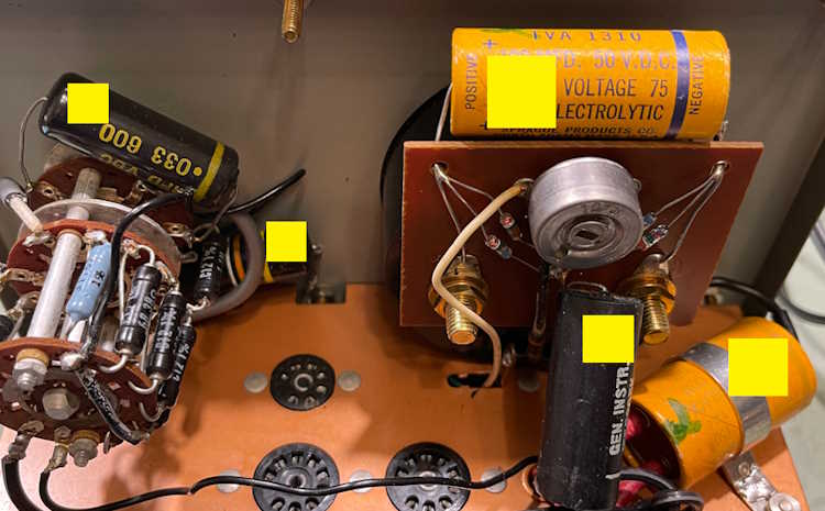
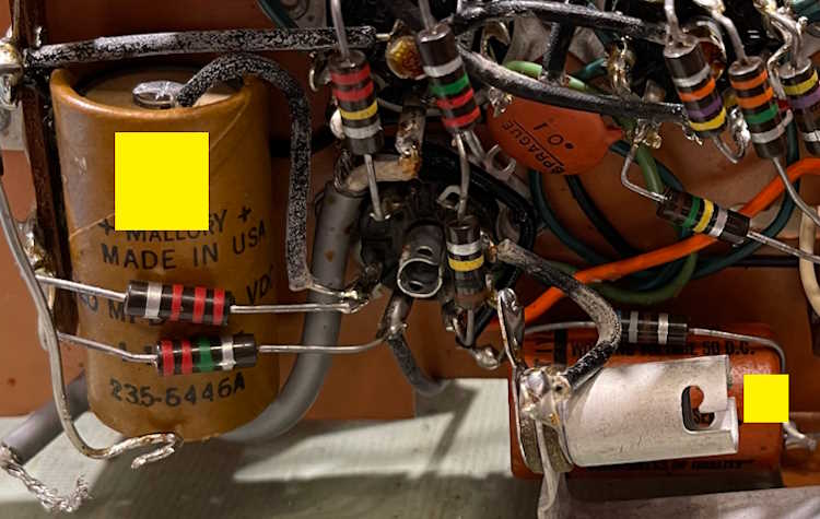
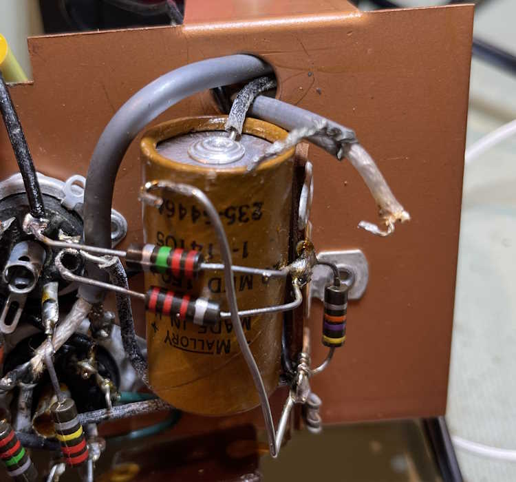
For the most part, these will be like for like parts, same value and voltage, except for the filter capacitor. This one is 150VDC, but it’s going to have to be higher voltage if I want to use this thing. Why? This little guy.

This selenium rectifier will need to be replaced as well. The problem here is that for a brief moment, the voltage on the filters is the rectified line voltage minus the voltage drop of the device. This is because until the tubes are asking for current, there’s no drop on the power supply divider resistor, and the full voltage appears on the capacitors. This isn’t a problem for a selenium device, which has a voltage drop in the 10s of volts. But, for a modern 1n4007, you’re going to have the full rectified voltage on the parts. It’s imperative to take the voltage of the filters up to a value that can withstand that.
Older parts may have also seen this higher voltage, but those old filter capacitors could withstand surges due to having thicker dielectric material and other construction quirks that we don’t use anymore. For this device, I’ve chosen 250VDC parts instead of 150VDC. I’m not going to replace the selenium rectifier until the device works, but that will be a future part of this series. For now, let’s just replace capacitors.
In order to do so, the unit has to come apart. The chassis is connected to the meter face at 6 points:
2 on the input terminals, these get unsoldered and removed for a cleaning bath.
2 on the meter itself, these unbolt and the board slides back.
1 on the switch, this is a nut that comes off.
1 on the pilot lamp, another nut that comes off.
Knobs, pilot jewels, and terminals all go in the ultrasonic bath for a much needed cleaning, and the face is left in an easy to clean state as well.
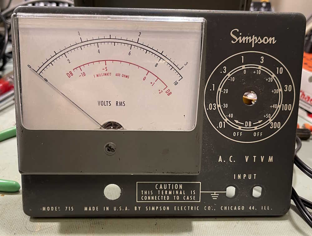
The meter itself is interesting. This being a Simpson device, they made their own meter movement and specified it be calibrated in a certain way:

We’re left with a chassis.
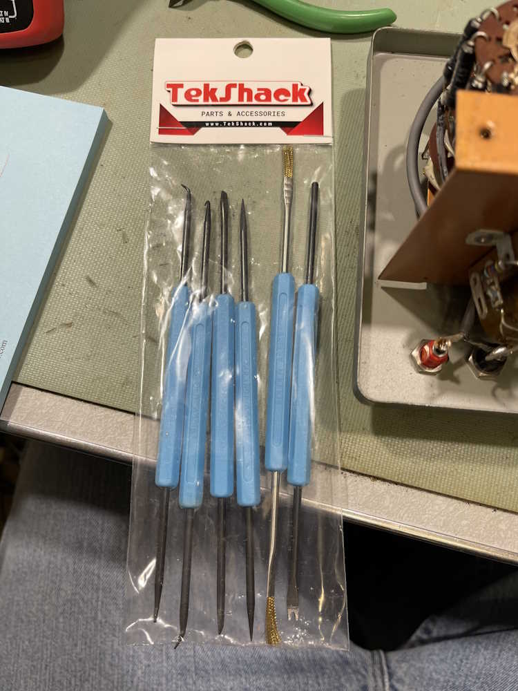
This is mostly just an exercise in delicacy, removing parts from old terminals. I get to use my new solder pick set here!
The big 0.033 on the switch goes first. This type of part tends to crack and leak. For some reason, I didn’t take a picture of it before coming off…
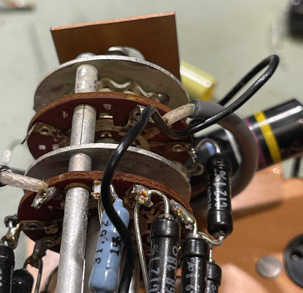

I may take that back off and put some ’sketti on it.
Next is that bumblebomb you can see behind the switch. These also crack and leak, although this one doesn’t seem to be one of the oil-filled capacitors. (By leak, I mean they absorb moisture and change value.) It’s not across the line, so no safety cap needed here.

I try to reuse the old tubing where possible, but some new was required.
Next is an electrolytic. A new part, much smaller than the old, goes in.
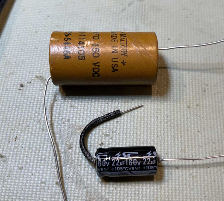
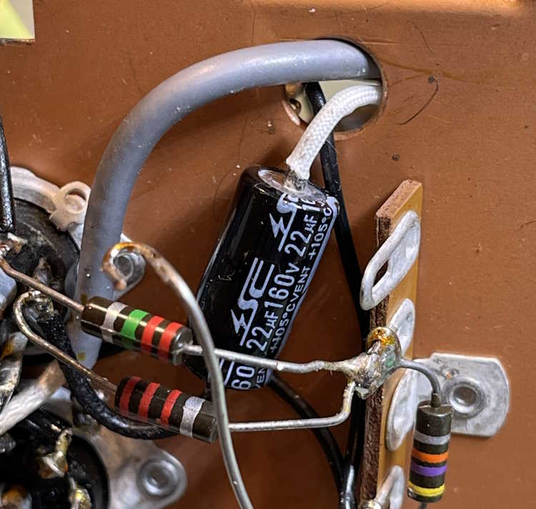
It never ceases to amaze me about the difference in sizes. Sure, the old ones had some advantages, but still…
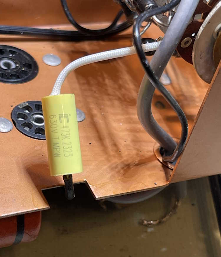
The next one has to wait a while, but here is the part that will go in. Similar size comparison:
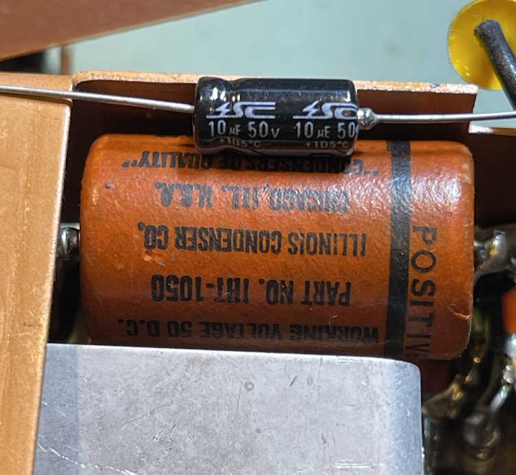
This part has a 680Ω resistor across it, and I’m going to replace both parts at the same time as the resistor is soldered directly across the capacitor’s leads. There’s also a 30Ω resistor after this pair that will get replaced, as all of these are directly on the meter legs.
I’m currently waiting on some parts to arrive and will install those when available. Stay tuned for part 3!
Next part of this series: https://wereboar.com … acitor-replacements/
Previous part of this series: https://wereboar.com … simpson-715-ac-vtvm/
Wrapup and final thoughts: https://wereboar.com … -and-final-thoughts/