Checking out some recent acquisitions - #1
Tuesday, January 6, 2026 at 12:58:44
This is going to be the first post in a seldom-series of equipment checkout posts. I’m going to take the unit apart, see if there’s anything that would prevent it from being turned on, do some basic “look here” things, and then turn it on.
This first post is two late year purchases, one from the Cleveland hamfest, the other from Fort Wayne.
This first one comes from Cleveland, and is a standard two-tube capacitor analyzer with an added headphone amp so you only needed one instrument on your desk. It probably designed for a set of high-impedance headphones of the WWII surplus variety, and much of the unit is built from surplus parts.
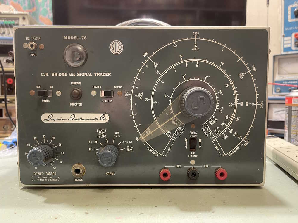
This was made by the Superior Instruments Company of New York. It’s in decent enough shape for the age. It’s complete, and has little damage to the front panel - but is in dire need of a cleaning.
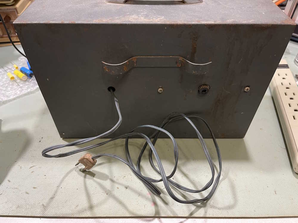
The back of the unit is rougher, but would most likely clean up nicely with a good scrub. We don’t even get a cord grommet here. The power cord itself is a nice gray-blue that matches the case, but is quite rock-hard at this point.
We don’t even get an underwriter’s knot here, the cord is just draped across the chassis with no thought as to how it affects the circuit.
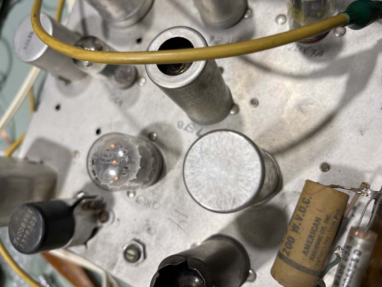
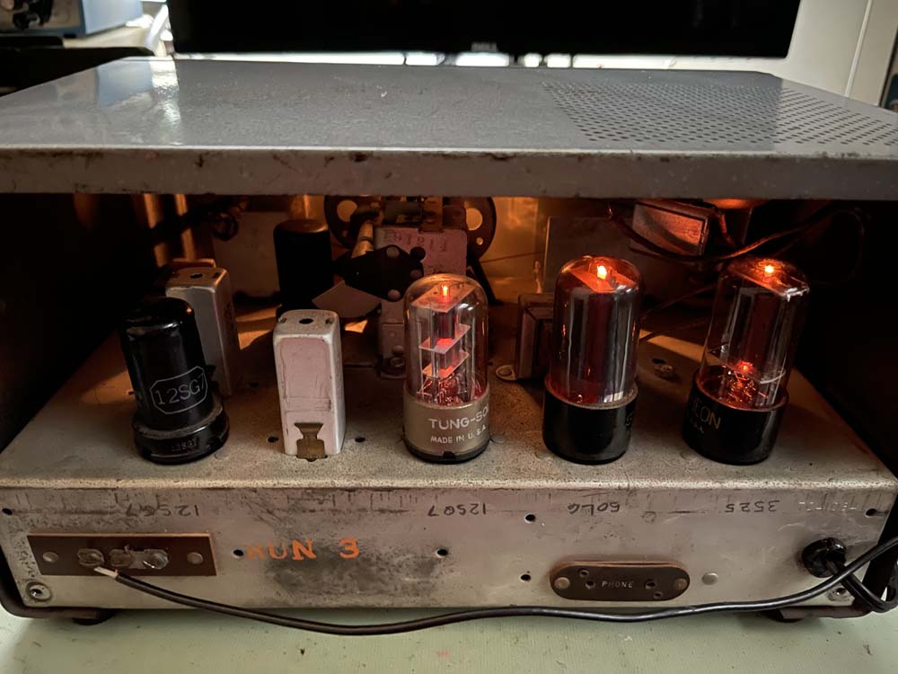
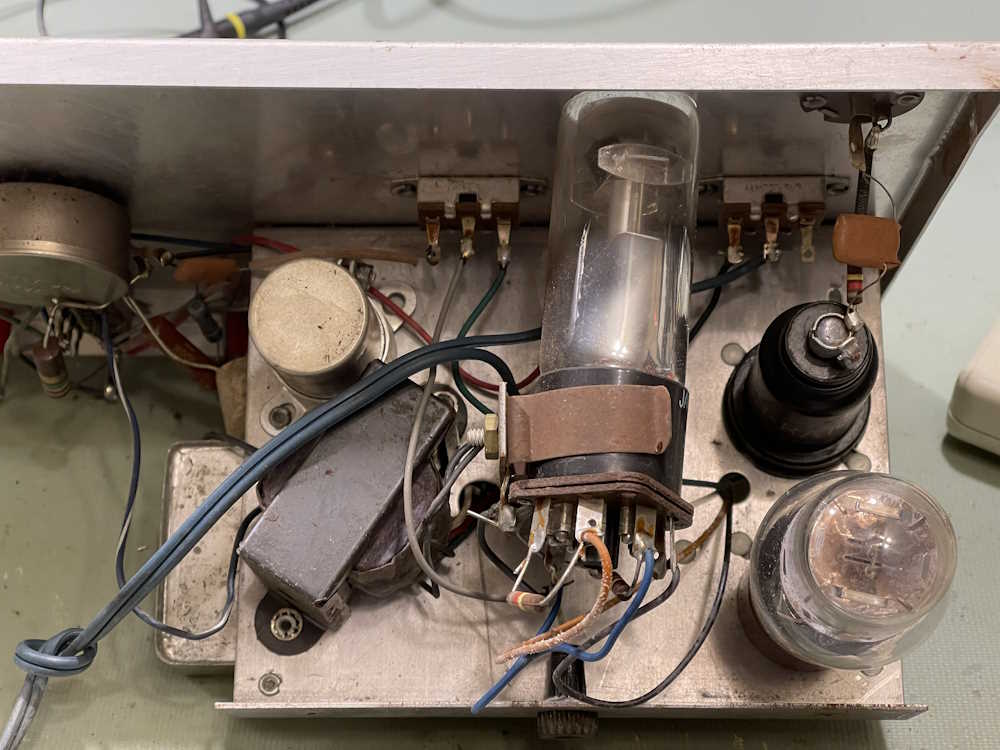
The chassis is about as cheap as you can get. A partial internal contains almost all of the components and tubes. Tube complement is:
1626 RF Triode being used as a diode (!)
VT-153 (12C8) being used as a headphone amplifier
1629 Magic Eye

All of these are mil-variants, which suggests they had lots of cheap surplus tubes. The triode is of particular interest. The manufacturer tied the control grid to the plate, making a diode out of the device. This tube also has a lower heater current than actual rectifiers, so they could use a smaller transformer. A way to use up what most likely would have been very cheap tubes that were of little use otherwise (the 1626 is a very low gain RF amp,) and as a way to use a cheaper transformer. Cost-reduced all the way.
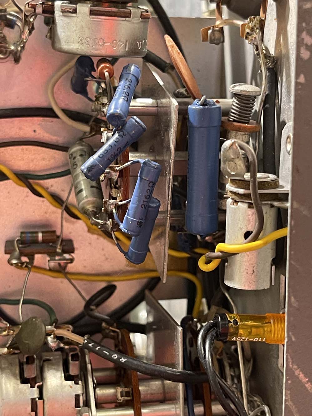
The bottom of the device contains most of the leaded components of the unit.
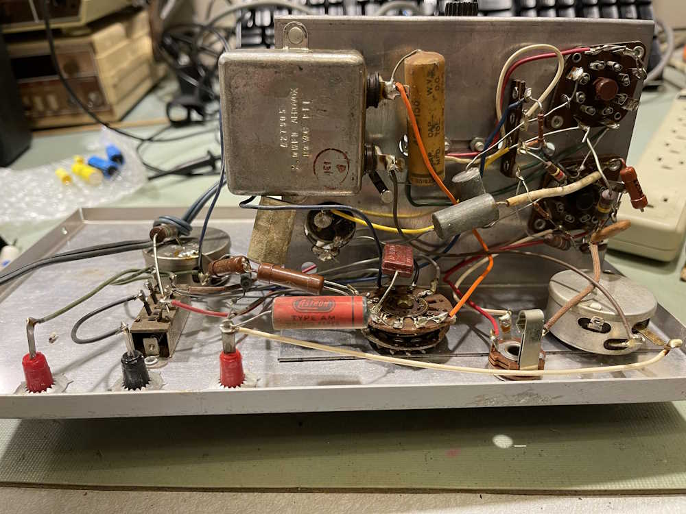
There’s probably some surplus here as well, especially those silvery capacitors with no other markings. Of special interest is that big motor starter capacitor to the left - it’s not even marked on the schematic. I also like the red Astron part in here, all by itself.

Speaking of the schematic:
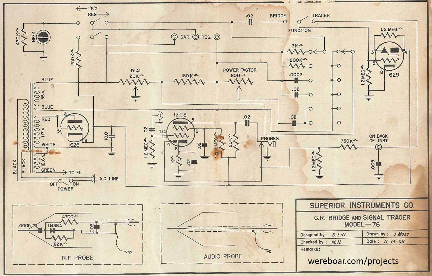
The device I have and this schematic only agree so far as “yes, there is that type of part in that circuit.” Not much else does - it looks like Superior probably used whatever they could get their hands on that was close enough.
Note the 2.0μF motor starter capacitor isn’t on the schematic - it should be connected to the power factor control. Who knows if this was omitted, changed, or added after the fact. Considering this was as cheap as could be, I would guess that the person who drew it was trying to be cost-effective, but it was found out later that the circuit didn’t quite work as planned. Other capacitor analyzers I have with a power factor measurement have a big capacitor in that circuit, so…whatever. There it is.
I don’t see anything that would prevent this from working, so let’s plug it in and see if there’s smoke!
The eye tube lights up. It’s acceptable, and can be seen in a lit room.

There’s no other power indicator on this device. I guess you really don’t need one.
DC on the power supply is kind of bleah, especially for having almost no current draw. This may be a symptom of using the wrong tube in the wrong place, or a bad filter. I didn’t stick a new filter in here, that may happen later. This is just to see if it works.

So, let’s put a capacitor on it. I chose a 8μF “Mighty Midget” removed from a previous rebuild. It’s gone quite high, so we should see something well in excess of 8μF.
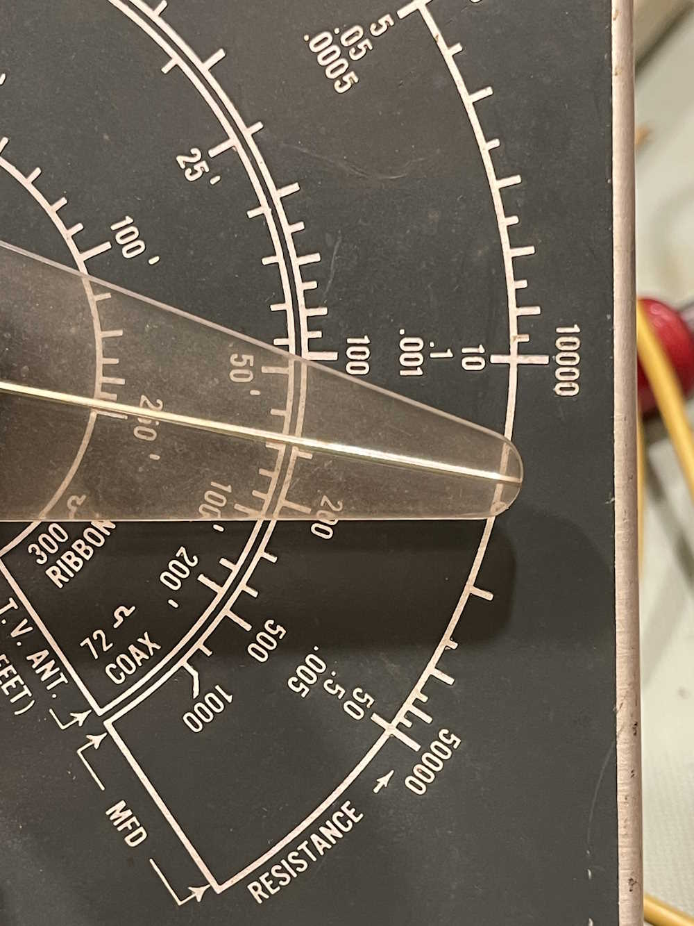
The device seems to indicate this is about 14μF and change - we’re reading the top portion of the middle scale.
Let’s get a second opinion.

The second doctor disagrees with the first. However:

Doctor #3 agrees with doctor #1.
So, this device is probably as accurate as this type of device can be. It goes back together for later potential rebuild.
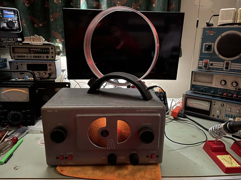
Next up is another IG-72. I purchased this at Fort Wayne, mostly as a spare for the one I already have. It’s in ok shape.
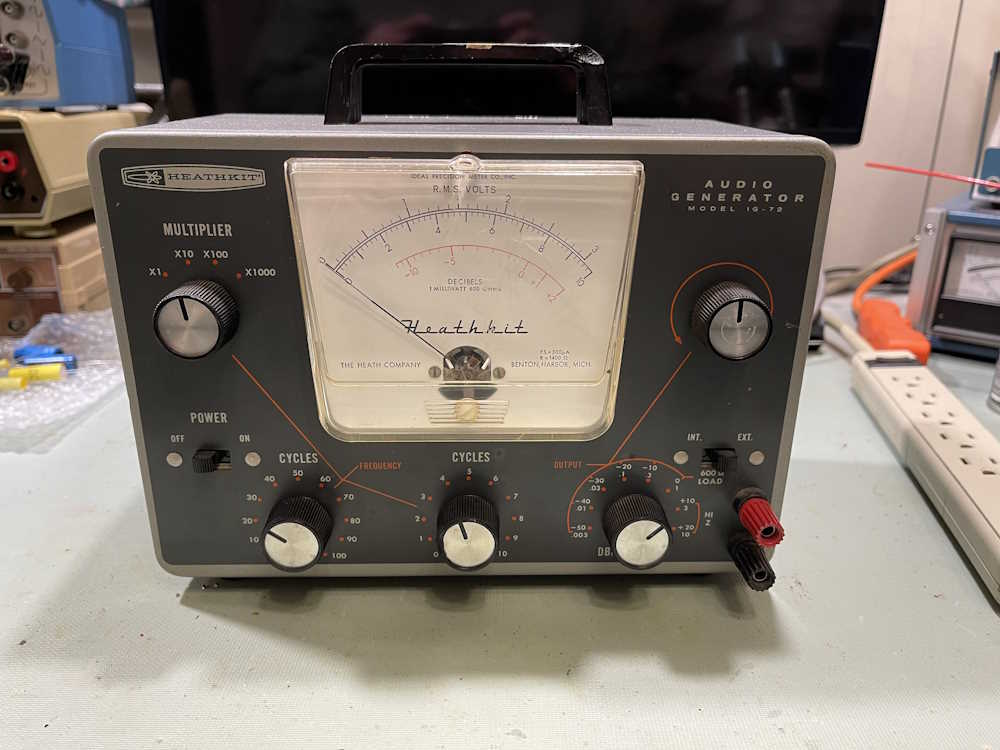
The back is likewise in not terrible shape, and has some interesting markings.
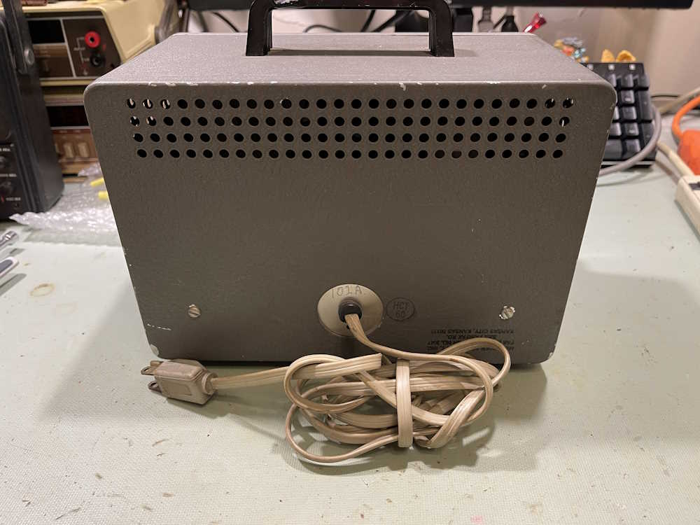
Of note is the fact that this one has a grounded cord, whereas others I’ve seen do not. There’s also the stamp in the corner.

It says “MEISINGER BEECHCRAFT, INC.” and was apparently part of their repair area test equipment. That’s really cool, this one has a history.
It was certainly used, but not abused:

It has the obligatory soldering iron melted spots. It was also millerized - whatever that means.
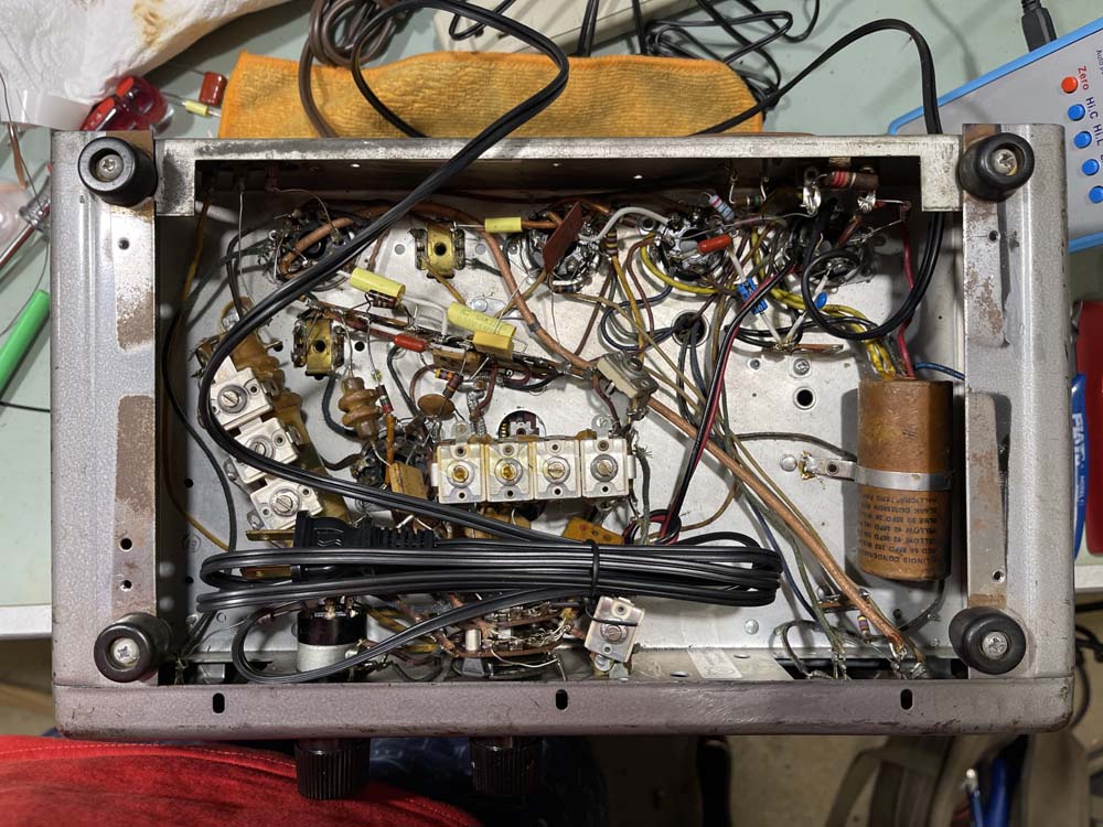
The inside is clean, but dusty. The transformer is a bit loose.
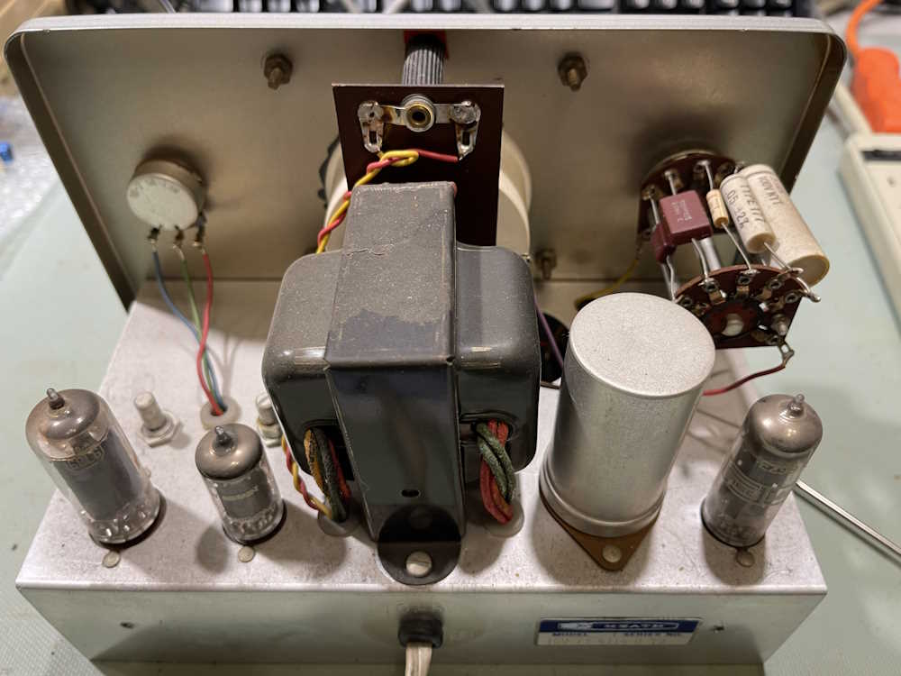
Tube complement is:
6X4 Rectifier
6AU6
6CL6
The CL6 and AU6 form the oscillator and output amplifier pair. It’s a standard Wien bridge oscillator with a light bulb in the middle as a PTC resistor. Two of the tubes are most likey the original Mullard tubes, and one is an RCA.
The bottom looks to have been factory built.
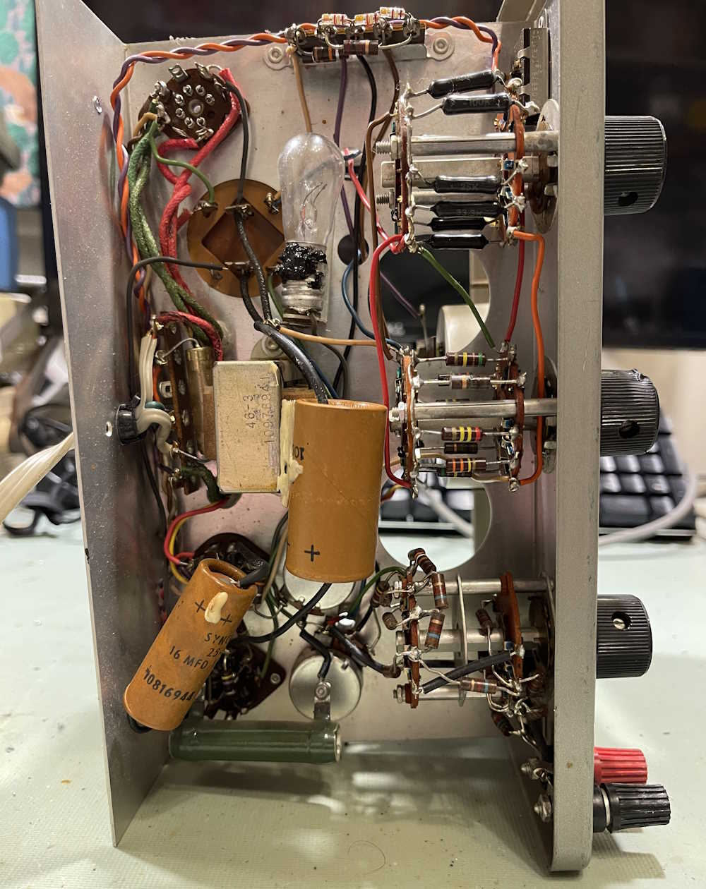
The bulb was goop’d in, probably to keep it from vibrating out during use in a running aircraft.

Nothing sticks out as preventing operation. Let’s pull the rectifier, as these liked to arc across the cheap socket.

Nope, that’s good. Time to plug it in. Power is applied. We have tube lights.

The needle comes up, and look there - this one still has it’s little red film for the power lamp.

The DC on this one is so clean, I can’t get anything off the power supply. The output is equally clean.

The signal does distort a little at the bottom of the wave when it’s turned up to full output, but that’s a known Wein bridge issue. I can dial it back a little and probably be fine.
That’s all for this one - other than some cosmetics, this device is fully operational and seems to be in great shape.
I’ll have more in this series as I pick up more devices. Stay tuned!
Next part of this series: https://wereboar.com … -ps120-oscilloscope/