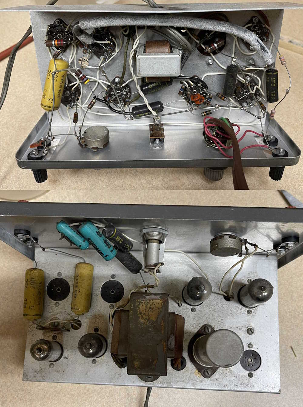
Before you can put new parts in, you have to take the old parts out. So I did. I decided to just pull everything, clean up the connections, and replace everything all at once. Would I suggest doing it this way? No, not unless you’ve got a decent amount of experience building this kind of device, you have a decent amount of experience in general, or you’ve done this before. It’s better to replace each part individually - but since this chassis was kind of sloppy I decided to do it all at once.
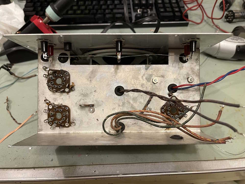
To be honest, this wasn’t put together the best. Some of the components were installed properly, leads through the connection holes and wrapped to make a mechanical connection first. Others were just tacked on and pulled right off with the application of a little heat. Others were simply run willy-nilly with electrical tape and whatever was available. I have to assume that it had been repaired a number of times in it’s past. Hopefully, now that the chassis is clean it will look a little better going back together.
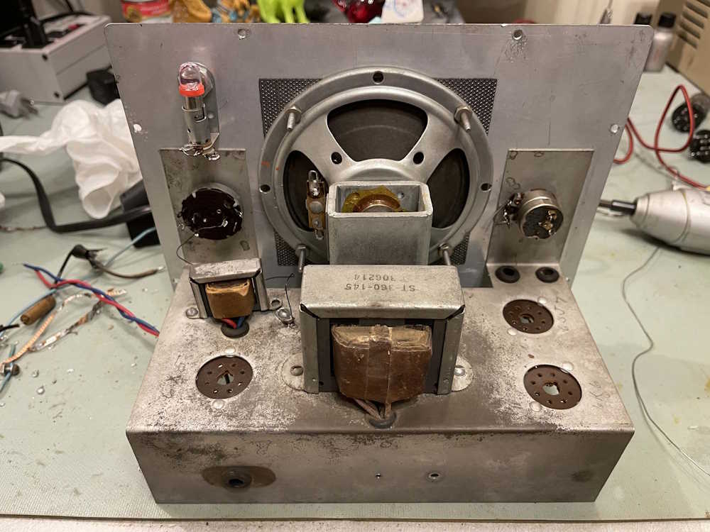
There were a few things left in. Transformers were left connected in some spots, and the jumpers that run around some of the sockets were left in place. All other things were removed.
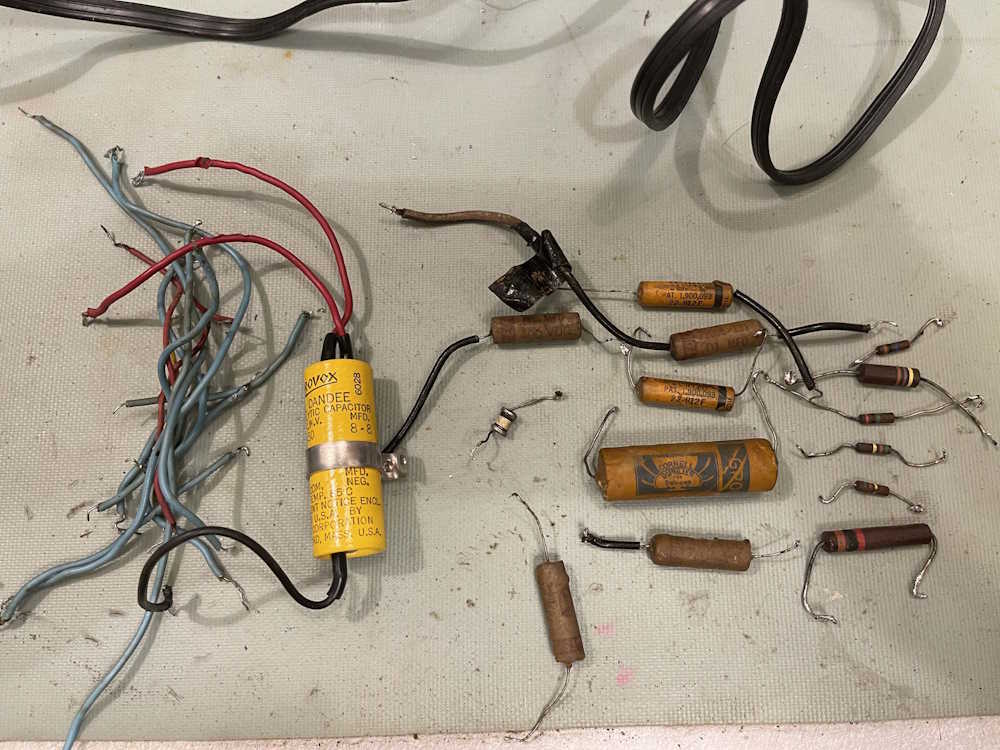
There are surprisingly few parts in this thing.
I’m planning on measuring some of them later to see how far they’ve drifted, but I did decide to check the electrolytic to see if it was bad or good.
Yeah, they’re ok. Well within the -20/+100% tolerance, but the ESR is creeping up. They’d probably be fine for a while longer but there’s no need to keep them in there.
Something of note here: If you look at the removed parts, right beside the dual-section electrolytic is a little white tube. This is C1, which is supposed to go across the input terminals. Parts list says it’s a mica capacitor, and the drawings seem to show a mini postage stamp. That’s a ceramic tube capacitor - was that original, or did it get replaced at some point in it’s life? It’s old enough that it could be original, but who knows.
Next thing to do it start rebuilding. I may wait a while before I get to that, depends - if this is a rainy fall, a suitably wet Saturday may see this thing put back together. I may also just build each stage on it’s own once I get some suitable wire, and we’ll start with the power supply.
I decided to sit down with this device last night - the intention wasn’t to fix it, but to clean up the pilot lamp wire and get it prepped for a little more troubleshooting this weekend.
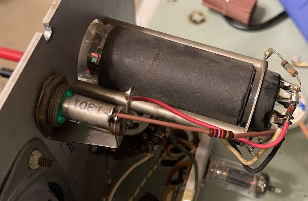
Whomever added the pilot lamp did a great job mechanically, but a terrible job electrically. I didn’t take a picture of the “before,” but this is the “after” wire that was removed:
The pilot is tapped off the filament voltage for the eye tube, and all filaments are in parallel. The tube socket for the eye has two eyelets for each pin, so you can do exactly this - but the person just kind of tacked the wires into the holes with a big blob of somewhat cold solder. It worked, but there was pieces flying everywhere and enough solder to do all the pins. I removed that, wicked it clean, re-seated the filament wires for the tube, and continued with my cleanup.
I’m using an LED #47 replacement to keep the current draw low - the device wasn’t designed with a pilot in mind so I want to keep the transformer happy. A 2.7k resistor of the proper vintage and some small heat shrink does the job - the resistor is needed because the LED bulb is blindingly bright, and I wanted to cut it back to a more reasonable “I’m on but not lasering your eyes” brightness.
I probably should have J-hooked a longer wire on to the resistor and moved it closer to chassis to keep AC from flying around, but it’d not enough for me to worry about. There are other filament wires winding all over the place, the little bit of emission from the resistor isn’t going to do squat.
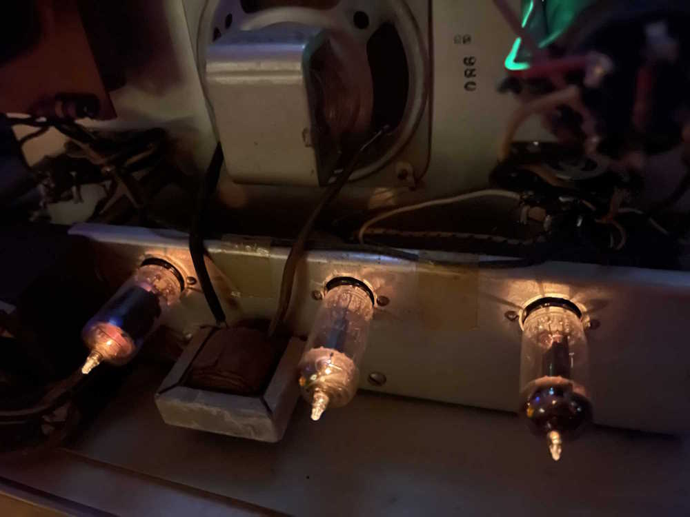
While I was sizing the resistor (I have a junk bin of older parts) I bumped the input 6C4, and the unit crackled to life. I finished up my resistor installation and hooked the signal generator up - 1kHz came blaring out of the speaker. Turns out the sockets are a bit flaky, which is not a surprise for a device that’s looking 80 years old square in the face!
The speaker is a bit rattley, so it (and the filters) will need to be replaced. The screen also needs to be knocked out, so I’ll do the speaker and screen at the same time - assuming I can find a properly sized speaker, that is.
Beyond that - and after a liberal dose of Deoxit to quiet the moving parts - the fire bottles are full of fire and the device is happily spitting out audio from a crystal radio.
A new cord, some maintenance, and this guy is going out in the main room to be used as a small amp. Strap on your cap gun and get your mask, the Lone Ranger is on soon!
Sometimes, you get a piece of equipment and wonder what they were trying to accomplish.
This Heathkit electronic switch (Scope Chopper) has some modifications - one of the channel inputs has been replaced by a switch, resistors, and a power outlet hanging off the back. Some tubes are missing. I have absolutely no idea what they were trying to accomplish here.
While replacing the potentiometer would be easy enough, the 12AU7 and 12AX7 amplifiers are gold right now. Kind of like putting new tires on a $50 car - the tubes make the device far more expensive than the $2 I paid for it.
For now, this will probably go in the spares bin in the event that I can get a better example to use with my scope.
I recently went to visit a former co-worker who had retired, and was moving. He said “I’ve got decades of junk from my ventures, if you want some come get it.”
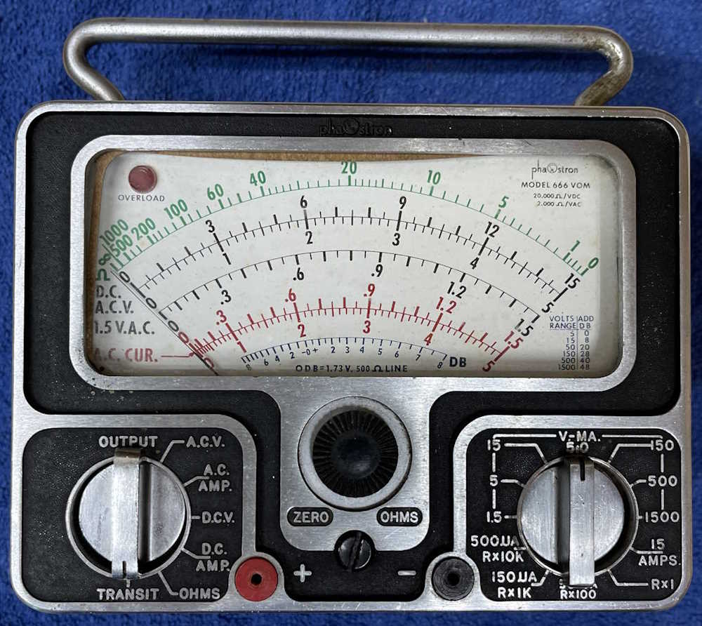
Well, come get it I did. In addition to boxes of 1980s ICs, a bunch of random parts, and some test equipment was this unusual example of a meter.
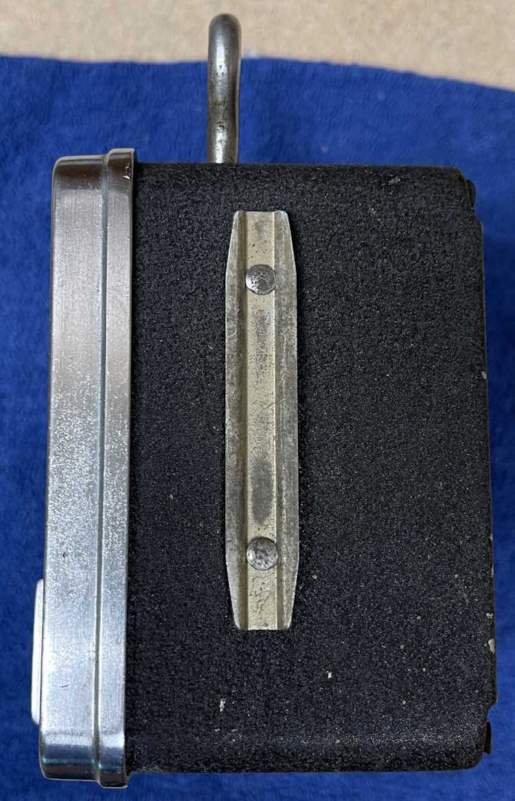
Phaostron, still in business, tended to make ruggedized meters for industry - and this thing is no exception. It probably would have had a case it slid into (long since dust) as evidenced by the slides on the side.
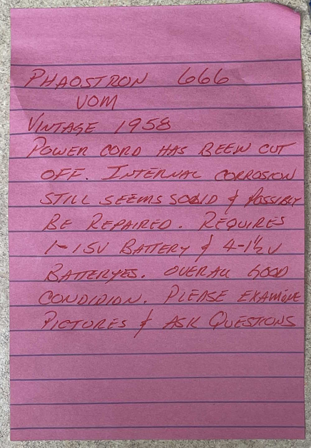
The person said that it was kind of messy inside, and this note was attached. It looks as if he had tried to sell it at some point in the past, probably at a yard sale.
And corroded inside it is. You can see it on the internals even before the case is removed.
It’s hard to see from the lighting, but the case is all brass - even the front, which is a solid chunk of die-cast brass. It was sold as being antimagnetic, which asks the question: what was this thing designed for?
The thing is simply packed with parts. All of the ranges are fused with their own specific size fuse.
But, as noted - it’s a mess inside. Corrosion everywhere. It takes a 15V battery, and a 4.5V mercury cell. None of those are available, but it looks like they leaked at some point in the past. Mercury cells leaking gave the same messy green crud as alkaline cells would, and this one certainly shows it. Also note the wax-paper capacitor tucked down in there. How you’d get to that is a question for someone else.
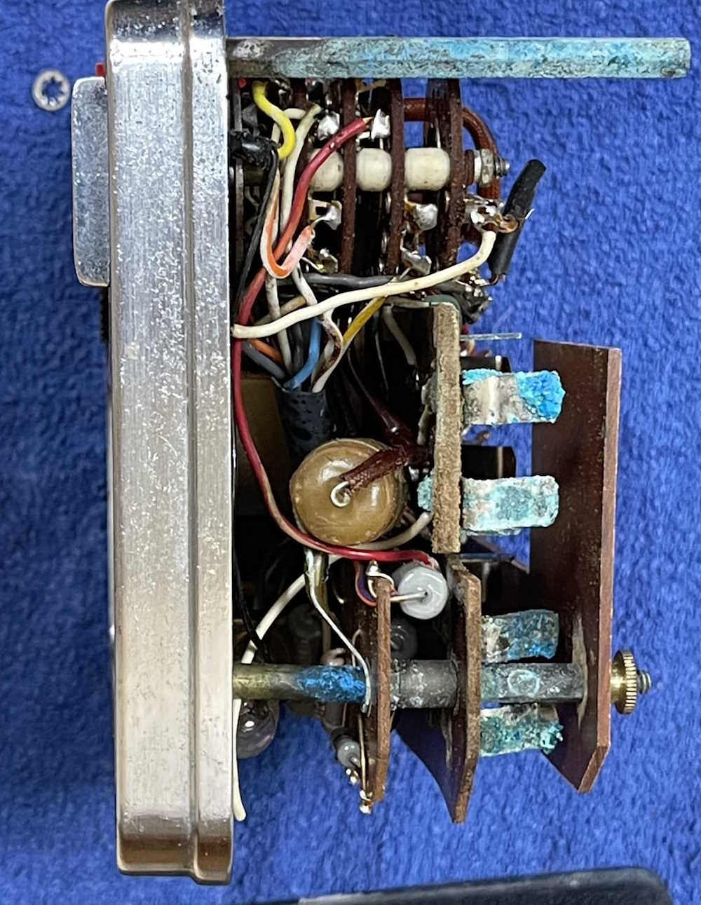
The other side reveals just as much packed-in parts.
One interesting thing of note - instead of trying to switch the 15A range on the front, the manufacturer used this fiber insulated disc to push a set of contacts together. While the fiber washer is long since passed it’s prime, it’s still an interesting example of how to properly isolate higher currents from the user’s fingers. Note all of the tightly tied cables - this thing was quality crafted.
So, what happens to this device? It’s supposed to have an illuminated scale, powered by the AC line. The power cord is missing, long since removed (or never attached?) but I can see the lamp in there. Perhaps I’ll disconnect and tie off the original wiring and just put some LEDs in there.
I think it would probably look good with low illumination, because at this point it’s probably not going to do anything other than be a display piece, a device that looks and feels like it’s come from the distant retro future. It sits quite happily on the display shelf, behind a small pocket radio of similar vintage.
The day couldn’t have been any more perfect for this show - it barely got above mid 70s.
However, the show was substantially smaller this year, which is something I’ve noticed about the regional shows as we get further into 2024. There’s just not as many vendors showing up. That could be because the economy is turning to crap - some of these guys just come to see friends and BS with people, the sales being a “hey I made some cash, nice!” side effect. The crashing economy also seems to have reduced prices - I picked up some things that would have been a lot more expensive just a few years ago (and still are being sold on eBay for outrageous sums!)
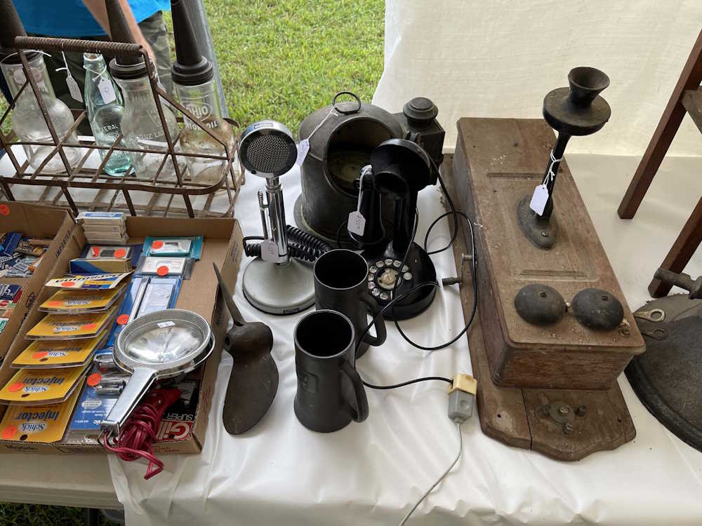
Regardless, there were still some things to be seen and had, and this show rarely disappoints. This is some of the good stuff I looked at this year.
A neat voltmeter with an IBM label.
A Sony multi-band radio sits among some other interesting devices.
An airband two-way handheld sits among some Heath equipment.
A battery tester. Odd stuff.
The seller said the markers were the best deal at the show.
An old old Buick car radio - full of tubes.
It's a Commodore Cornucopia!
A direction finder radio.
I didn't need it, but the little siggen was cool.
I swear there was at least 3 of these for every person on earth.
A common sight, a table full of random items.
Just parts. I took the RC tester in the upper right.
Many things. There was another tester in top the HP unit that I took.
This massive converter box went under your dash.
Old meters in lovely wooden cases.
An old National radio with it's band selectors.
A Wooden Weston with a hand marked scale.
Personal Portables. That sounds like a Jeopardy category.
I almost took the S38 for parts.
You'd never guess what I saw at the radio show. That's right, radios!
A speaker among the other equipment. I need to pick one of those up sometime.
It's all 10 dollars a unit. I took the Heath signal tracer.
Lots of old equipment always shows up.
More test equipment.
Some random radio gear and a tube tester.
A friend examines a rebadged Sony VTR.
.
Next show is either the Massillon show - if I can get to it, or the Fort Wayne show, which always rounds out the year for my fest-goings.
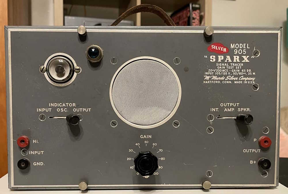
I was recently browsing a local antique mall for an unrelated purchase when I came across a booth with a lot of electronics. Near the back was some test equipment - this unusual signal tracer being a part of that display. It was cheap enough, so I picked it up, noting the name and asking where I had heard that before.
Turns out that this was made by McMurdo Silver, a company known for producing visually stunning and electrically over-engineered radios. I’m not going to go into those here, but there’s plenty of information online as they have quite the fandom.
This is just a signal tracer. It would have had a crystal diode probe at one time for tracking down audio in a RF signal, or simply following it through the amplifiers after demodulation. It does all the usual signal tracker things, like amplifies, gives you a visual indication via the eye tube, allows you to tap the plate and B+ of the final amp, etc. Nothing unusual here, other than the manufacturer.
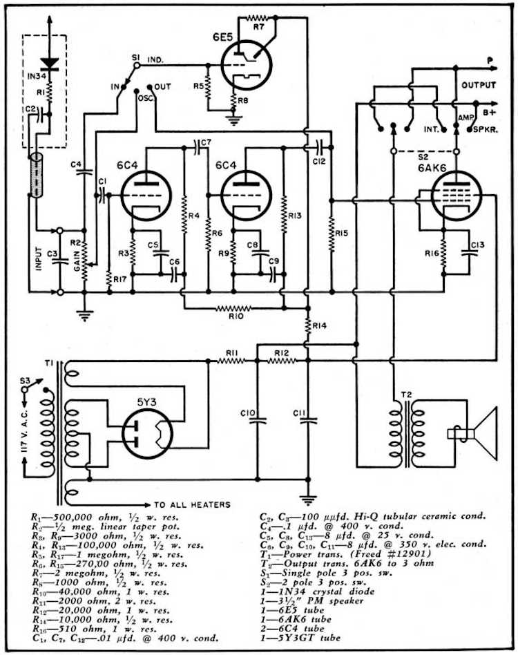
Tube lineup is pretty simple, consisting of a 5Y3 rectifier, two 6C4 amps, a 6AK6 power final, and the 6E5 eye. The 5Y3 is somewhat hard to get, and the 6E5 is unobtanium. I’ll probably try and pick up some spares at Findlay, if they’re available.
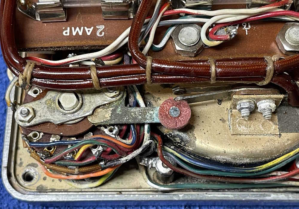
Beyond that, you can see a little of McMurdo’s over-engineering in this device as well. The lever function switches on the front are pretty stout for consumer gear. But the back is another story, the cord simply goes into a large hole where you could easily reach in and touch the transformer taps!
The front panel is sparse, but there’s an anomaly here. The literature for the unit shows a lamp above the speaker. This one has the lamp off to the side - but is it original? I have not opened it up to see how it’s connected. The schematic for the device doesn’t even seem to show a lamp!
I did give it a quick try. It lights up. There’s no hum of any sort, so I’m not sure if it works, but fortunately I have another signal tracer to check my signal tracer with!
I was sent some literature on the device, so if this is yours and you don’t want it here, or need attribution, poke me on mastodon.
There’s not much more to say about this device other than stay tuned - I’ll fire it up some weekend later this year and see what it does.
Well…either that or I’ll fire it up immediately after I wrote this post. No hum, but I get noise when I switch the output selector. I assume the speaker and output transformer are working, at least. There’s a dozen things this could be, so it goes on the bench to work with right after the other signal tracer gets rebuilt.
I did take a minute to investigate the lamp placement. It appears this was added after the fact, but not that long after as the wire type matches what’s in the unit itself. This will need some cleanup as well, as it wasn’t installed in the best manner.
Saturday threatened rain all morning, and that seemed to keep the crowds down this year - the roads were relatively clear on the way home. In contrast, last year was backed up for miles in every direction with people trying to get in.
We arrived fairly early, and some of the vendors hadn’t opened yet, but we wandered the aisles, had some Bourbon Chicken and Fried stuff, and managed to see it all. Most was just flea market stuff, but there was some cool things on site.
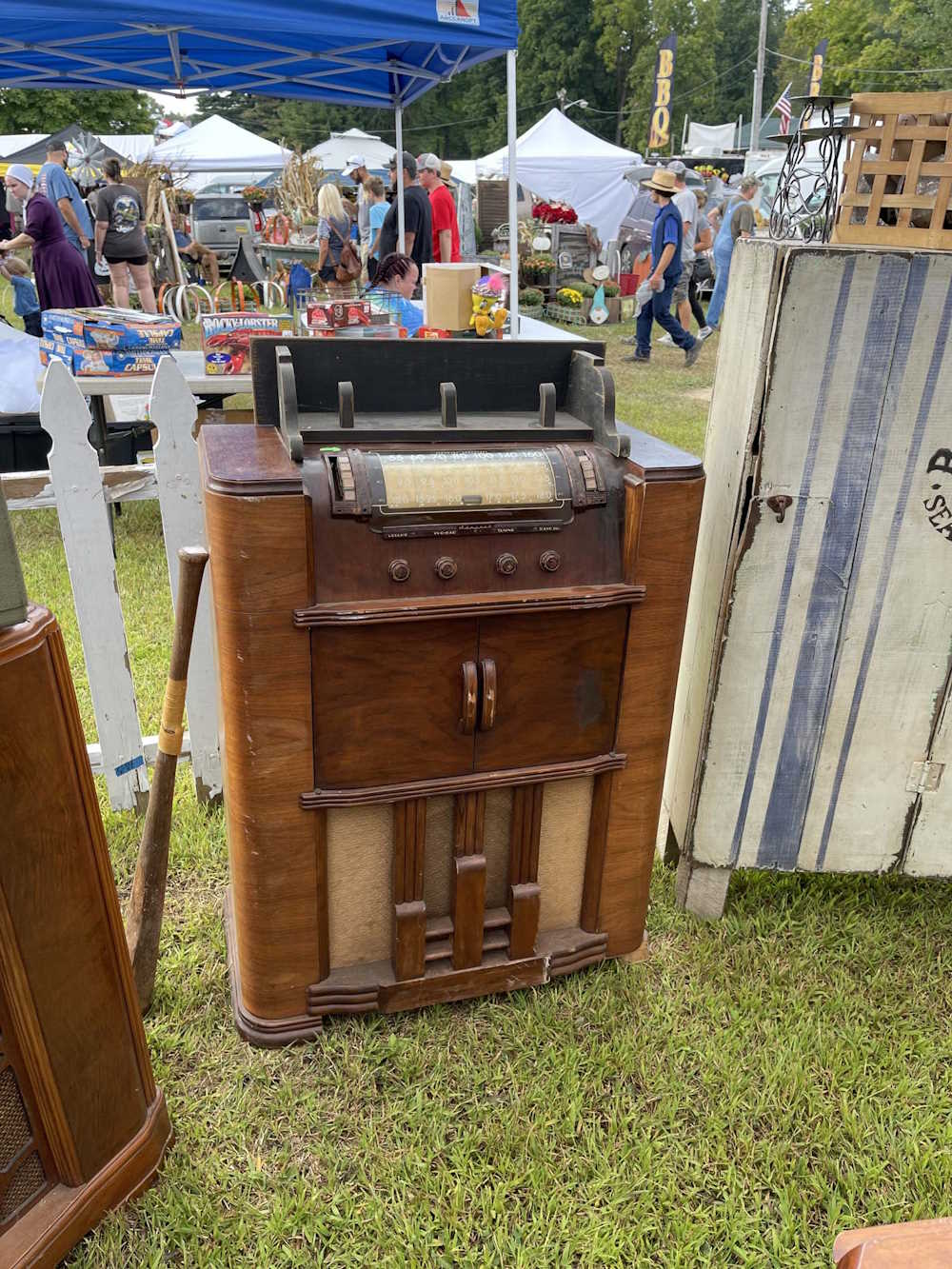
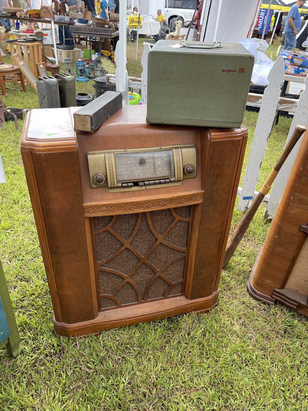
This Admiral console radio was in pretty good shape for it’s age.
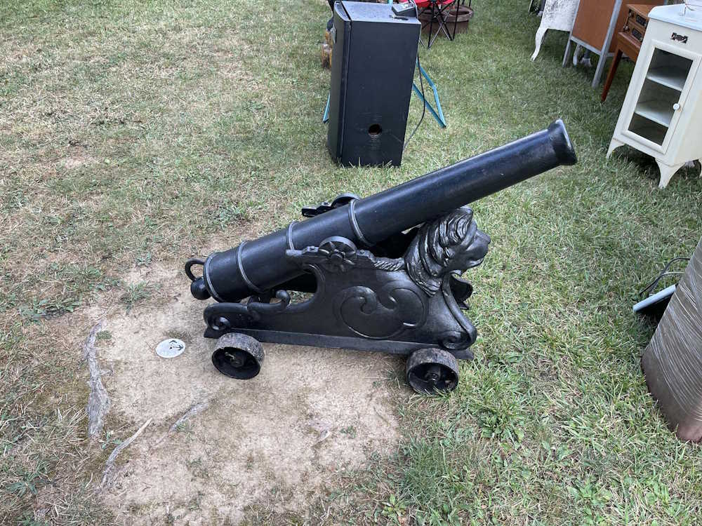
For your 1812 Overture re-enactments.
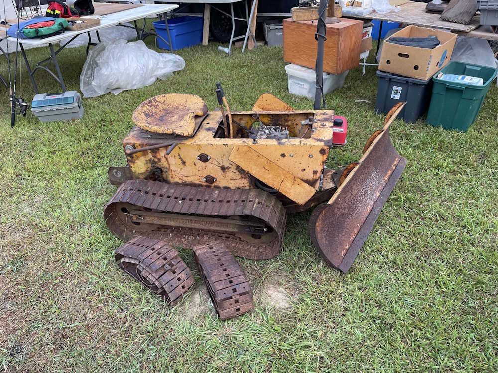
An adorable miniature bulldozer. It’s low, maybe this was for use in a mine? (No, these were sold to the general consumer as a small piece of equipment. There were other attachments for it as well.)
A nice looking Edison Home unit with crane and witch hat horn. Did not pull the top off to look at it.
A clear Aladdin Beehive, and a pink and clear Aladdin Corinthian lamp. They were priced appropriately.
A Ford Model T. Price: 29k
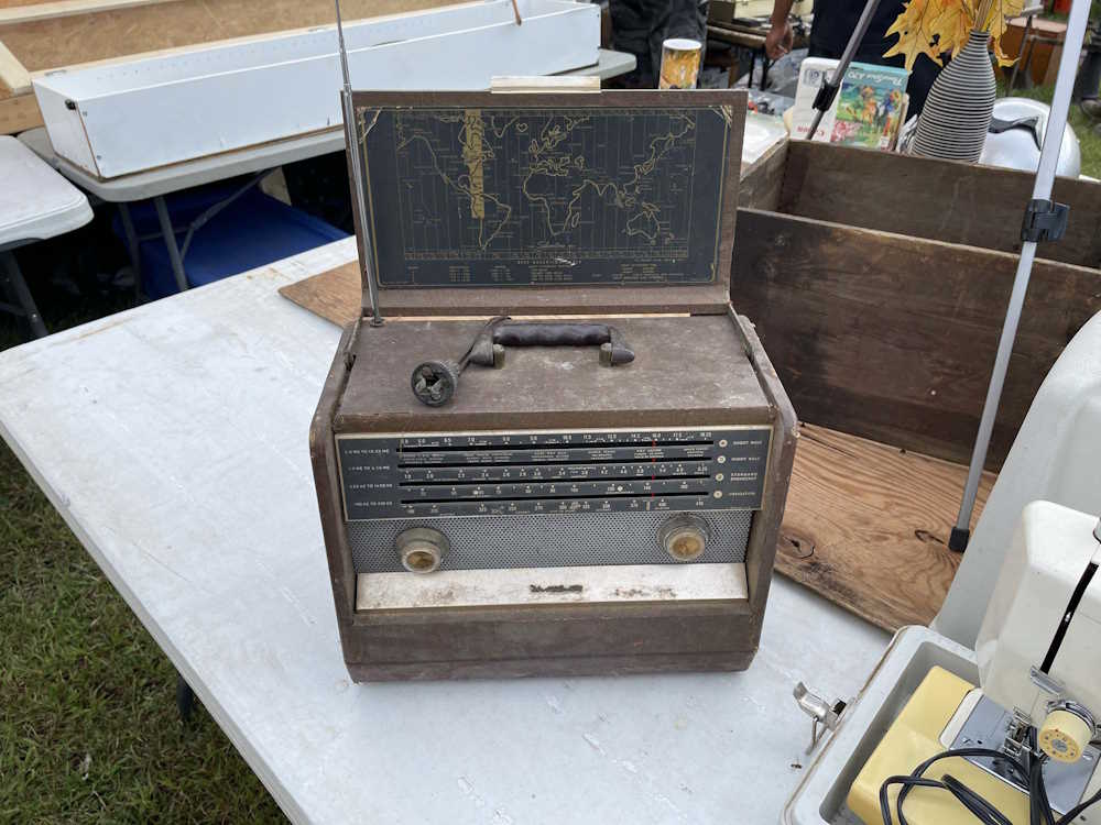
A Sears Silvertone Trans-Oceanic clone. It was in ok shape, didn’t see the inside.
A nice Silvertone console radio. The eye tube was inside, but was laying on the chassis.
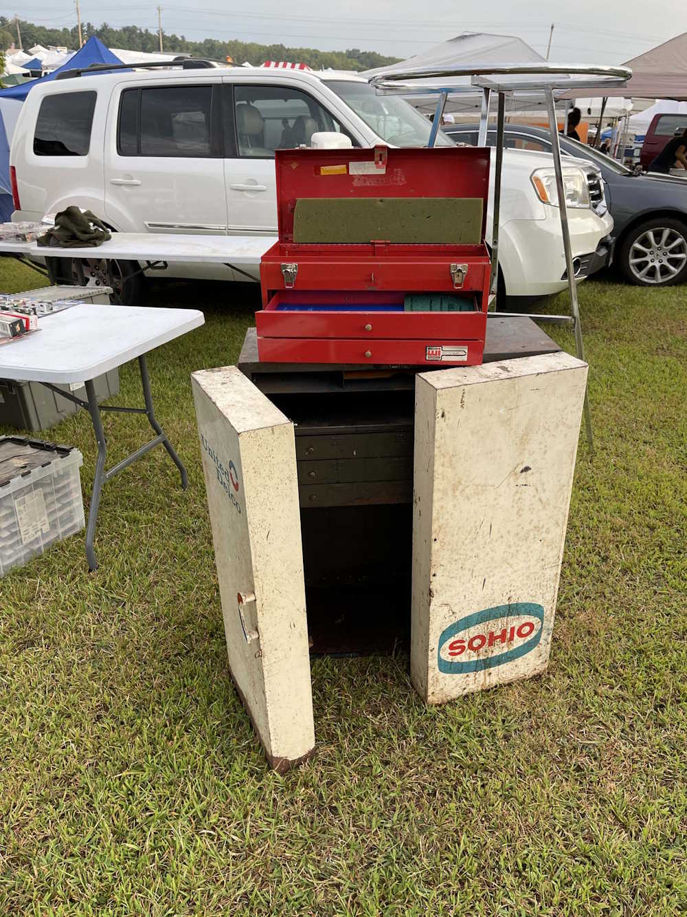
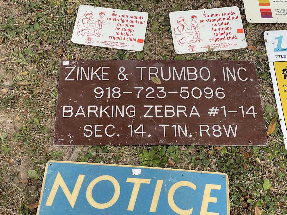
Standard of Ohio vanished in 1984 when purchased by BP.
A couple of old phones. The spotlight in the box beside them went home with me.
A real spinning wheel.
I suspect this was from a mine, but it was amusing regardless. (It’s from an oilfield, from what I’ve seen.)
It looked like it was going to rain about 11AM, so we finished up and headed home.
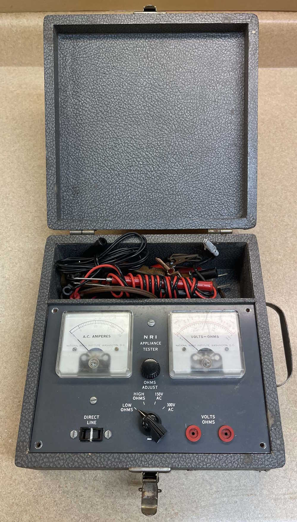
I’m not sure what fascinates me about these little test boxes - maybe it’s the attempt by the manufacturer to put as many functions into a small a space as they can. Regardless, this little test box is one of those devices. Yes, it’s a device that could be replaced by a simple digital multimeter and a couple of cables, but this was supposed to be an all-in-one device with all of the necessary connections to do the job at hand.
This device is a tester from NRI, or National Radio Institute - a former school by mail organization. This device was probably included, unassembled, as part of one of the courses. It’s state gave you a chance to learn assembly and soldering, as well as some circuit basics. It was later marketed on it’s own as the Conar 200, Conar being the consumer imprint of NRI where you could purchase NRI devices without the need for the coursework.
This device came from the 2024 Cuyahoga Falls Hamfest, and was $3. I didn’t really buy it for the test box itself, but more the real copper clips and probes that were in the storage compartment. The device itself was interesting enough (but smells horribly of basement!) that I decided to check it out a little.
At first glance, it appears to be a multimeter - and it is. It features a battery powered two-scale ohmmeter, a two-scale voltmeter, and a single scale ammeter. The volts and amps functions are simple metered measurements without any kind of filtering or scaling save that necessary to make it a high or low range. It has pin jacks for probing the device under test, and a socket so you can do direct amp measurements. That’s all.
It’s a very simple, unisolated device. The cordset is live when the probes are, and vice-versa.
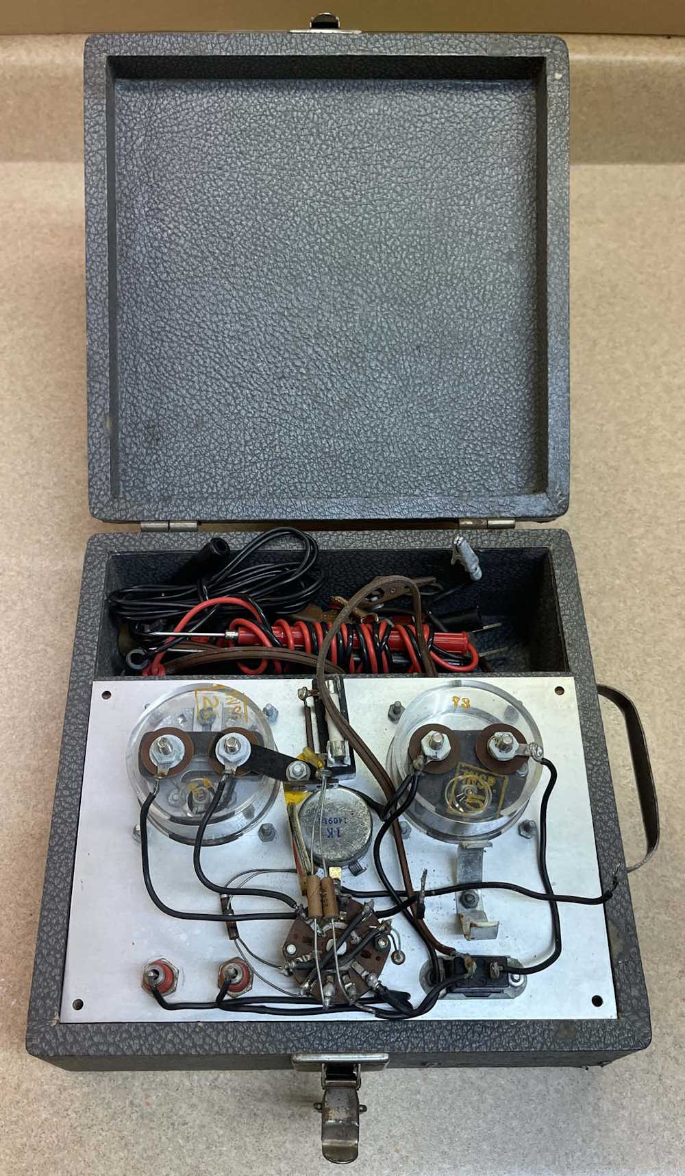
The back of the device is fairly simple as well. A few resistors, a potentiometer, the meter connections, fuse, and some sockets are all you’ll find, along with the battery for the ohms function (removed in this image.) The wire is of fairly small gauge for 20A, so this isn’t something you’d want to run for a long period of time. It’s really about as simple as you can get, and is a pretty good meter for just having around and not worrying about batteries (for the most part.)
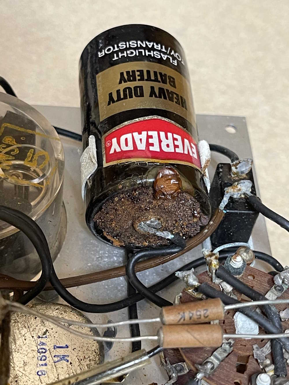
The battery in the device is a little odd, the kit required that you solder it in. There’s no battery holder save the spring clip. You’re absolutely right in thinking that you’re not supposed to solder on batteries, and that’s for multiple reasons. The two biggest reasons is the electrodes aren’t really meant to handle heat like that, and in newer batteries the electrolyte is wet(ter.) Heat could potentially cause it to burst or burn.
The battery in this one had leaked over the years, but fortunately for me it was a carbon cell. The electrolyte caused oxidation on the battery surface, but there’s no alkaline corrosion mess all over the place.
I’ll probably stick a battery in it at some point and see if it works. I can’t believe it doesn’t, there’s nothing there to not work!
I couldn’t get the terrible smell out of this…it went by the wayside.
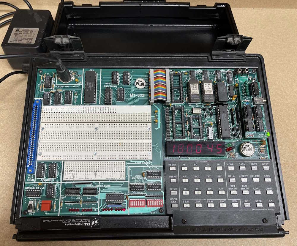
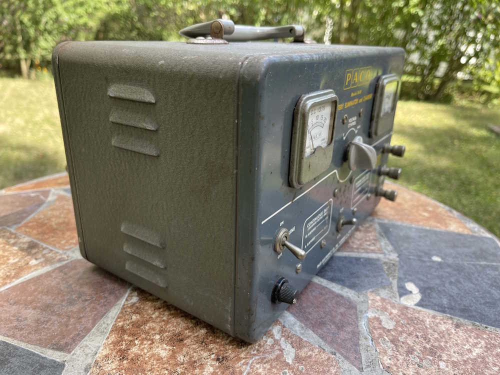
It’s been a while, hasn’t it, old friend? I didn’t think you worked anymore, but it looks like you’re still sitting there patiently waiting for input. Your power connector is loose, so we need to see about that, but I’ll see if I can find your manual and make some magic.
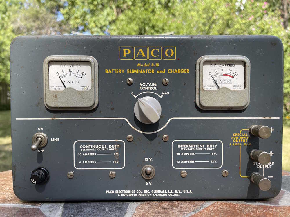
I picked this guy up at the Columbus Hamfest for $5. It claims to be a power supply of sorts, and a battery charger. It is lopsidedly heavy. So at minimum, there’s a nice big transformer in the thing, if all else fails.
It’s fairly unassuming from the outside. The front has the business end of the device - two meters, output terminals, output adjust, and a couple of switches.
As a note, this thing is only 6 and 12 volt, with a little wiggle room.
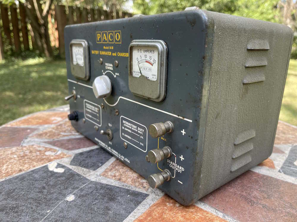
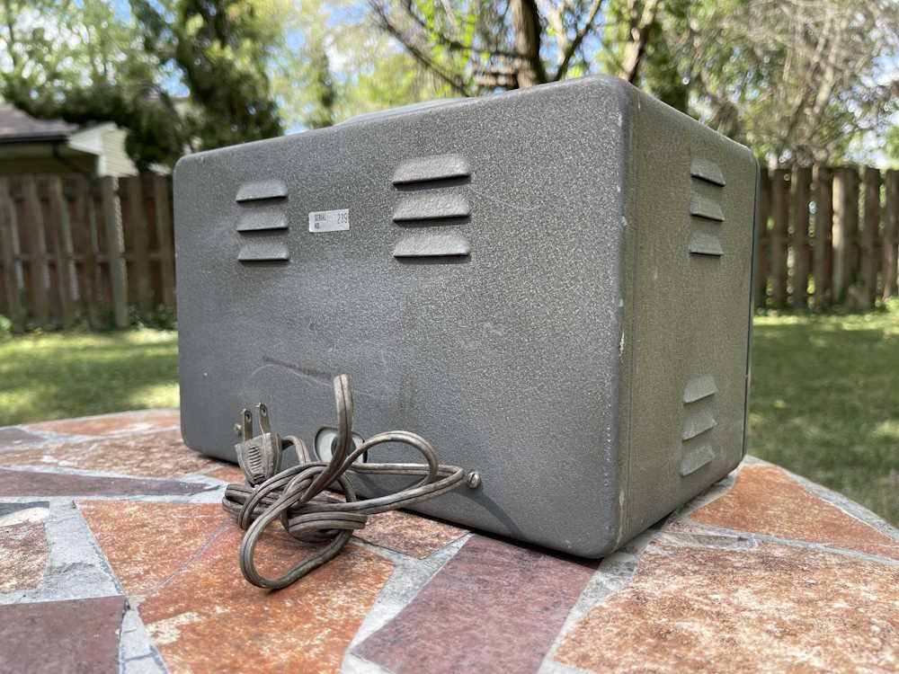
The back and sides are just as unassuming, nothing except some vents, the cord, and a serial number.
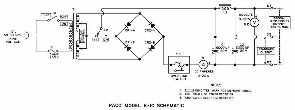
You’d think there’s some sort of regulation in this device, right? Wrong.
There’s pretty much nothing inside of this guy. Apparently, the only regulation is YOU, and that’s by turning the dial on the front of the device!
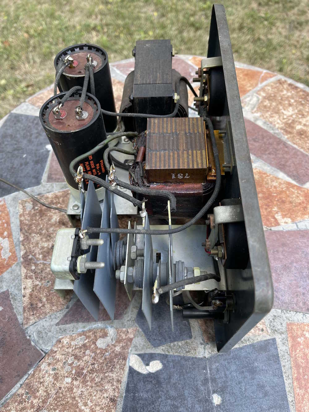
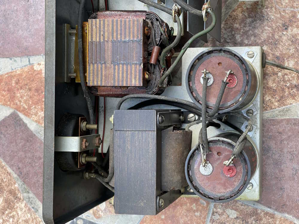
Inside, it’s a history lesson in electronics.
Lots of cloth-coated solid wire and big wads of copper and metal make up this device.
Here’s the power transformer, two giant sized but comparatively small value capacitors, and a giant choke in the middle that hides the voltage adjust tap.
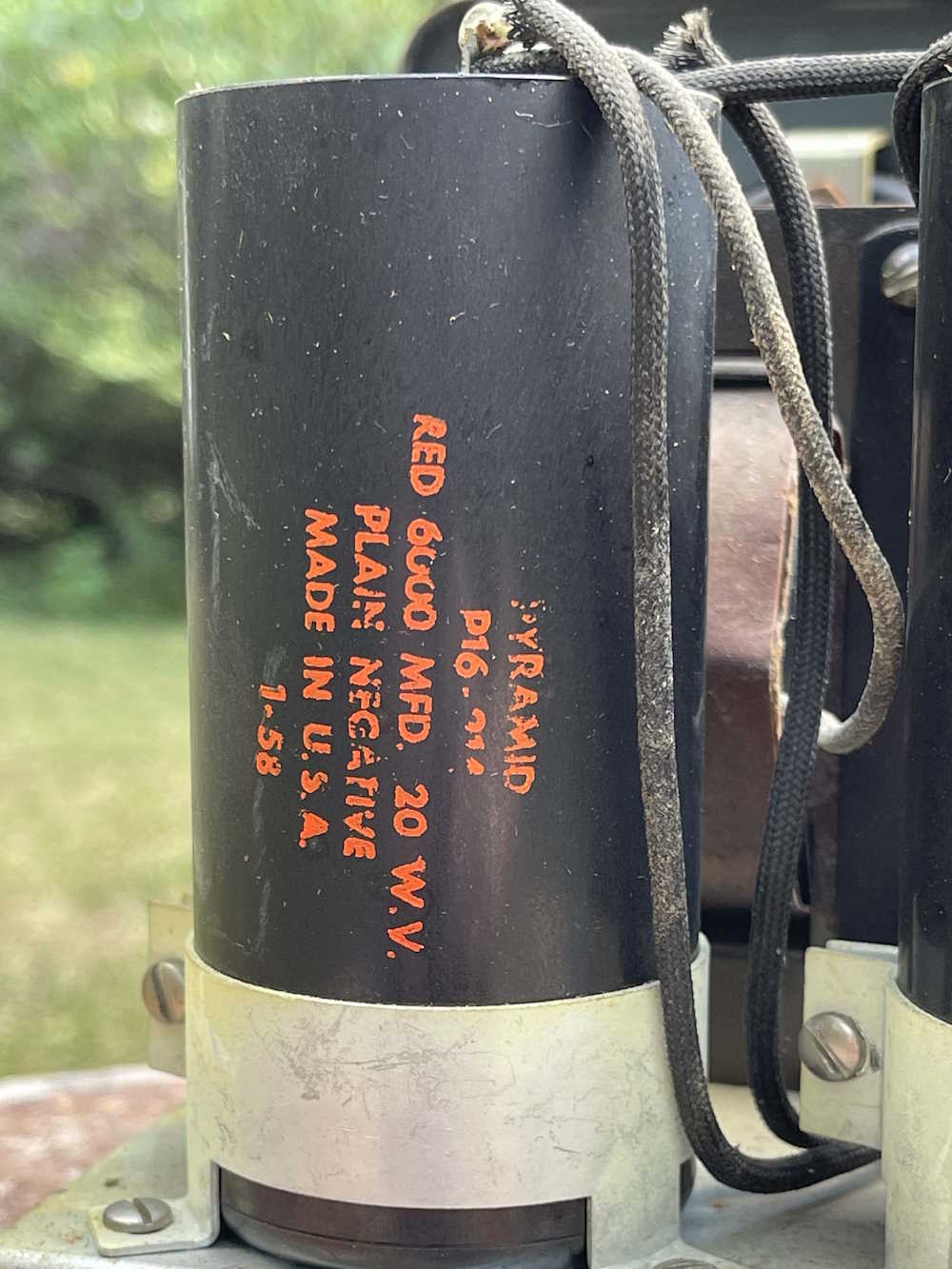
Here’s some boom cans, aka old capacitors. These claim to have been made by Pyramid in 1958. 6000uF at 20V - these can be replaced by 6800@25 for about $4 each, and two of them would fit handily in the space taken by one, with room to spare!
No, I’m not going to try and charge them!
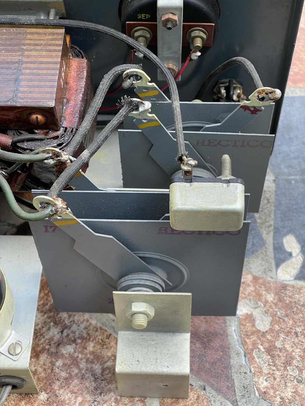
Last, we have the business end of the device. The rectifiers - in this case, giant selenium plates. I wonder what kind of condition these things are in. Are rotten eggs in my future?
This is certainly a product of it’s time - it’s interesting in that it’s a battery charger not made by one of the companies that did such things at the time, but also tries to be a primitive DC supply for device bench testing. Now, of course, we’d just grab a 20A switcher, but this thing was what you had in the 50s.
Is it going to go back in service? Not until I can at least get some new capacitors, but even then - it may just end up as nice power supply transformer in a box. Who knows where this is going…