Saturday was perfect. It was about 80F, partly cloudy, and the grounds had started to dry out enough you could walk and reasonably expect to stay on the surface.
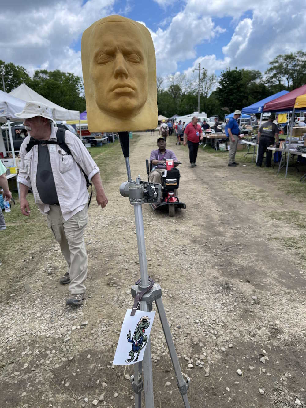
And the weird stuff came out as well…
All the vendors that toughed out the previous day were open displaying all kinds of electronic wonders. A steak tip dinner was had for lunch, and it was awesome as always - much better than the burnt burgers and nasty nachos offered by the other venue. We spent about half the day going through the flea market looking for things to take home.
Here’s what I saw this year on Saturday:
The small National almost went home with me.
A friend checks out a radio.
Some more radios.
Old HP scopes.
Consumer radios playing now that the rain had passed.
An old school transistor tester.
Some tombstones being displayed. All played.
This oddball frequency counter came home with me.
Some nicer examples of prosumer radios.
This DJ player almost went home with a friend.
Want to customize like it's 1999?
All it was missing was the mag wheels option (017).
Various equipment.
More equipment. The scope had no trace.
Even more stuff.
If you remember these, don't.
A couple of nice examples.
If I didn't have a scope I'd have bought this.
The little Heathkit radio was interesting.
The old Hickok logo was quite cool.
One of many Hammarlund radios.
IMG_8684.jpg
How we used to print commercial checks.
An interesting GE radio and some commercial gear.
IMG_8687.jpg
A radio and antenna rotator.
Surprise! More radios!
K E K - Ahead of their time?
A console that was in pretty decent cosmetic shape.
Just stuff in the back of a van.
I bet you'd never guess…it's radios!
Those old Kraft joysticks…
This guy always has some cool odds n ends.
A homebrew rig.
Old school SpecAn.
A lot of Motorola gear this year.
A cool programmer device.
I bought some strawberry waffles here.
Fabric belts for radios in the original case.
Some table radios.
Mechanical reverb!
A radio that's art and science.
A lot of military gear.
Attenuation.
An AC meter with multiple ranges.
A small shelf of random things.
You know what these are by now.
An assorted lot of things.
A bunch of different equipment.
Where did you put the network analyzer, comrade?
It was keeping the table down.
I don't know, it's just a neat piece.
An endless sea of test equipment.
PEW PEW PEW
I feel like someone robbed a fallout vault.
Giant filters.
A collection of old radios. Is tape really needed here?
Millie Amp strips to make ends meet…
These are cool looking but not terribly useful nowdays.
Another homebrew rig.
An archival tape deck.
Bandmasters.
Old tape decks.
More old tape decks.
There were a lot of Bandmaster radios this year.
Hey look, more radios!
Some big stuff.
I'm surprised they weren't sinking into the ground.
Old gear from the military, then a radio club.
The last of the WJ stuff is finally showing up
Radios and parts.
Audio gear was common this year, as always.
When you need to wake the dead.
When we had to adjust the points on cars.
Some sort of military VHF device.
Solar cells.
Some sort of Chinese HF gear.
This is interesting because of the Crosley tag.
Every WWII movie needs one of these.
More gear.
A cool barometer.
Do I need to explain?
A lot of these little Heath transceivers this year.
If you're getting 500 rads per hour, you're not reading this meter anymore.
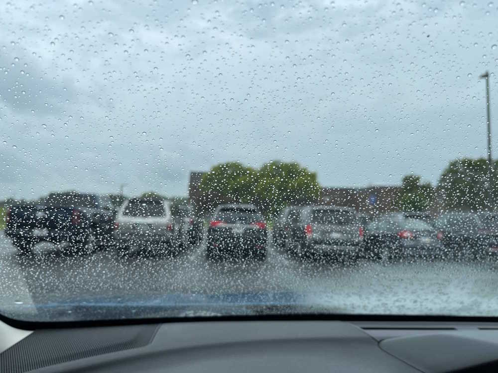
Friday promised to be a rainy day, and it wasn’t a lie. The RADAR showed rain, and lots of it!
And it was wet…
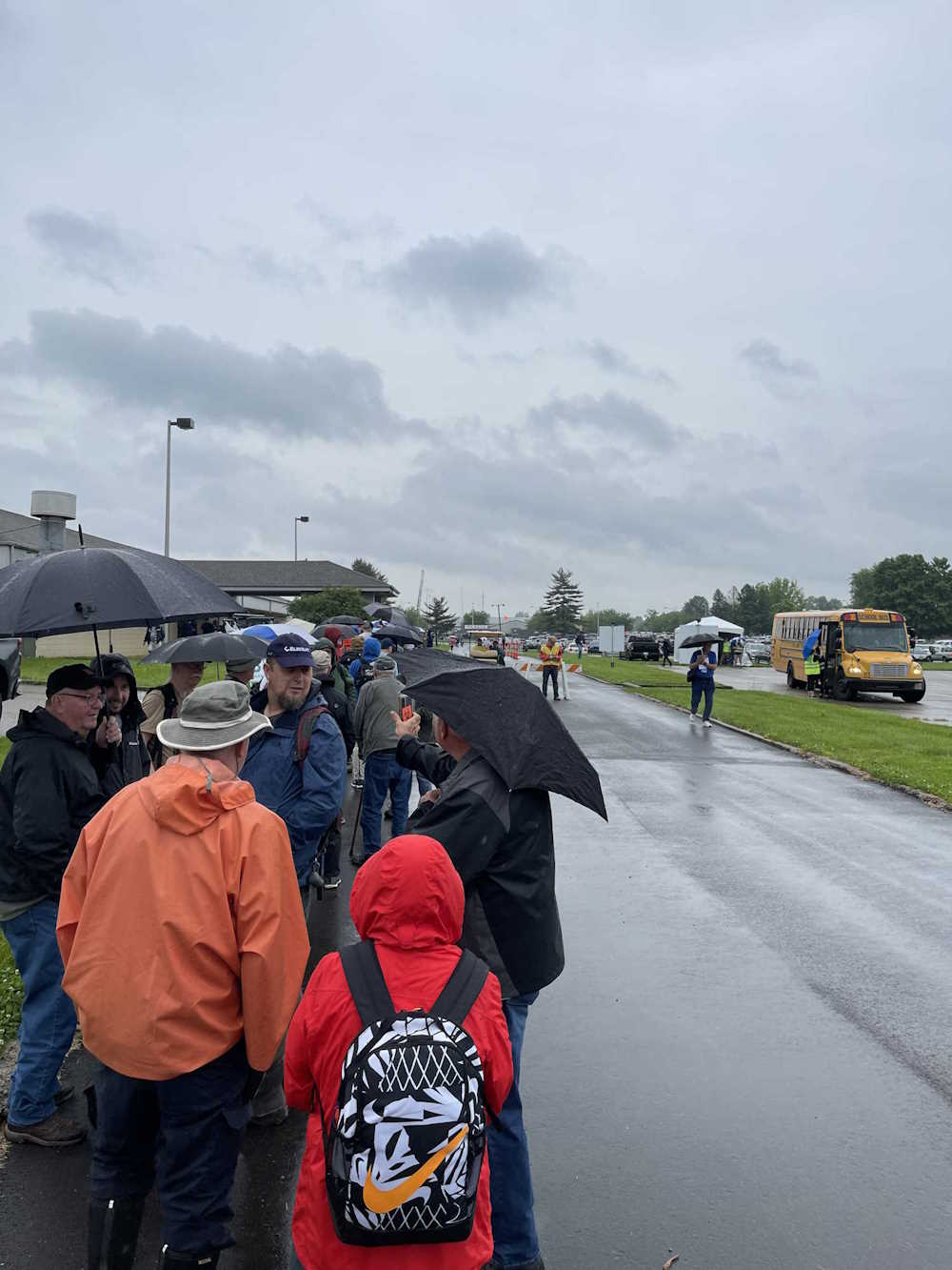
The line ride was soaked.
But that didn’t stop me from playing in the mud like a happy little wereboar. There were still plenty of vendors open with tents over their wares, and I still brought home way too much. I spent about 4 hours wandering the wet ways, and of course it decided to stop the minute I was finished! I was soaked by then, and ready to go, but Saturday and Sunday awaited.
Here’s what I saw this year on Friday:
The requisite radios and a cool tape deck.
A stack of classic Apple and Tandy.
Lots of test equipment shows up at the show.
As does lots of random parts.
Clubs set up selling things.
Random items for sale.
Expensive equipment. Is there a rain discount?
Simpson made these meters for Heath.
Radios and amps everywhere…
All kind of gear for sale.
A lot of these showed up this year.
Trying to keep the water off.
The little Tek scope was cool.
It's a high power something.
A silent key sale. I took the generator.
Lots of Heath gear this year.
Conar was a nameplate from NRI.
It probably doesn't care that it's wet.
Some things are sold out of the back of a truck.
Test equipment…ONLY!
A lot of things were covered up.
The gods smiled, and the S38C went home with me.
Just stuff.
Just like Emergency!
Things for your fallout shelter.
These boatanchors kept the ground from flying away.
Sunday was much like Saturday, except warmer. 85F and no rain, the infield was dry, and crowds were low - of course, many vendors pack up the night before. All the food vendors were still there, so I hit the Bourbon Chicken stand and took home a bottle of sauce after eating my delicious chicken.
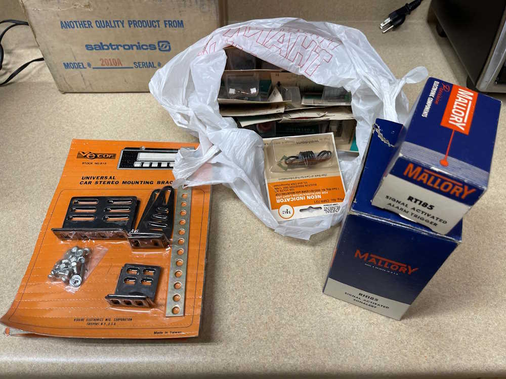
There’s a vendor that always has tables of stuff for a dollar. I always spend a few dollars here, this year I brought home a bag of indicator lamps of differing styles, some packs of mounting brackets, and a couple of oddball alerting devices. The bag also contains some pin jacks from another vendor that were 2 for a quarter, so I grabbed a handful.
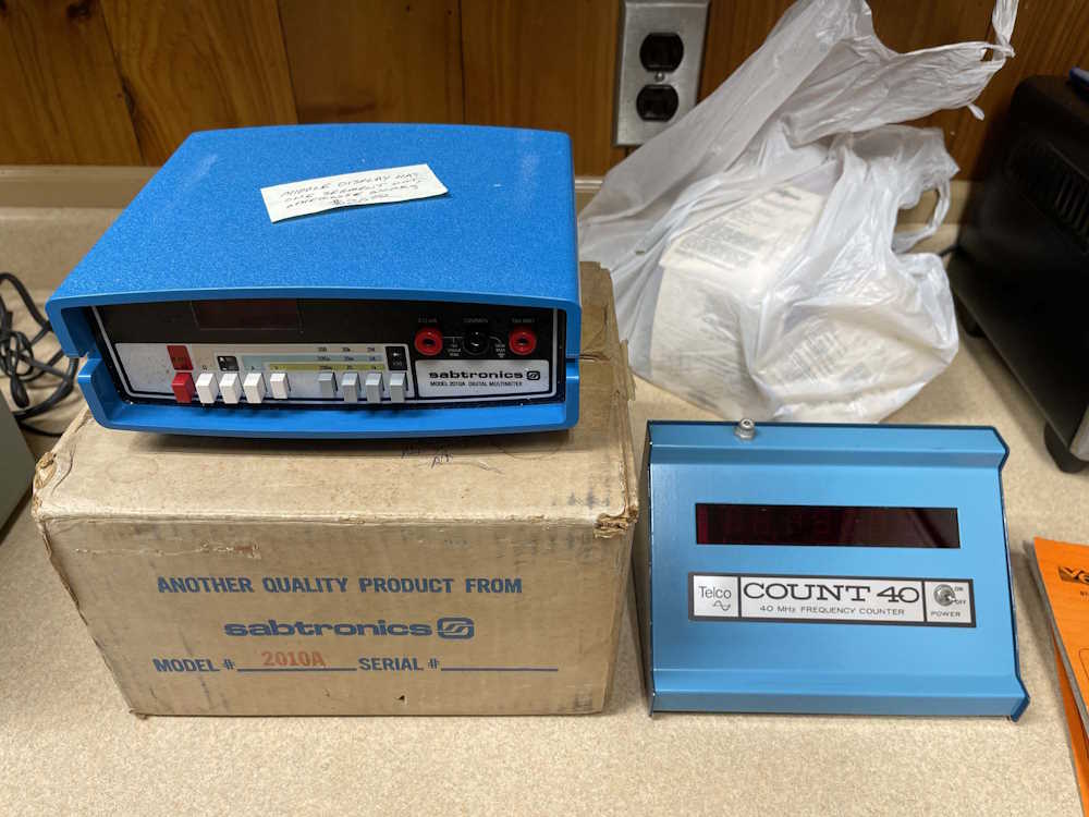
I can’t not buy a voltmeter, so this Sabtronics unit compliments the counter I got Friday. The seller claims it works with a bad segment, that will just be a display replacement. The cool thing about this is it has all documentation, including the shipping box, invoices, and correspondence between the buyer and seller. It cost $2.21 to ship from Texas to Missouri in 1979!
The counter is just…a counter. It’s in an odd case. It’s from the 1970s. I have no idea if it works. That’s for another day.
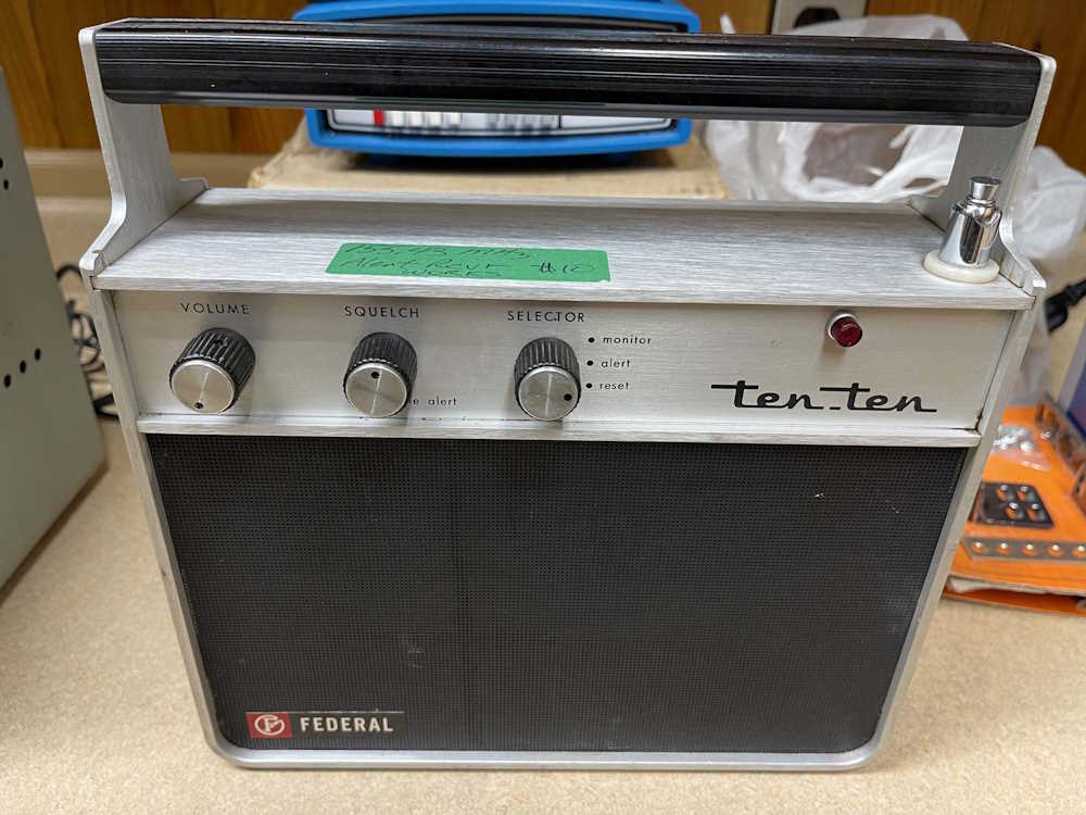
Last is this odd radio. It’s a Ten Ten brand, manufacturing by Federal Signal. It monitors one frequency. Just one. I’m hoping I can convert it to work on the weatherband, which may be as simple and changing a crystal. We’ll see.
That wraps up the 2024 Dayton Hamvention. General pictures of the event coming soon, I took quite a few this year!
Saturday was a good day at the Hamvention. It was warm, things were drying out, and everything was open. A few vendors appeared to have left, but there’s always some that only attend Friday, expecting it to be the big day.
The mix of products has changed over the years. Gone are the big stacks of old test equipment, piles of old radios and televisions, and the endless sea of Watkins-Johnson equipment. CBs have faded as well from their peak a few years ago, and computer equipment is all but gone save for a few “classic” machines and newer hard drives that got replaced in the never-ending “moar stoarage!” quest. Hobby gear from the 60s seems to be common right now, with big radio gear still being common but lessening.
I picked up a few things Saturday:
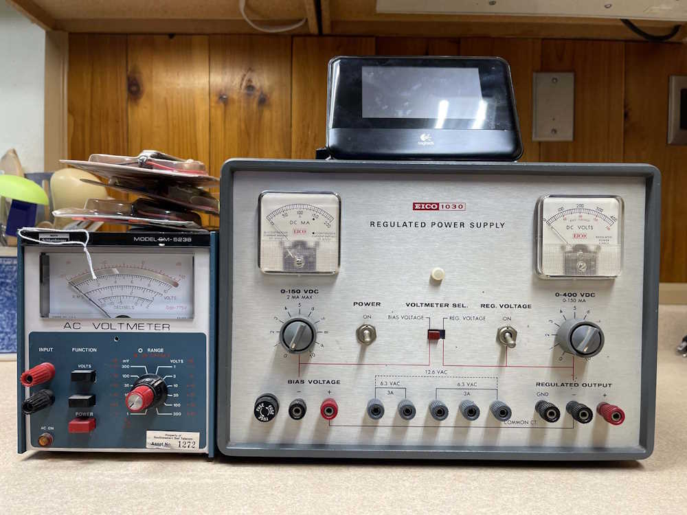
I picked up this Eico power supply. It’s designed for tube work, providing 400VDC and 150VDC for plate and biasing. There was a second one, not working, and I was going to offer on both but the dead one sold first. Probably for the same thing I was going to use it for - parts.
The little Heathkit meter is AC only, but the meter goes to the middle when it’s turned on. Something leaky or shot, most likely. It was last calibrated in 1995, was used by Southwestern Bell, and the cal house was in Dayton. Kind of a cool thing.
A manual for both items is in order before use.
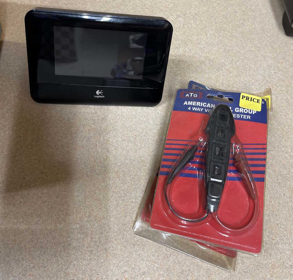
This Squeezebox Touch was in a box of random devices. Logitech used to have this awesome music player system that you ran on a server at your house, and you could connect multiple music players to it that played streams or your local library. They discontinued it because I guess you can’t sell ads in a service you run yourself. Regardless, the players still work fine and this clean example of one of the touchscreen models was cheap. I need to try it out, if it’s dead then oh well.
The other items are AC line testers. Unlike most, these have 120, 220, 380, and 440 lamps. At a buck each, I bought 3 and will toss them in the toolbag.
That’s all for Saturday, I was planning to (and did) go back on Sunday. I picked up a few more items to take home because vendors were willing to deal so they didn’t take it home. Stay tuned!
This year’s show started out rainy, and it rained until I was done browsing the flea market about 4 hours after open. Of course!
Really, the only thing I wanted out of the show this year was to find a Hallicrafters S38C. I had one of these years ago, and gave it to a family member. They swear they gave it back, but I don’t have it and I don’t remember giving it away. Not a big deal, it was a pretty poor example of the type but it did have a manual with it. I ended up coming home with a frequency counter - I need one to fix my other one that suddenly stopped counting, and got a good deal on a boat anchor of a signal generator. I also found what I came to the show for - an S38C.
The Frequency counter is nothing special, just a counter. It works. I saw it working at the show, so no problems.
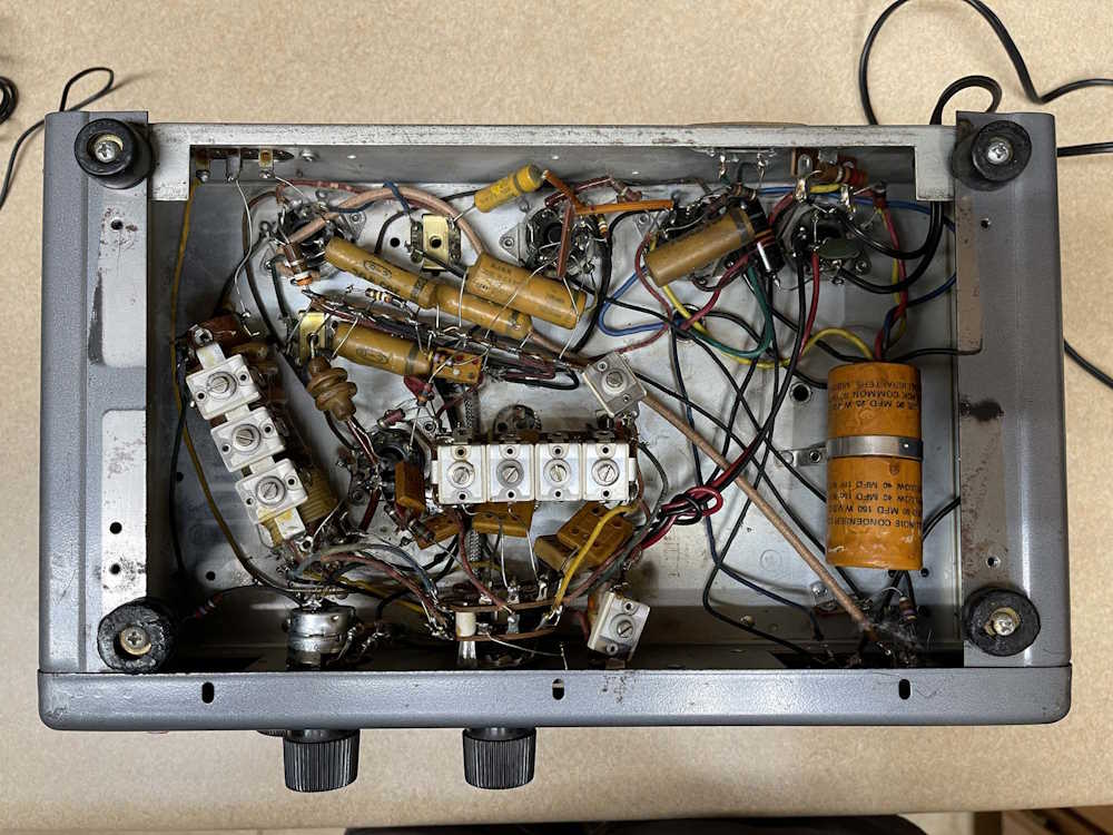
The gods smiled on me because this S38C was sitting at a booth with a couple of other similar radios that an older gentleman was selling because he just didn’t have the time or interest anymore. It’s in great shape for the age. It’s missing the back, of course, and a knob was kind of busted. Not a big deal, the case and innards are in excellent condition.
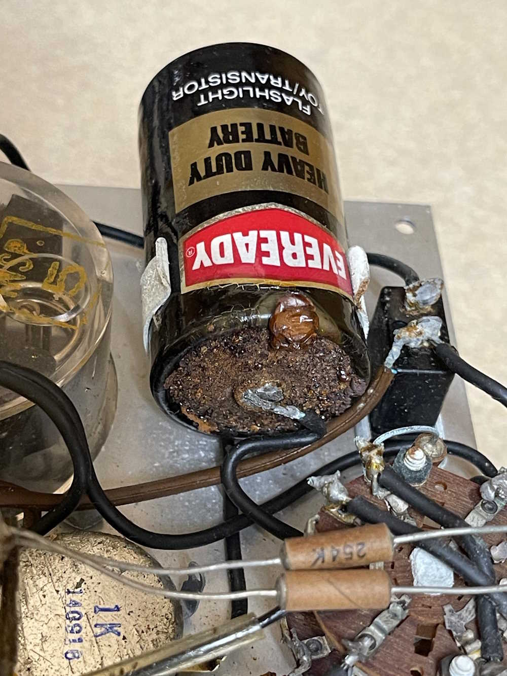
Everything inside is completely untouched. Bask in the glory of leaky wax paper capacitors and bumblebombs.
The filters are bad, of course. That’s expected, and the 150V capacitors won’t be too hard to acquire. If I can find some at the show tomorrow that aren’t super goodly chinesium, I’ll get them - otherwise, a Mouser order is in my future.
future me note: it has bad IF transformers.
The last item is the signal generator. It’s in ok shape for the age. What caught my eye is the beautiful flywheel tuning dial. Just a pleasure to spin and turn. It works, but has some issues - the signal kind of fades in and out. No tsure what’s going on here, I’ll open it later and take a look. However, when it does work the signal is quite nice.
future me note: it wasn’t worth repairing.
That’s it. There’s one piece I told myself if it’s there I’ll get it tomorrow, so we’ll see.
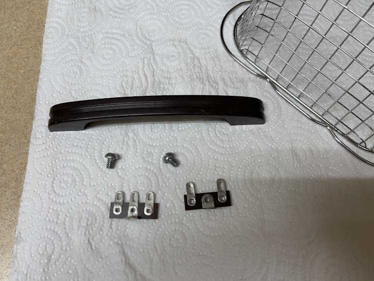
Not much this time, just some prep work for the big stuff.
First was to unsolder and remove the RF jack on the front and find something to put in the hole. This piece of plastic from…who knows…almost fit and will be secured with some RTV later in the project.
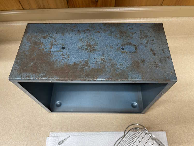
You’d never know, but the case was washed.
The handle and some hardware was given an ultrasonic bath to clean it.
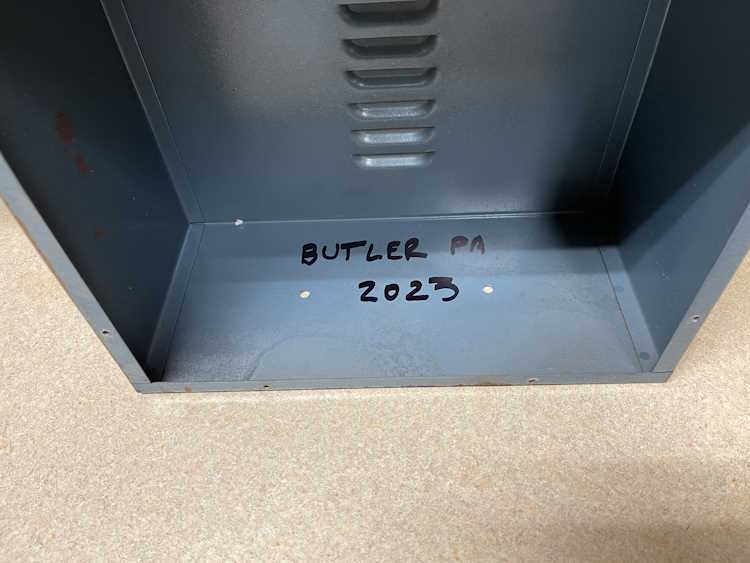
The location and year of purchase was noted inside.
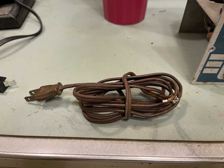
And the old, almost hard as a rock cord was removed.
Next is to start removing components. I haven’t decided if I want to do it all at once, or try to do it a part at a time. I can certainly get cleaner results removing everything and doing it all at once. I have the assembly manual, so - probably all at once. Stay tuned!
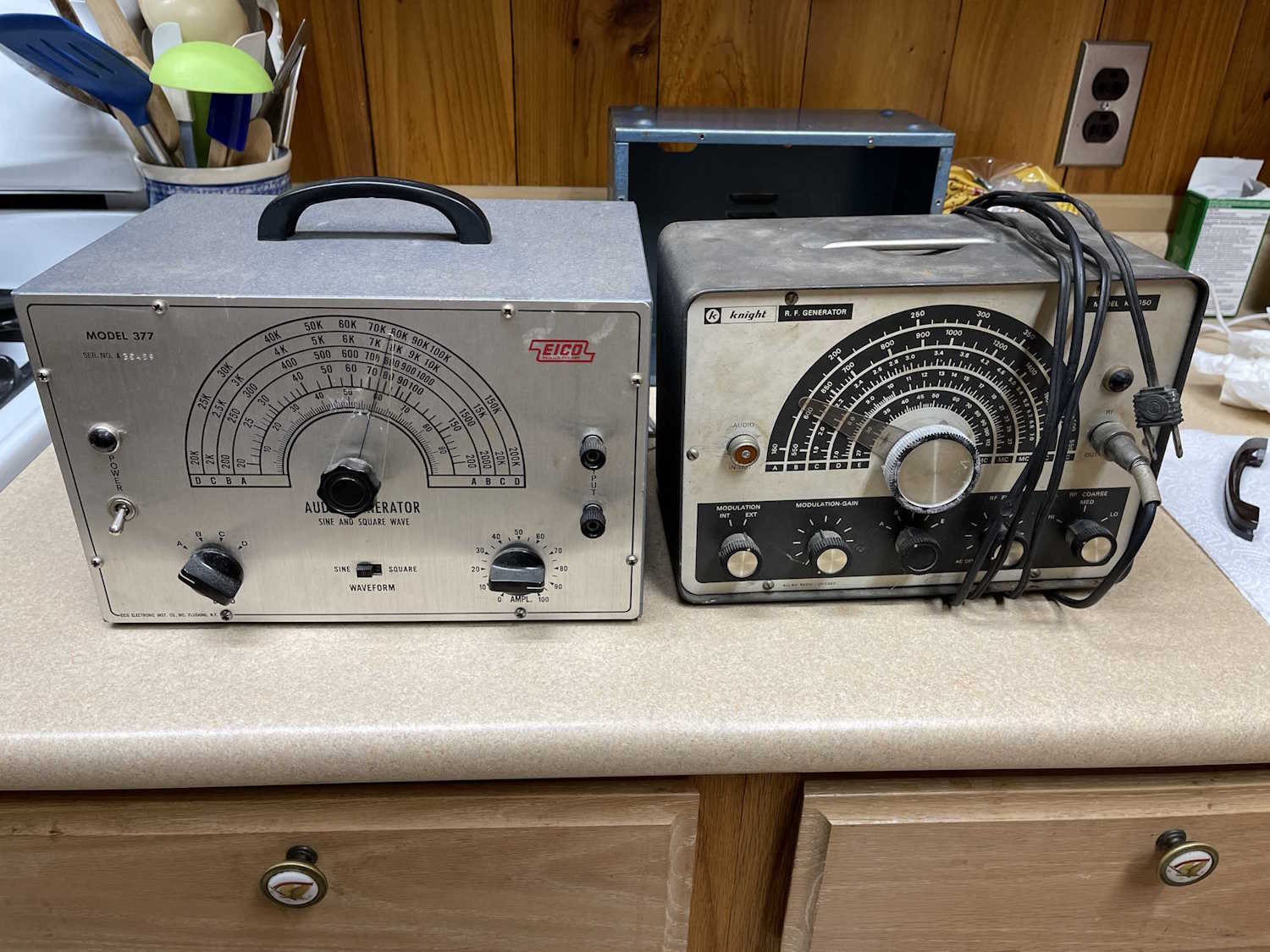
I really didn’t go to this show expecting to buy much, and I didn’t - I spent $30 and brought home these two items:
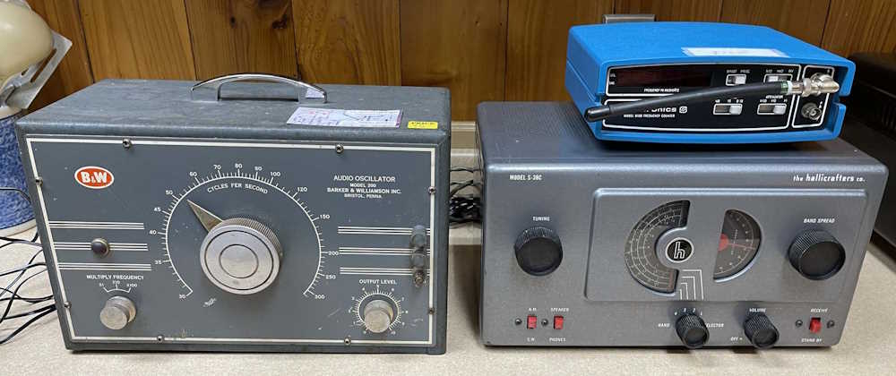
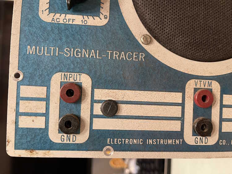
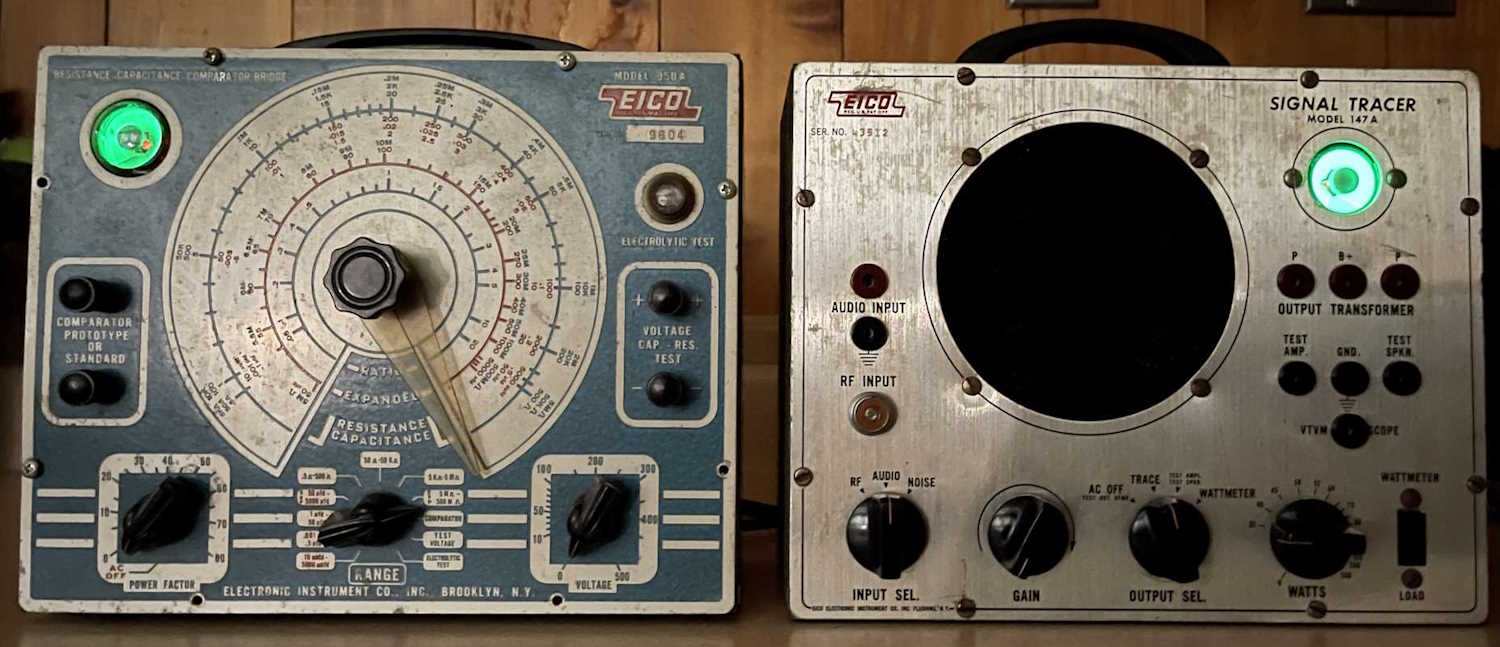
The audio generator on the left works, but has a messy sinewave output. I’m not sure if this is normal, but knowing some of the other equipment I’ve had from this era - it may be. There are some capacitors in the unit with high ESR, so I may play with it a bit before making further judgement.
The RF generator on the right has an absolutely miserable output, the entire bottom half of the output waveform is clipped off - which I thought was bad. Nope, they apparently overdrove the final amp to the point where that’s the way it worked. It also is overmodulated with internal audio, so this thing was a turd when it was new. I found some suggested fixes, so I may play with it a bit when time allows.
The RF generator was a “Offer I can’t refuse” thing - the guy said take it for $5? Ok, sure!
That’s all - I did want the capacitor checker in my show post, but I restrained myself and someone else picked it up for the low price of $40. Thank you rando for saving me!
I did it again. Too much stuff, but I’m going to blame some of the sellers for being so congenial about negotiating on prices! (Yah right!)
So, what did I bring home this year?
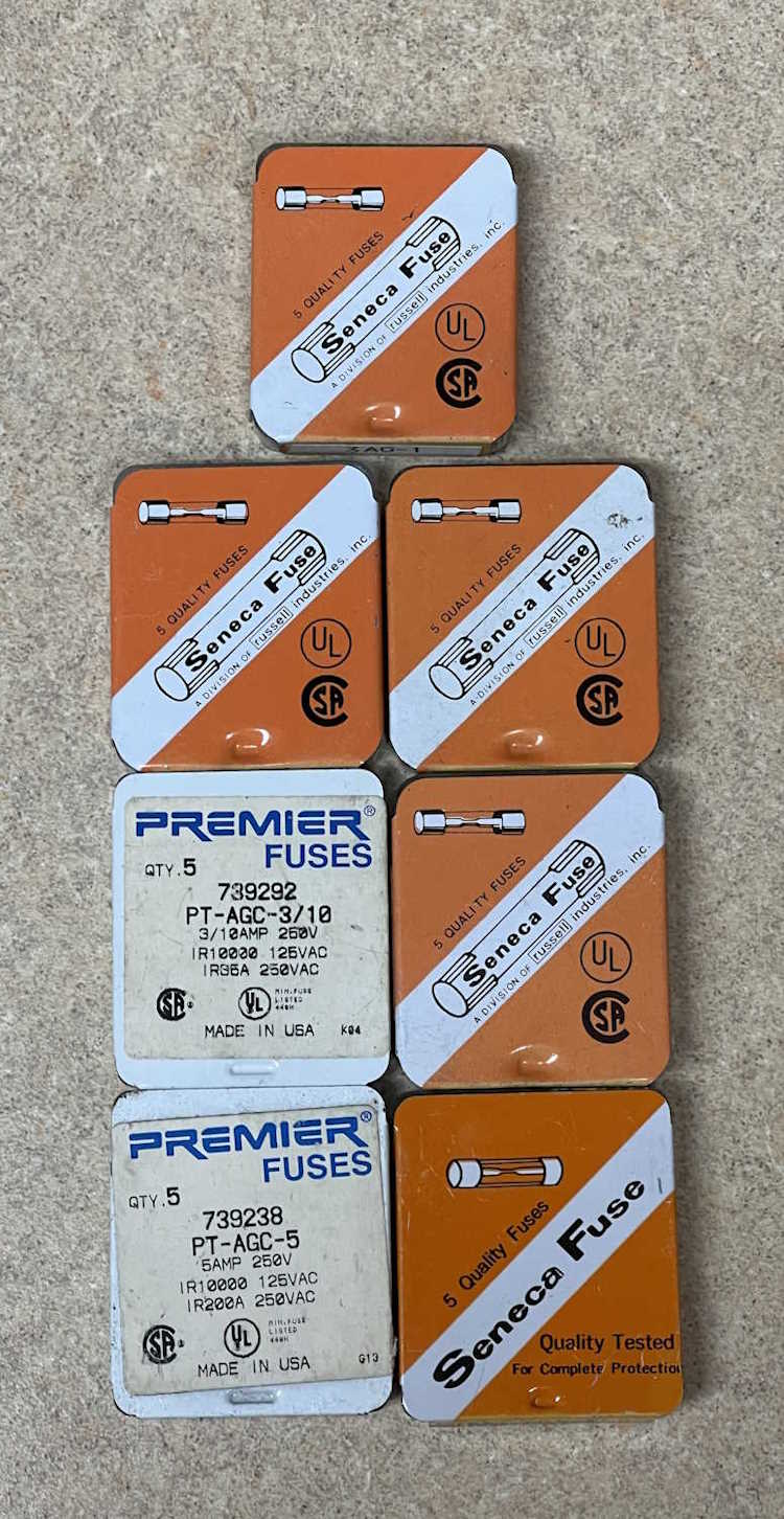
Fuses.
This vendor had a lot of different values, including a lot of fractionals that will cost you a small fortune if you buy them new, so I picked up some 1/3, 1/4, 15mA, and 1A varieties. What’s kind of cool about these things is Seneca Fuse used to be a Columbus, OH corporation, and one of the boxes is marked as such. The company was purchased by an entity called Russell Enterprises, which appears to have long since gone out of business.
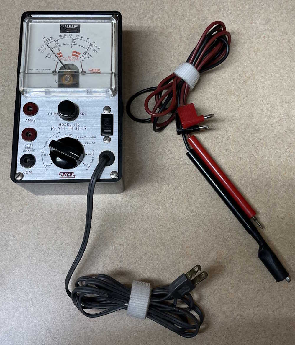
This is a cool little device that didn’t cost much. It’s a primitive hypot-type device that can test for leakage in a circuit. While primarily designed for appliances and other large current consuming things of yesterday, it still works great as a bench voltage monitor. It also performs it’s other functions without issue, so it was a good find - and it had the manual with it. I’m not sure what the leads were for, this device used EICO’s pin plugs. No worries, another set of leads on the bench is always a good thing!
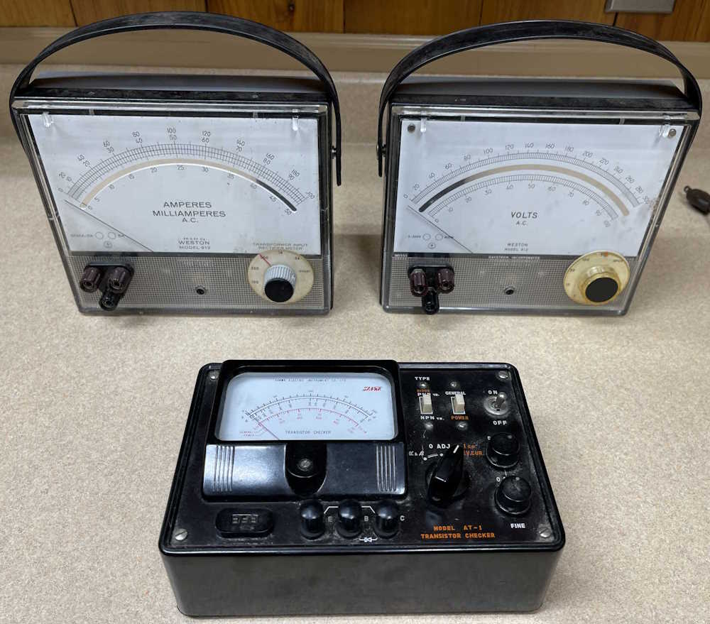
I actually only wanted the AC Voltmeter in this lot, but the seller was really good on the price for all three, so I came home with the AC Voltmeter, a current meter, and the oddball Sanwa transistor checker. The meters are nice dampened movements and work well, but I haven’t installed batteries in the tester to see if it works. Not sure I will, those little handheld device checkers do an excellent job of sorting parts and identifying things for you.
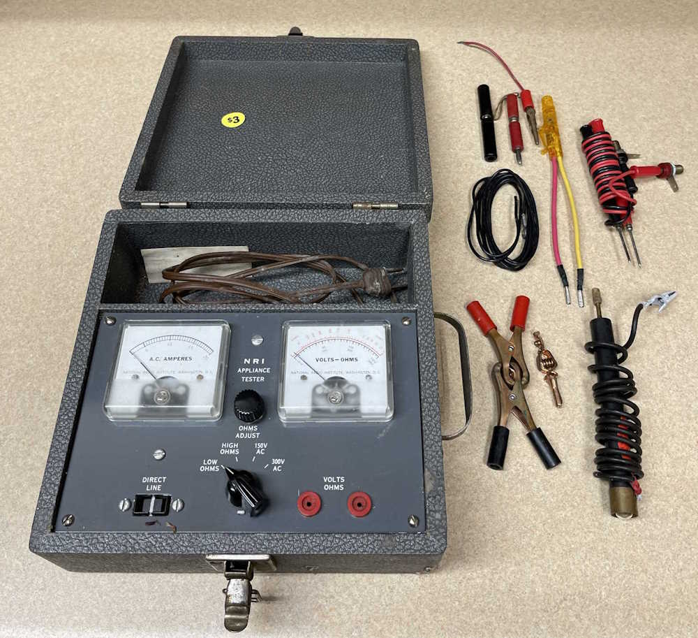
This little meter in a case was probably part of some course offered by NRI Schools, an early “distance learning” company. (Started in 1914 as National Radio Schools, ended in 1999 as NRI - changing tides on the electronics landscape did them in.) While it’s not really of much use, the real Mueller copper clips and other test leads were well worth the price of $3. The device itself sat in a basement for some time, and it smells like it - if I can get the smell to fade, perhaps I’ll find a use for it.
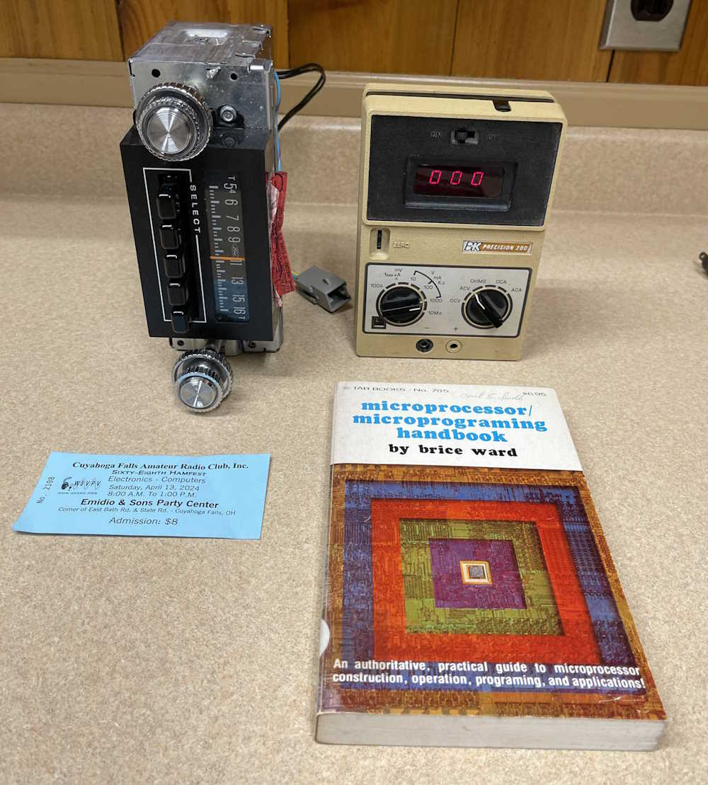
Here’s the odds ‘n ends portion of the program. An apparently new Ford AM radio that I got for a put-in-the-rack project, a B&K Precision LED voltmeter that matches my capacitor checker, and a surprisingly well written TAB book about early microprocessors. I say “well written” because TAB would publish almost anything. Some books were pretty good, but some were literally nothing more than a guy who wrote a book about taping LEDs to various things and called it “101 electronics projects.”
I don’t need more of these, but they were a good price for functional units, and they’re starting to get outrageously priced. These were checked for operation, and will go into storage as parts donors - or perhaps as resale units once cleaned up and re-capped. Who knows?
In all, it was a good show. I didn’t need to drag home some of that stuff, but I did. I’ll see you at the next show this weekend!
It’s not really important to operation, but having clean knobs and lenses on indicators is always nice. Since I have an ultrasonic bath, I’m going to use it.
The knobs on this guy are pretty cruddy, and the power indicator has a spritz of bronze paint across it.
While I’m removing the knobs from the volume and function selector, they get a shot of deoxit to clean and lube them.
Everything goes in the bath for 20 minutes.
In the end, they all come out nice and clean and ready to re-install!
Parts have been ordered, we’ll go through those next.


.")