(It’s actually a TE-189 device…how did I miss that. Really wearing my stupid hat on this one!)
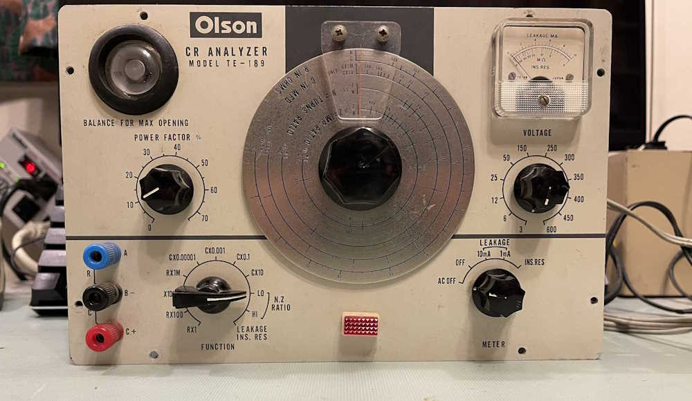
Olson was a Radio Shack type company from Akron, Ohio. Much like Radio Shack, Lafayette, and Allied/Knight, they sold electronics components, kits, geegaws, stereo equipment, and other related items. Changing fortunes finally did them in during the 1980s, leaving only the name Olson adorning much equipment, as well as some research facilities in Akron.
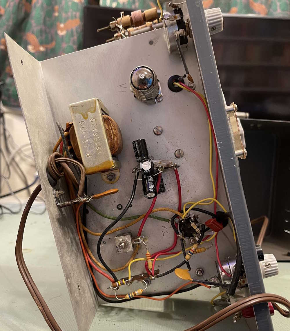
This particular piece is one of many similar devices from the 1960s, being that of a capacitor leakage tester. This one also does resistors, which is of limited value in an era when VTVMs would have been plentiful, and FET VOMs were just on the horizon. It came to me from the 2024 Findlay hamfest, in about the condition you see it in.
This device is slightly unusual in that it uses a 6E5 tube for the eye and features a meter for leakage. The 6E5 was largely obsolete by the time this device was made, the more common WWII 1629 (still somewhat plentiful today!) being used in other devices of this type. The fact that this came from Japan probably has something to do with it.
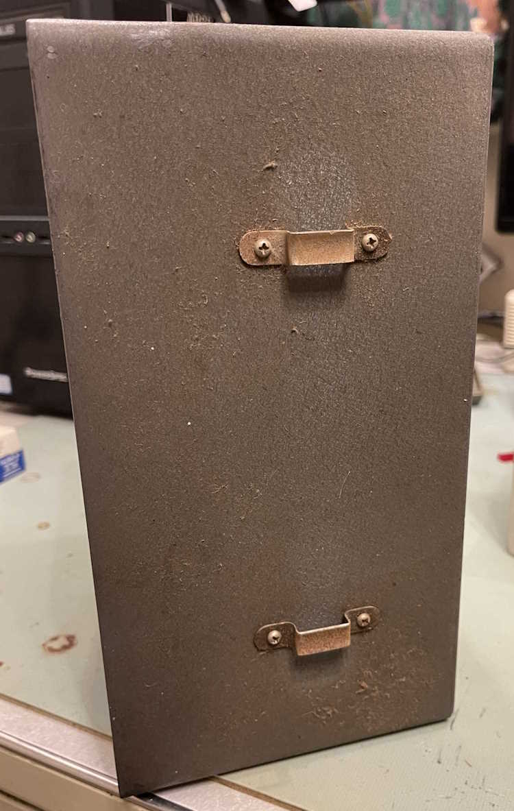
The case for this unit is extremely dirty, and appears to have some sort of oily dirt film on it. It’s almost like this unit was in a shop where shop air was being vented around all the time. This came off (mostly) with a good scrub with some dish soap and 409 cleaner. The handle was broken when the unit was received, being a cheap piece of top-grain leather.
The device does power up, the eye tube is acceptable, but the little neon pilot at the bottom didn’t light. The resistor for this is 50k and the bulb has a domed top, so it’s probably something like an A1C. While this isn’t supposed to be re-lampable, it can be. (Edit: This is relampable. I can’t locate the bulb type, unfortunately.)
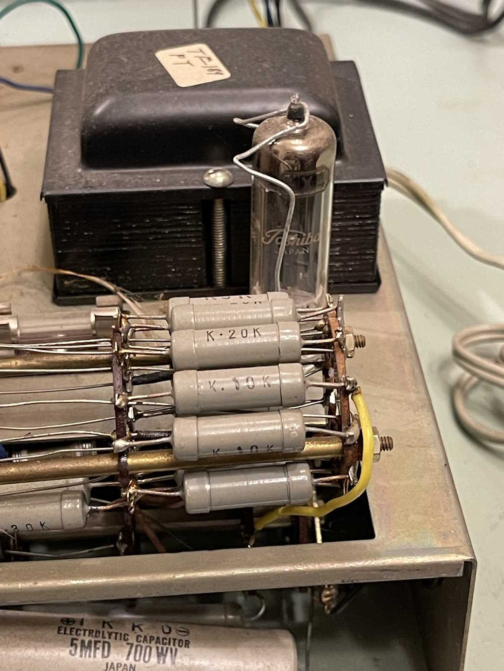
It’s most certainly a Japanese unit, the Toshiba tube and those Mitsubishi-style resistors gives that away in a heartbeat. The big filter at the bottom even says “Japan” on it.
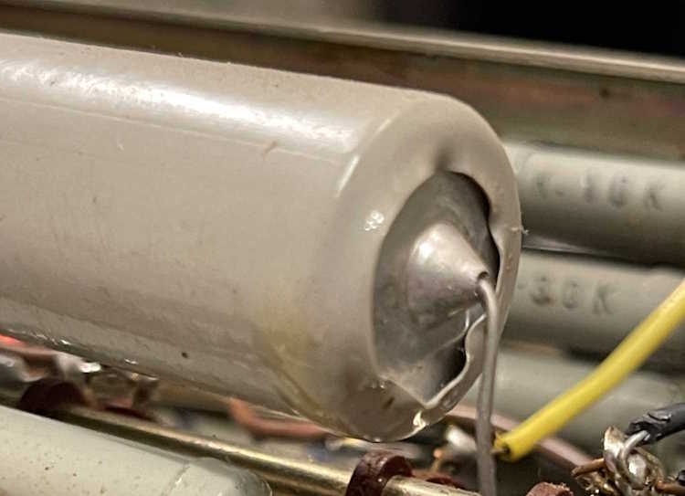
The filter at the bottom is coated with oil. At first, I thought this device was leaking, but further investigation leads me to believe this just collected oil from the air.
There’s not much going on with this device. 1 tube to provide DC and the 6E5 are the only tubes in the unit. There’s no amplification or buffering of any sort.
As this is a fairly interesting unit (to me) I’m thinking about putting it back into service. Some things will need to be cleaned up, of course - those old capacitors with high voltage on them will probably need replaced, as will those nasty across-the-line caps on the transformer. A new neon bulb can be fitted in, and a good alcohol washing of the components to get the oil off will need to be done. There’s also a lot of cleanup - I’m assuming this one was not a kit but had many intrusions over the years. Some things, like the resistor matrices on the switches are well soldered, but other thing, like the connections to the eye tube are simply a mess.
I don’t think it will take a whole lot to make it work again.
That includes removing the sewing pins from the inside!
Back in part 5 of my Heathkit IG-72 series, I was getting ready to button things up when the socket for the rectifier tube started arcing. I assumed there as carbon tracking inside the socket and moved on with replacing it.
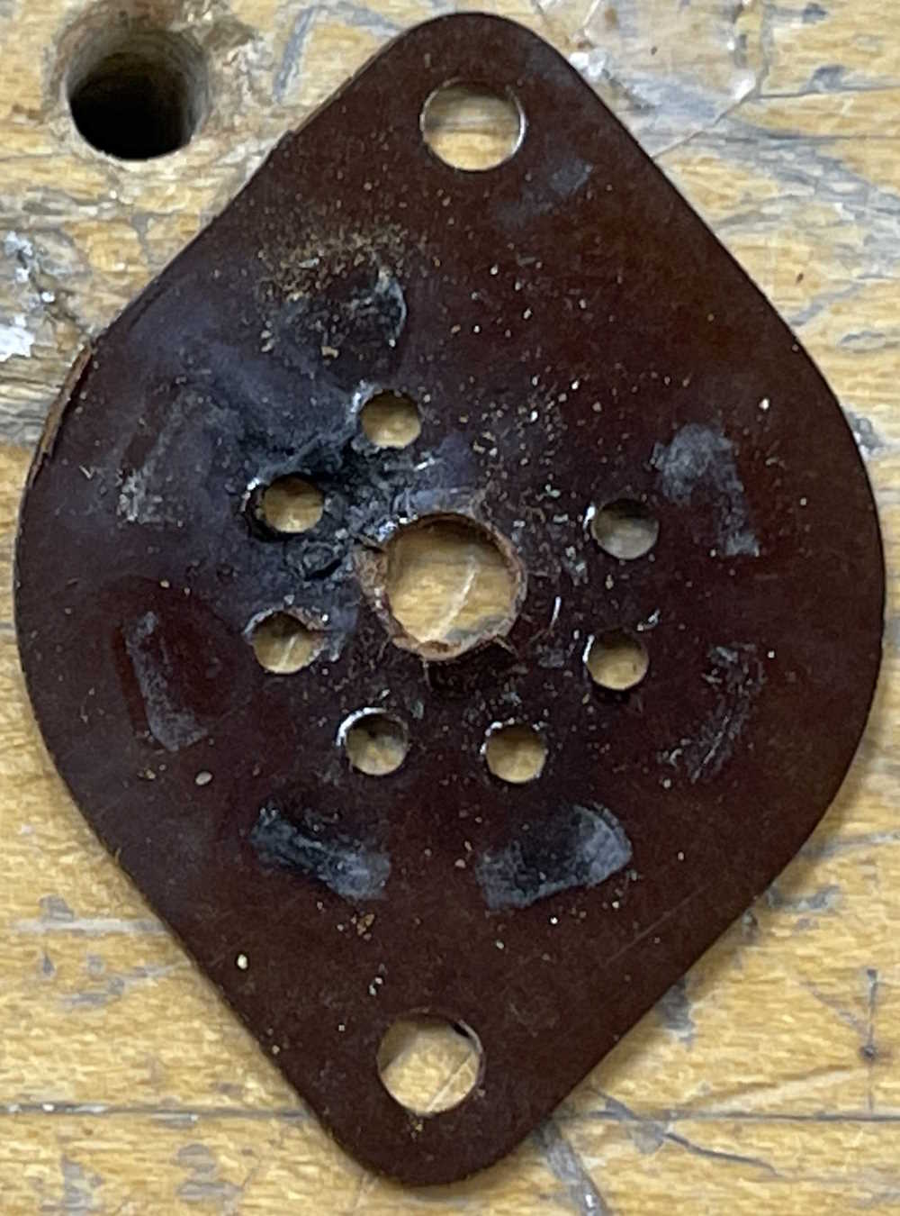
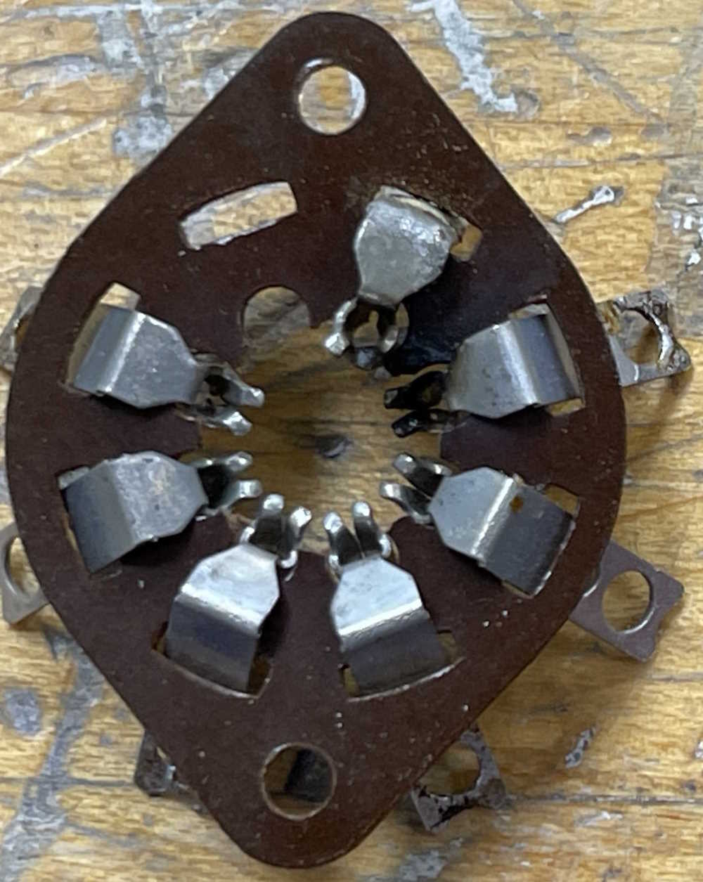
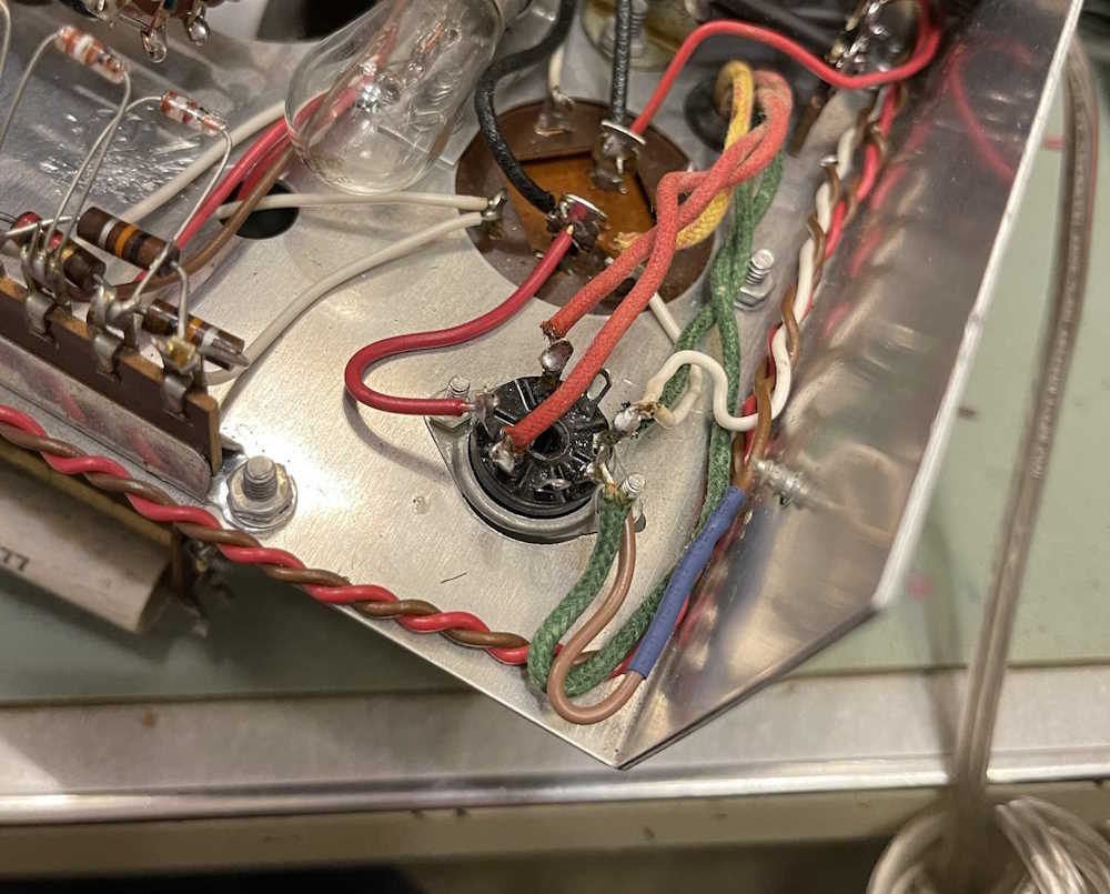
That assumption was correct. Here’s the top wafer:
You can clearly see the arc has eaten away the portion between pins 6 and 7, while depositing a lot of carbon and other debris on the phenolic wafer. The bottom wafer is similar:
It’s not the easiest thing to see, but there’s a lot of soot on the same two pins, and part of the socket crumbled away as the rivet was being drilled out. I’m surprised this thing didn’t arc as soon as it was turned on - but perhaps this is why the device was retired. Who knows, really.
Regardless, there’s a new socket in it’s place that shouldn’t have this issue, and this one goes in the bin - although I may save a few of the better pins for some later purpose.
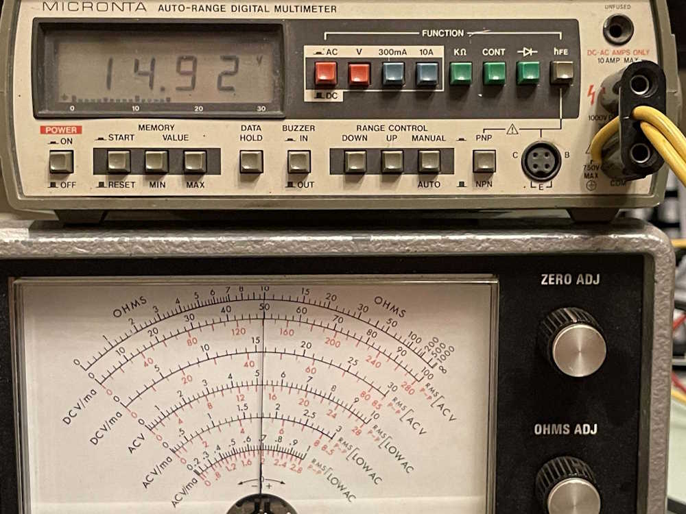
I put the unit back together after replacing the socket. No more arcing, and everything seems to be operational.
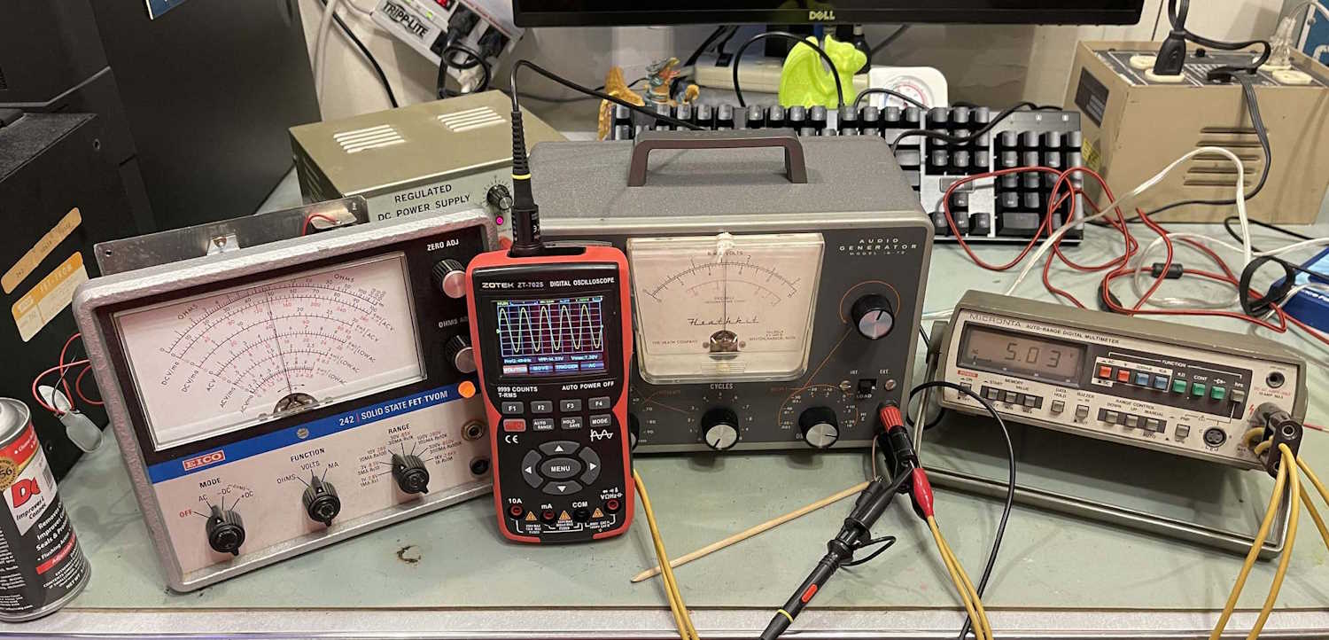
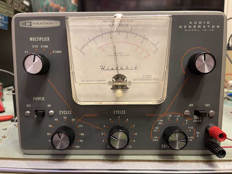
The first thing I did with it is cal the AC portion of another device. The stupid thing is already flat at the bottom, I guess that’s to be expected.
I’ll open it back up and dial it way back to keep the osc in it’s linear range. That doesn’t affect the meter cal at all, since the attenuator and oscillator are separate sections.
That’s it…what I thought was an easy fix was kind of an interesting problem. I’ll have my final thoughts and wrapup when I decide the device is not going to do more crazy stuff on me.
In the last part of this series, I was just getting ready to button up the device when it started arcing across two of the pins on the rectifier tube socket. Carbon tracking is a thing with these older devices, and it’s hard to tell how much flux, solder, dirt, and other grime that this thing has collected over the years, so a tube socket replacement was in order. I measured the centers and ordered some.
Turns out the ones that Heathkit used here are on slightly wider centers than 1”. 1 1/8” maybe? Regardless, I decided to pull the socket out of the one I have as a spare.
I took the bad socket out of the good chassis and noticed something. You’ve probably been screaming this at the screen the whole time, but I apparently chose to stick my head in the mud.
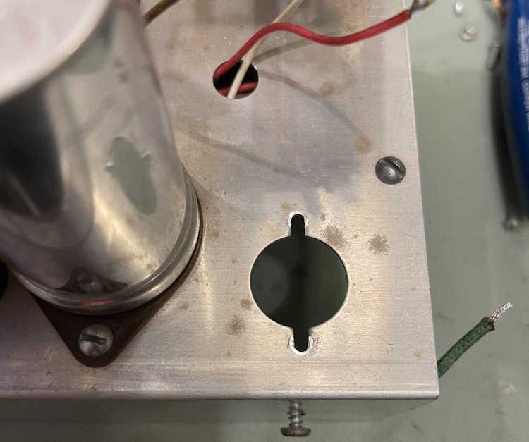
Turns out that, unlike the old chassis, Heathkit slotted the mount holes for sockets on this one. I could have used one of the 7/8” center sockets here. It probably will require some wire extension as the old socket has the pins on a wider diameter, as well as having them splayed out more.
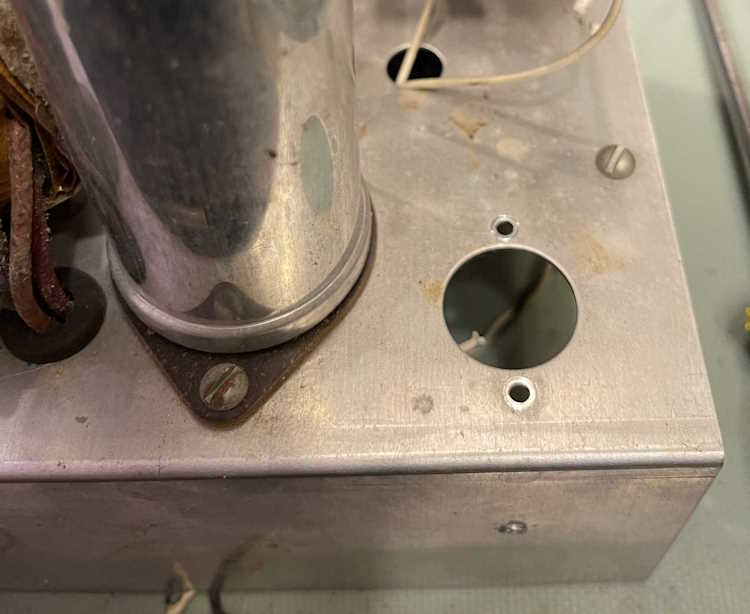
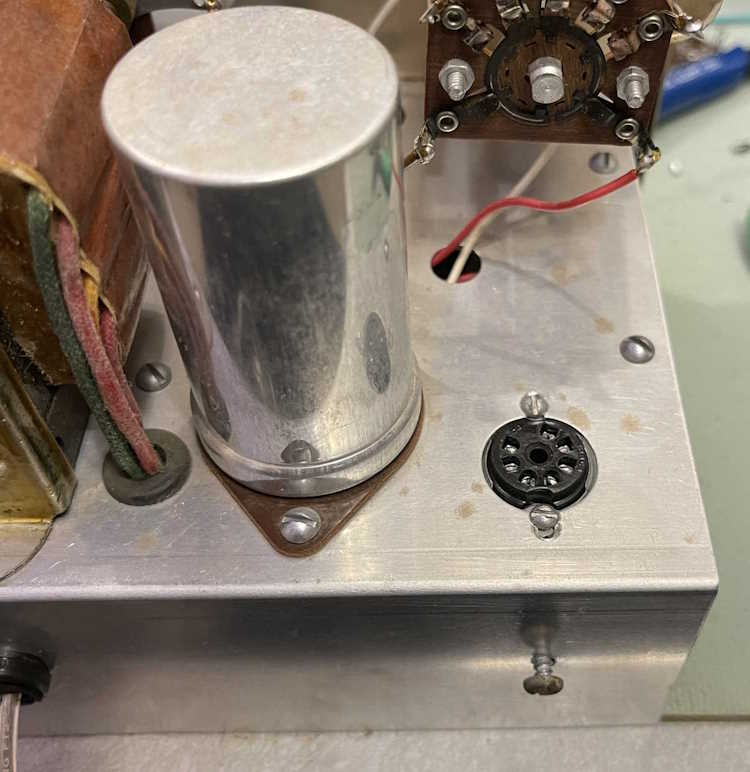
The new socket was installed with minimal issue. It is a little smaller of a hole than it should have, and messing with those small screws was kind of a pain, but it’s there, and secure.
There was less wire manipulation required than I thought. I had to extend the heater wire a bit because some idiot tried to trim it and ended up cutting it instead. (If I find him I’ve got some strong words for him.) Overall, I was able to keep all of the original wire without too much heat damage from soldering/unsoldering.
As with all of these, I try not to cut any transformer wires back.
What’s the verdict? At first, it was nothing. Aww crap, something’s wrong, but that just turned out to be that big lightbulb had come loose. A quick tighten and:
We now return you to your previously scheduled calibration.
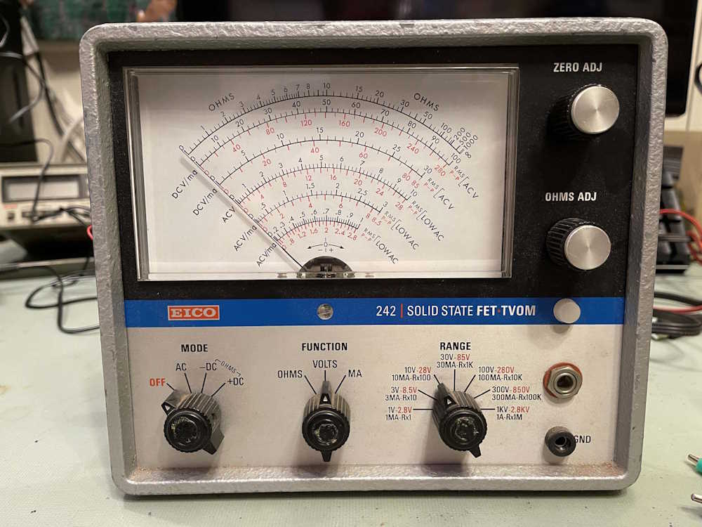
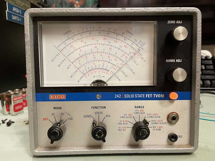
This device came to me from the Columbus Hamfest, another piece from an estate sale. It’s part of my “I can’t go home without a voltmeter” thing, and I figured it’s small enough that it would make a nice bench “no tubes” meter.
It’s built on EICO’s late model transistor chassis, and features everything you’d expect from a FET VOM. High impedance, a big face, and multiple ranges. Oddly absent is a mirror for parallax error resolution, which seems like it would have been a cheap thing to have. Also odd is EICO’s choice of a phone jack for input. There’s some muttering in the manual about that, but it’s just a gimmick from what I can see. Kind of locks you in to their probes. What’s not good about that is the tip is hot, so if your probe gets pulled out live (or inserted live) you can can hit the ring, which is ground. I need to figure out how to re-make this and make it safe(r).
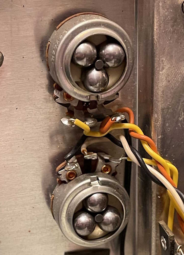
Some of the parts are quite well made. Take these 10-turn ball-bearing pots. These things turn so smooth.
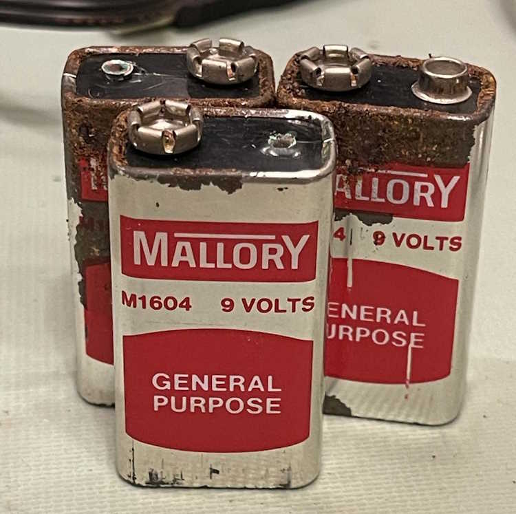
The device can either run on AC line, or 3 9V batteries and 1 1.5V D-Cell. Sort of.
The D-Cell had been removed, but the 9V batteries were still there.
How long has it been since Mallory made batteries? Long enough that these were coated with carbon-zinc rust. Some of the terminals were corroded into the snaps, which is not a big deal. I don’t expect to use this thing on batteries.
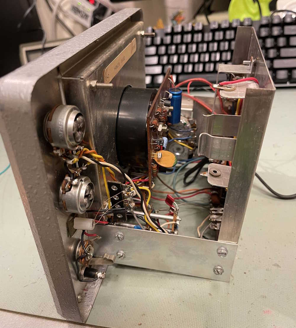
The unit consists of a single board and some parts on strips. It’s really pretty simple, just some differential amps and the FET on the input.
After removing the batteries, I powered it on. DC measurement is off - but there are cal pots inside.
Ohms…that didn’t work. The device stayed on zero and the ohms control did nothing, whereas the zero control slammed the needle to the left. A quick check of the schematic showed something interesting - a 1.5V battery! Turns out this thing NEEDS the 1.5V D-Cell, even when operating off line. I just happened to have one, in it went, and…yep. That works now.
There’s nothing wrong with this save it needs a good warm-up and cal. I’ll probably do that sometime in the next few weeks and get this thing installed on the bench - after I make a probe adapter, of course!
Turned out that there were a lot of out of tolerance, odd-value resistors in the device. I let it go.
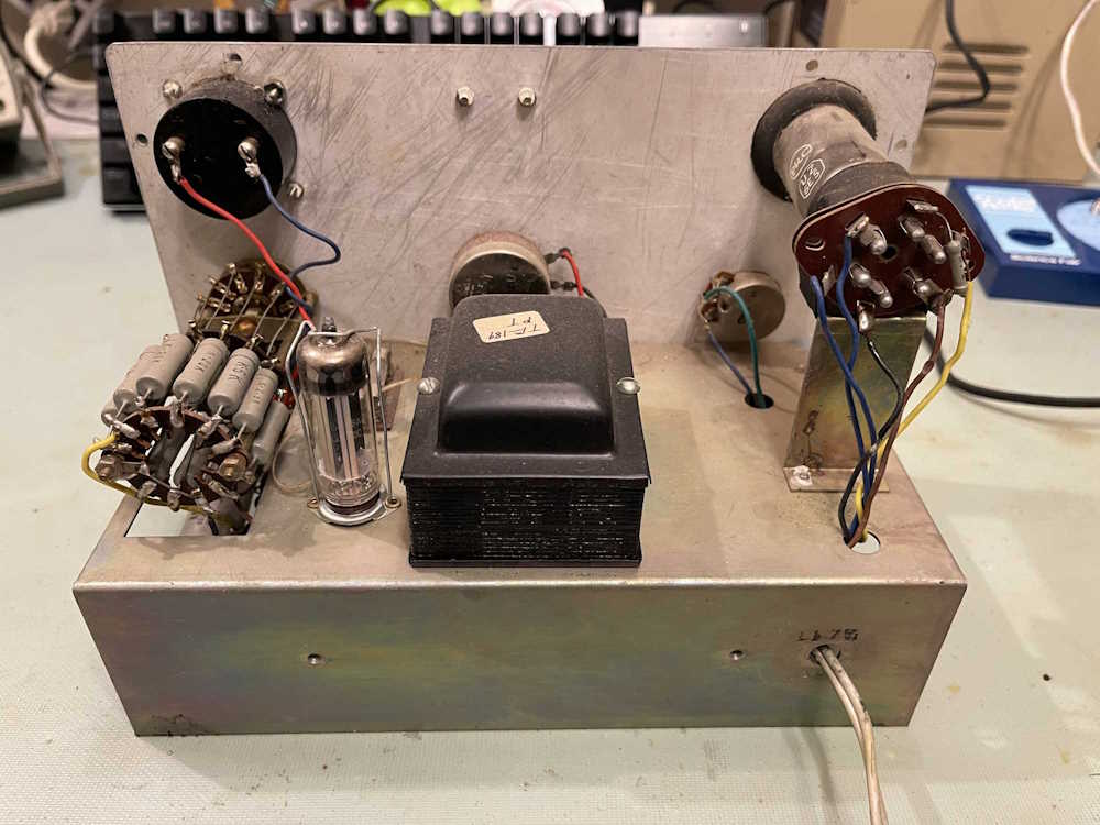
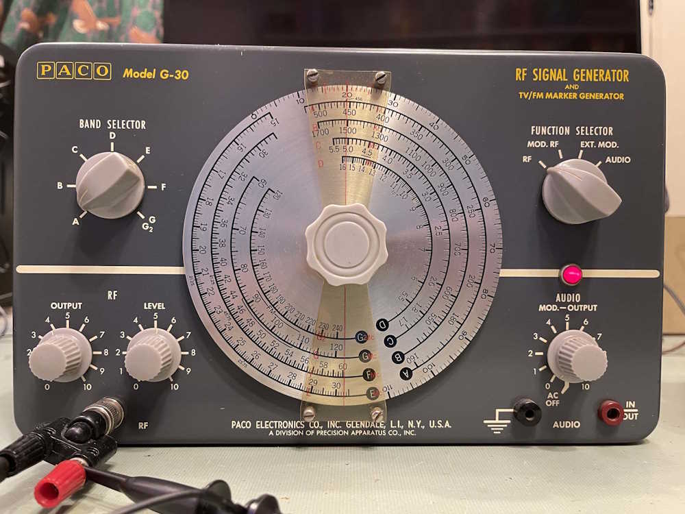
As with a lot of other things, I picked this signal generator up a few years ago at the Cuyahoga Falls hamfest. I seem to remember the person telling me they were using it up until it was sold, as they were trying to clean out some of the redundant equipment.
(Yes, it’s on. I had already opened it at this point to check on things.}
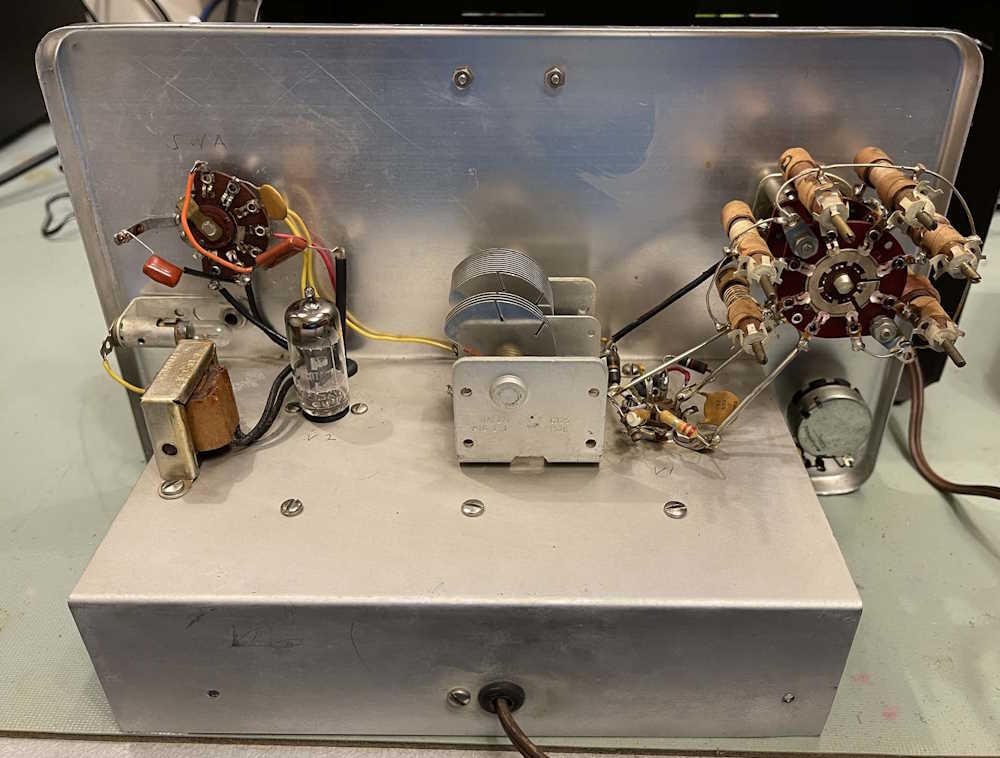
The device itself looks to consist of an oscillator and an amplifier tube. I assume the amp is on top, and the osc is on the bottom (w/shield) but I won’t know until I check the schematics.
Note the selenium stack. It looks like this device has been rebuilt somewhat recently. I don’t think I would have done the capacitors up like that, but it works well enough.
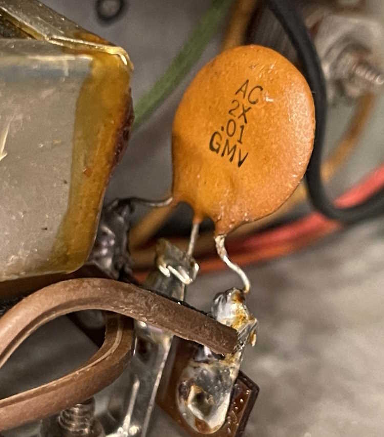
The person didn’t replace two of the most important things, however:
The first being the power cord, which is just as hard as can be. The second is that little disc thing with three legs. This is a safety capacitor, and is two .01µF capacitors back to back. These tend to blow open, as they physically separate, but it’s still a potential problem. Not sure why this didn’t get replaced, but I have two .01µF film caps @ 630V that would work here. If I decide to put it in service, that is. The output isn’t really pretty.
Before you go “That ain’t right” - it may be. In fact, it is. This device uses harmonics to generate it’s output, so you don’t get a signal like you would with a modern, synthesized unit. This is probably fine for an old AA5 radio. I did note that the frequency per the scope is dead on, so that’s a good start.
Stay tuned, this will probably show up again later as a fix it or forget it post.
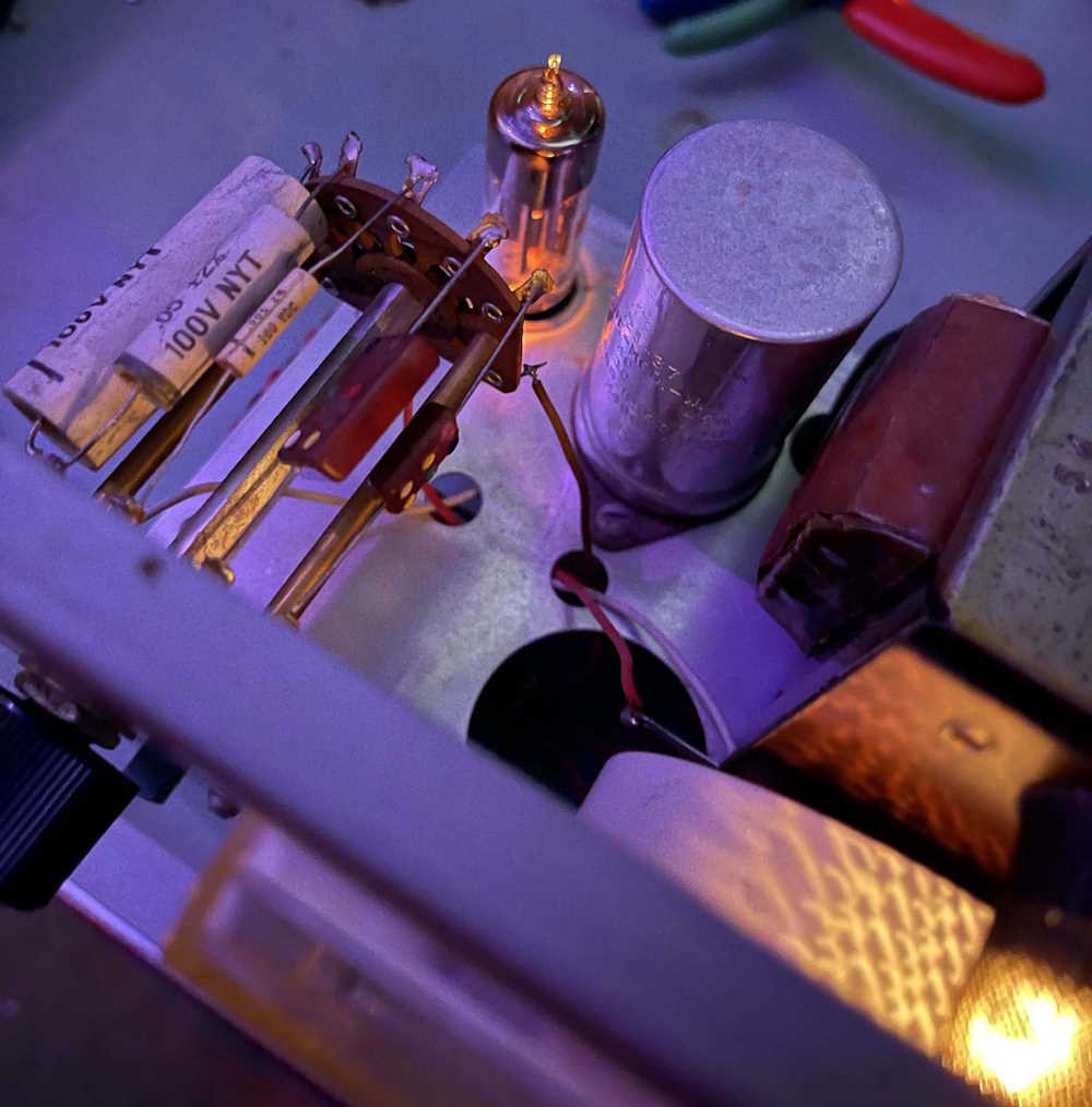
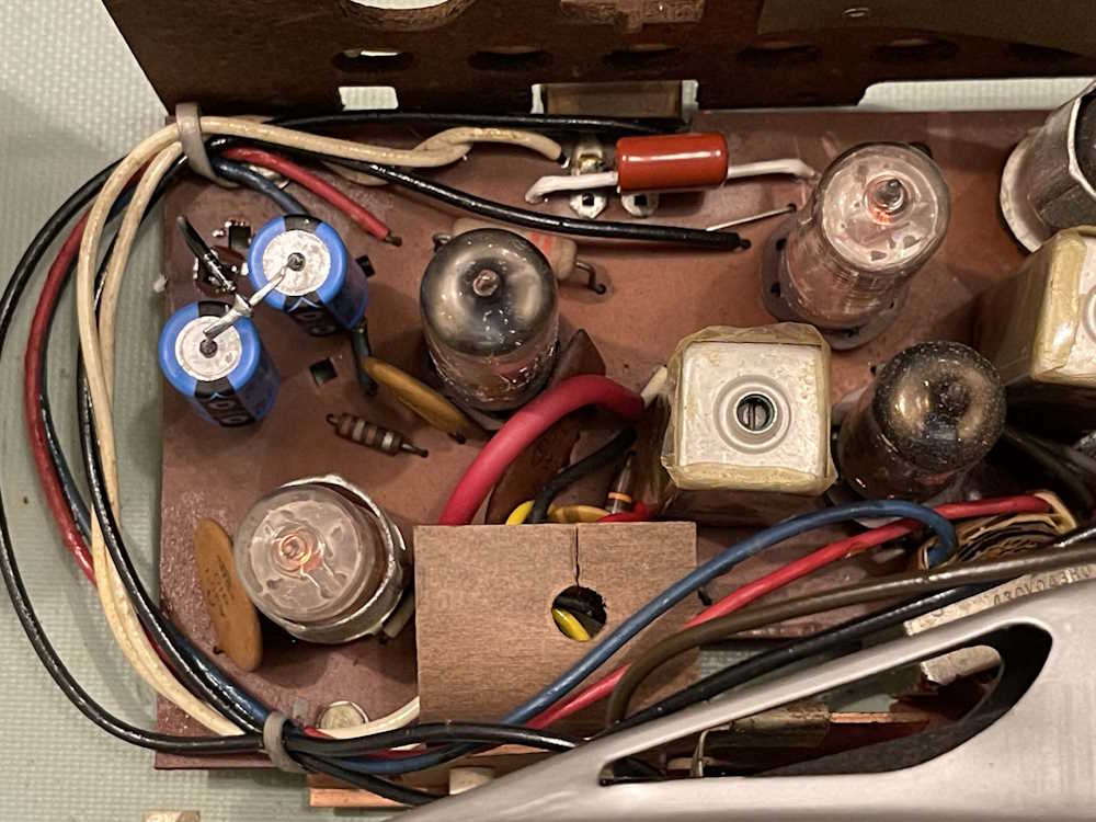
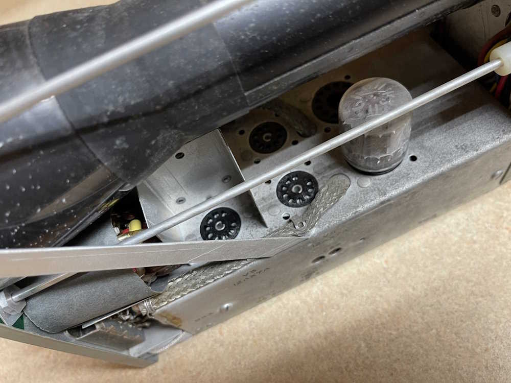
This one was a nice example of a 6 tube AA5 - it has a tuned RF front end which amplifies the RF before it’s brought down to it’s IF signal that the radio demodulates the audio from. That gives it the ability to hear more stations - without any further tuning I was listening to a station 115 miles away during the day, something other radios have a hard time doing during the quieter night period.
Radio came to me not working, seller said “Won’t warm up.” I think the guy just didn’t know that the power was pull on, not turn on. Plugged it in, and bad filters - the characteristic loud 60Hz buzz said that immediately. The replacements are the two cylinders standing up in the upper right corner. Two 47μF @ 160V replaced the 40/40@150 there previously. That device was dead, high ESR and loss, and cracked potting.
That brought the radio back to life, but the across-the-line capacitor had to be changed as well. That’s a .047μF @ 630V that literally sits across the AC line, and helps reduce noise in the system. That’s the orange-red rectangle in the middle, a brand new film cap with it’s leads covered in spaghetti to keep it off of the AC below.
These go bad just because they have a lot of voltage on them, and age - the part in there was a type of capacitor called a bumblebee. They’re BumbleBombs now because they like to pop. Fine for the time, but they crack and leak and get moisture in the paper capacitor material, and go boom.
The radio with all of its new parts. I tried to not disturb anything else. (That recent spaghetti purchase has been used a lot!)
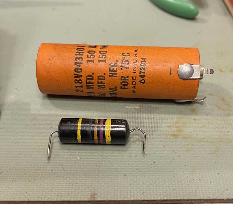
Here’s the old parts. The bumblebee measured ok, but I didn’t do leakage. The electrolytic was dead, however. Notice how the leads on the ‘bee are bent weird? That’s how it was in the circuit. Someone hand-inserted the part decades ago and said “eh…good enough!”
The only thing it really needs at this point is a little bit of penetrating oil on the tuner, as it’s gritty - a flush clean with DeOxit helped, but some Kroil is in order here. It probably needs an alignment, not a big deal but that’s after the tuner is cleaned, and it needs the dial lamps replaced. Power cord could be changed as well, but since it’s one of those in-the-case style it’s going to need a bit of doing. I may just solder a new cord in the board and run it out the hole.
In all, it was a good find in my opinion, a nice clean example of a AA5, late enough that silver mica disease hasn’t taken over yet. It’s getting harder to find this kind of radio in good shape, so as soon as the lubricant arrives and I get it tuned up, it goes on the shelf in the living room for use.
I don’t know that there will be much for a third part, except to talk about how far off the alignment is. We’ll see, stay tuned!
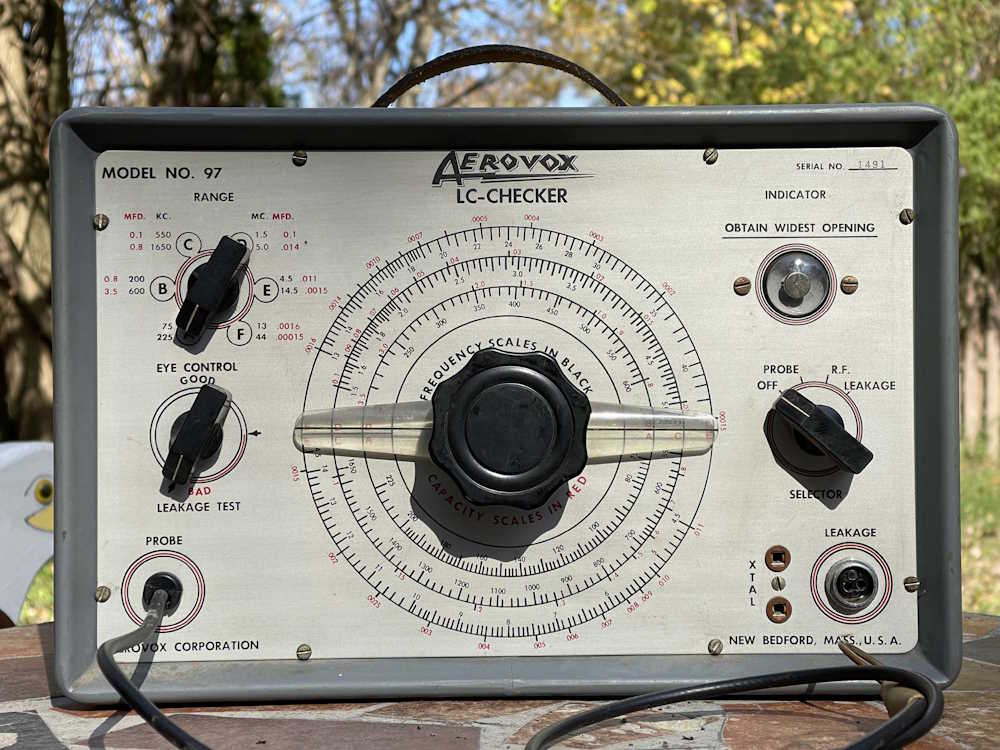
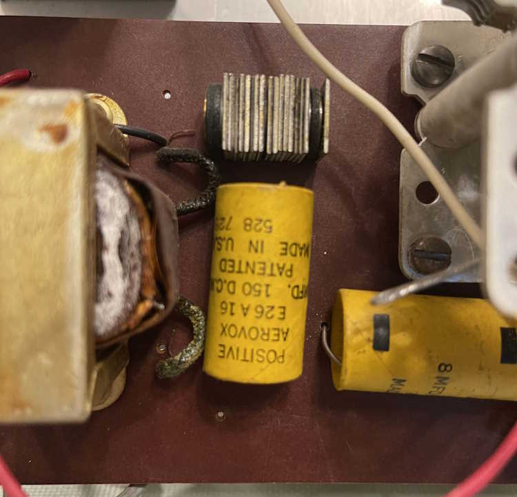
This interesting piece came from the 2024 Cleveland Hamfest for $5. The vendor was selling an estate - that seems to be happening a lot lately - and was just looking to return some cash to the estate itself. He knew nothing about the unit, but I took a chance and picked it up.
Aerovox, of course, is a name you’ll probably see on capacitors in older devices. The name Aerovox is still out there, but it seems to be more of an industrial player instead of a consumer devices company.
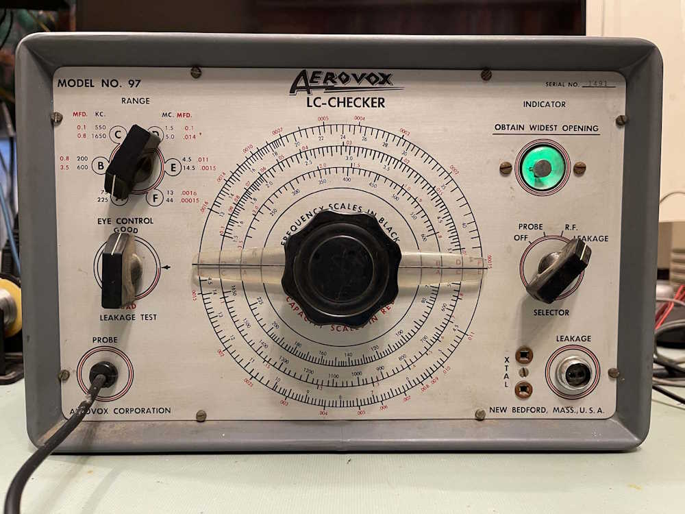
The device seems to be fairly standard at first glance, with your normal ranges and dial to tune to the unit under test.
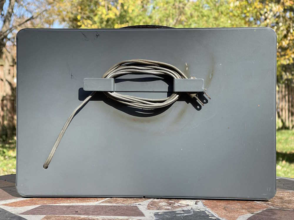
Nothing special about the case.
The back does have a nice cord wrap area, and the cord seems to be still soft.
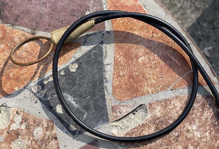
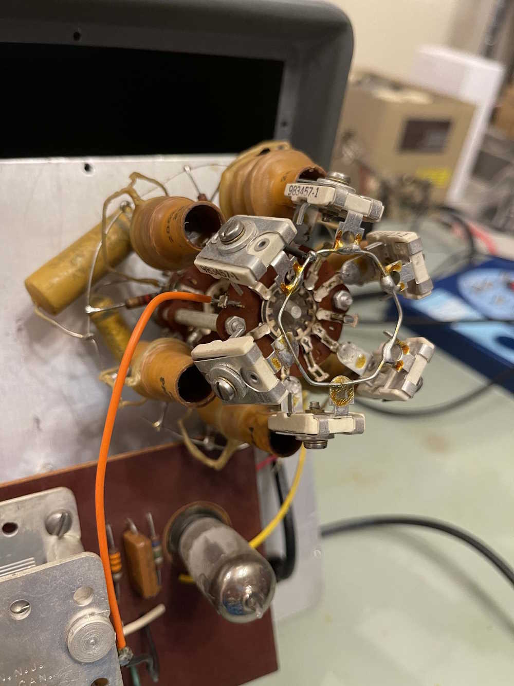
The probe is the most unusual part of this device, and is a deal-breaker for using the thing.
Its an inductive probe - there was another piece that went inside this loop of copper, so you could make a part connection without actually connecting the electronics of the tester to the part itself. This is kind of cool because it avoids hitting a live or charged device, but it’s also missing the business end of the probe, so the device can’t read anything. I’m sure it could be modified to work, but I have enough checkers already…
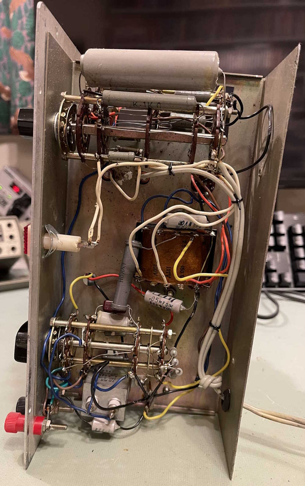
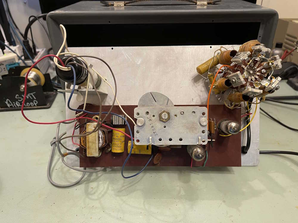
The inside is pretty sparse. A big selenium stack, some capacitors, and the oscillator section for actually checking parts. The big banana slicer in the middle dominates everything.
The device does come alive, and switching things makes the eye open and close.
But…that’s about it. Without the probe, it’s nothing more than a shelf queen - or parts. Fortunately, I have someone who would like a display piece, so it goes to them instead of the parts bin.
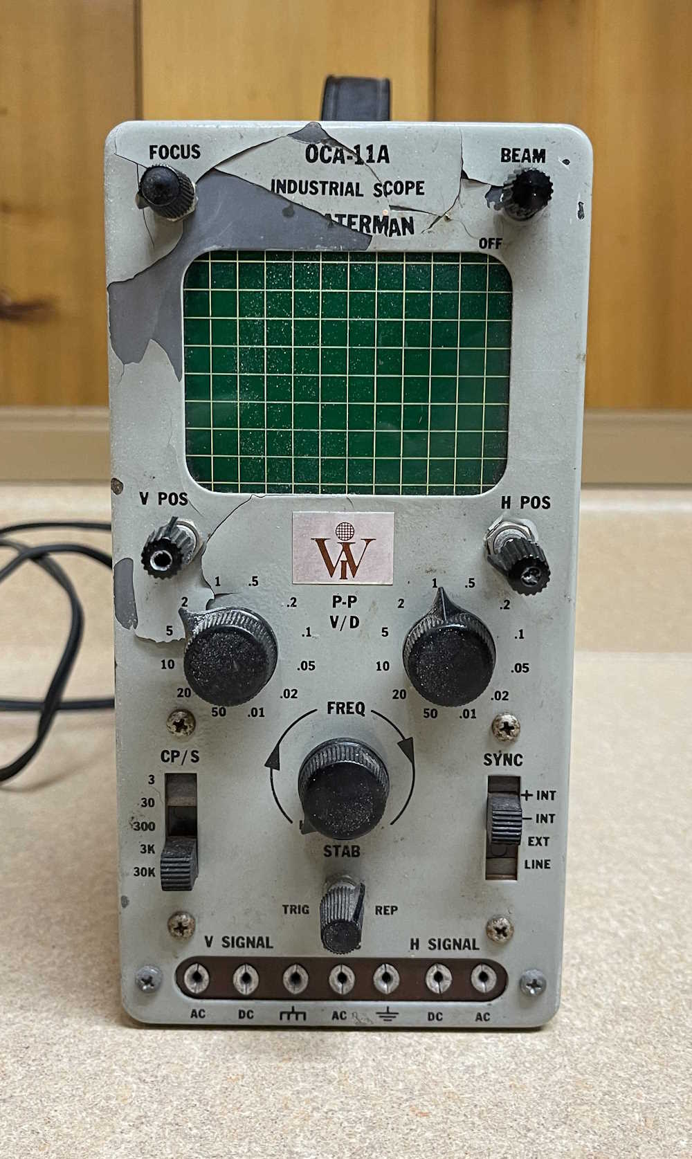
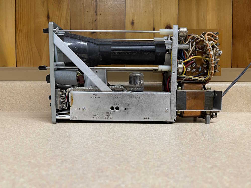
This little scope came from the recent MARC hamfest, and was sold as not working - the previous owner stated that someone had removed tubes, and all he did was verify the heater in the CRT was lighting up. He was right, someone removed all of the 12AX7 tubes as well as a 6U10 compactron, leaving only a 6AG11 compactron in place. All of these devices are triode amplifiers, with the 6AG11 having two diodes in addition to the triodes.
The device appears to have a solid-state power supply with solitary diode. There’s some small evidence of repairs being made over the years, but for the most part it seems to be fairly original.
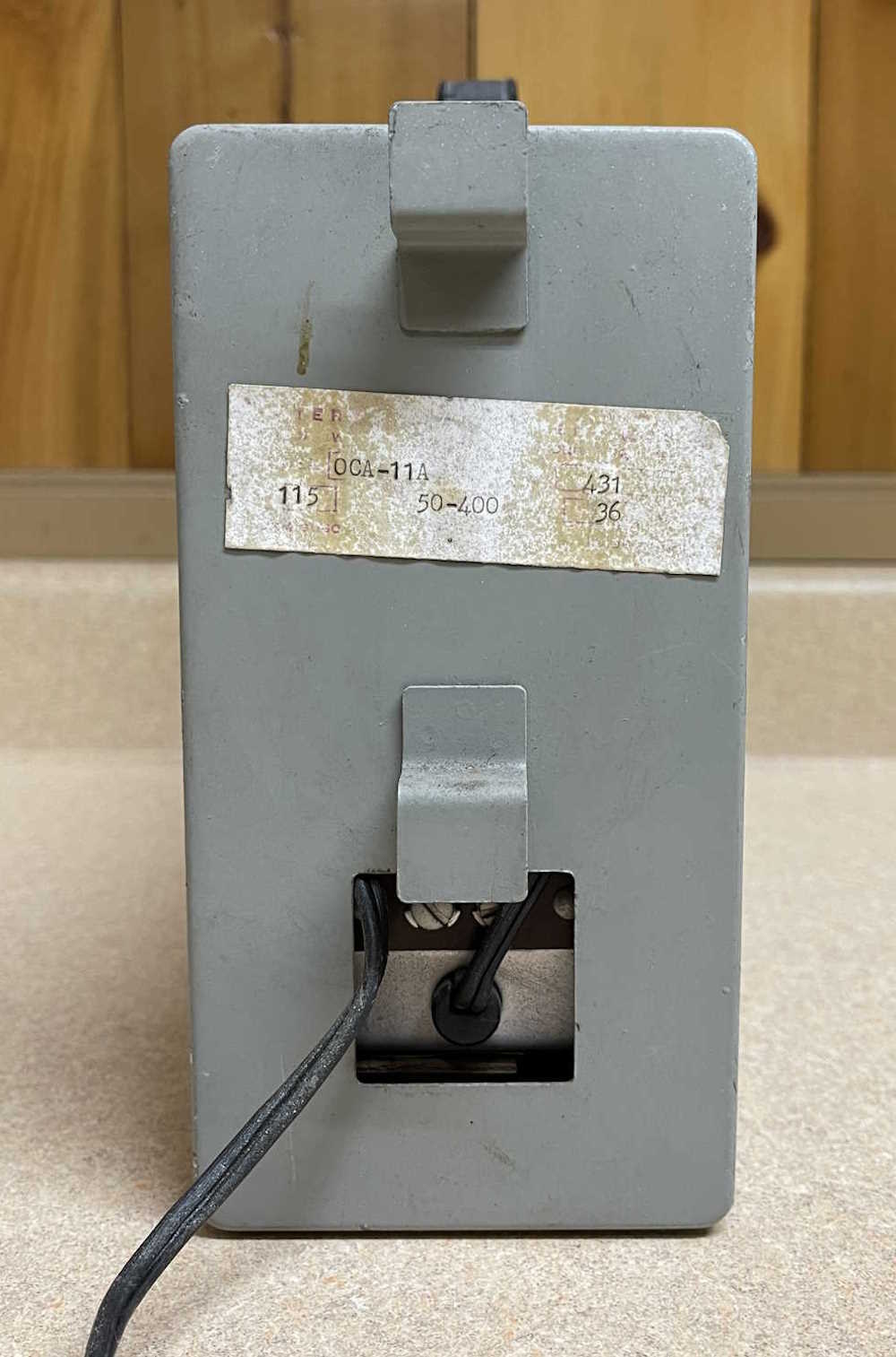
The device is capable of operating on 50-400Hz @ 115VAC
The front offers all the controls, and uses pin jacks for input on a strip at the bottom. That’s kind of unusual. The metal under the paint appears to be oxidized, and the enamel with the lettering is flaking off. The potentiometers are brought out to the front by long internal shafts, some of which are bent. This could be an easy fix, as they’re just connected internally with nylon unions.
The back offers a cord wrap and some screw terminals, presumably for grounds. It also offers a badly exiting cord from the previous owner.
The device is relatively clean inside with the transformer, power supply, and high voltage all riding in the back.
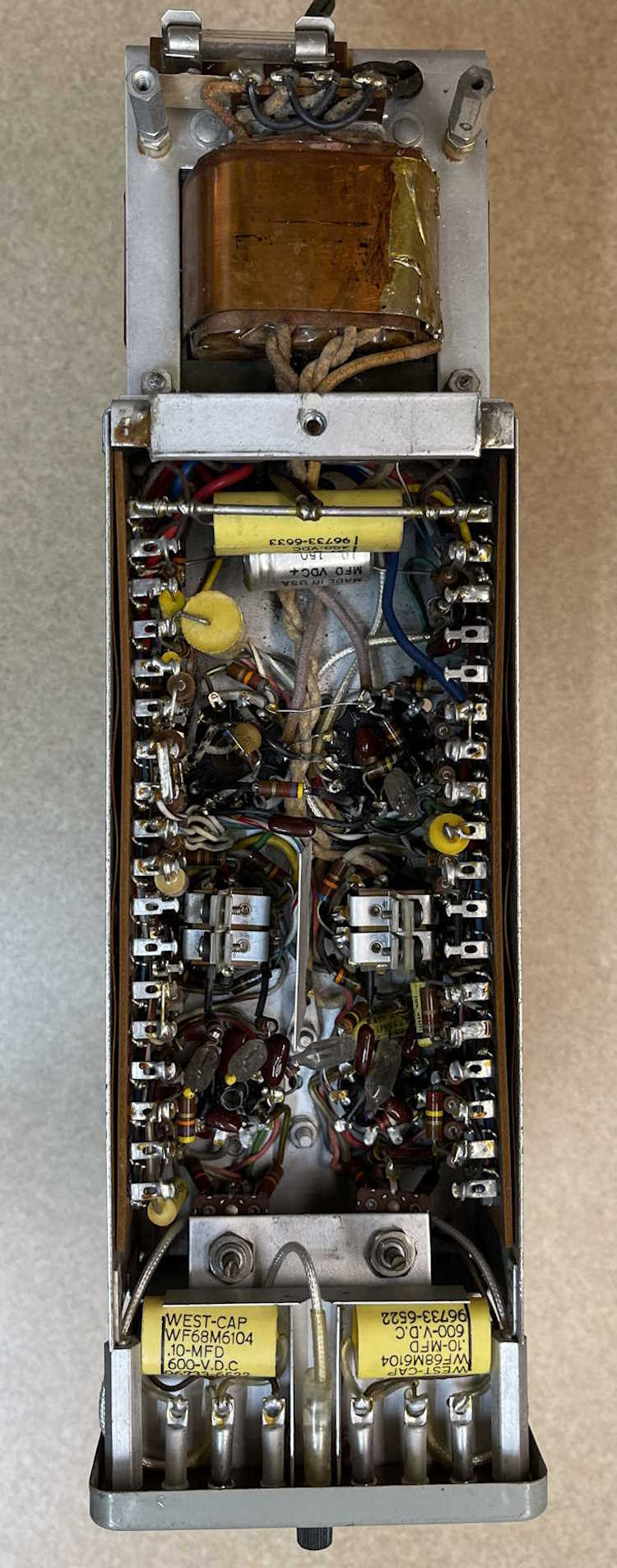
The bottom is well packed, but there’s no wax paper stuff as far as I can see. Looks like films and other decent capacitors, but I bet some of those carbon comp resistors are drifting. There’s an electrolytic that’s probably baked out, and some neon bulbs of unknown type probably being used as regulators that would need to be replaced, but that’s about it.
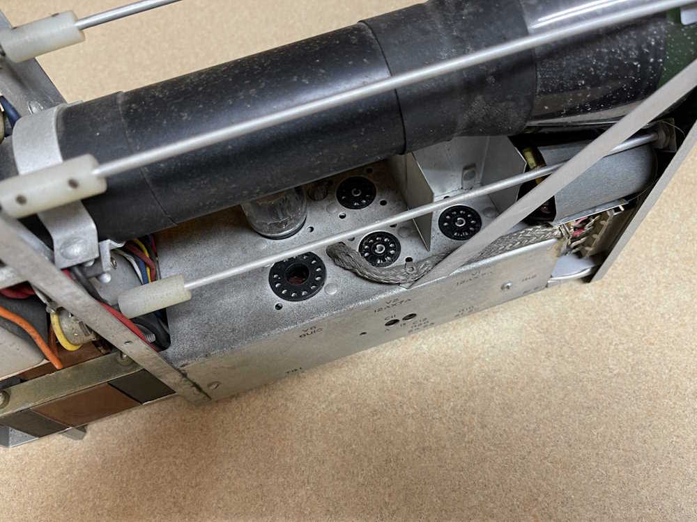
You can see where the previous owner removed all of the “good” tubes. The 6AG11 is also a triode pair, so I’m not sure why they didn’t remove it as well. Fortunately, if you’re not concerned about the make of the tubes, all of them can be relatively cheap - there’s about $25 worth needed for this device.
It’s an interesting little scope, and would be perfect for a benchtop radio repair station - tube scope with tube inputs doesn’t care if you hit B+ for a second.
I think I may give it a shot and see if it will live again. If someone out there has a schematic for this unit, I’d appreciate a copy.
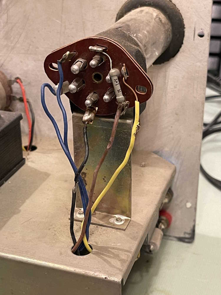
I was warming the device up for final cal. I had just completed it, and put it back in the case. Back on and SNAP.
I did some measurements. Nothing much of note. Removed the tubes, applied power. ZZZZZZZ right on the socket for the 6X4 cathode. WTF???
I removed the wire from the cathode to the filter capacitor. Nothing. I reconnected it to the choke. A nice spark was jumping from one of the plates to the cathode. Removed the wire on the cathode and did a measurement from cathode to plate pins.
There’s nothing connected to this pin other than my meter. 60Ω is not a good measurement. It came and went as the pin was moved around.
It looks like this double-wafer socket may have some carbon tracking inside of it. Oh fun! That means trying to figure out something to replace it. I have some sockets in stock, we’ll see if there’s one that can be used here.
Of course I don’t have the correct socket - these are 1” mounting centers, which is an oddball size. Most are 7/8”. Off to eBay for the rescue!