Stabilizing the oscillator in the IM-1212 Meter, part 2
Monday, January 8, 2024 at 08:35:07
One of the issues with the IM-1212 and it’s clones is that it drifts all over the place, and part of that is the oscillator that actually does the counting for the display. This is an attempt to replace that section with better parts to see if it’s any more stable. I started this with this previous post, and present my findings here.
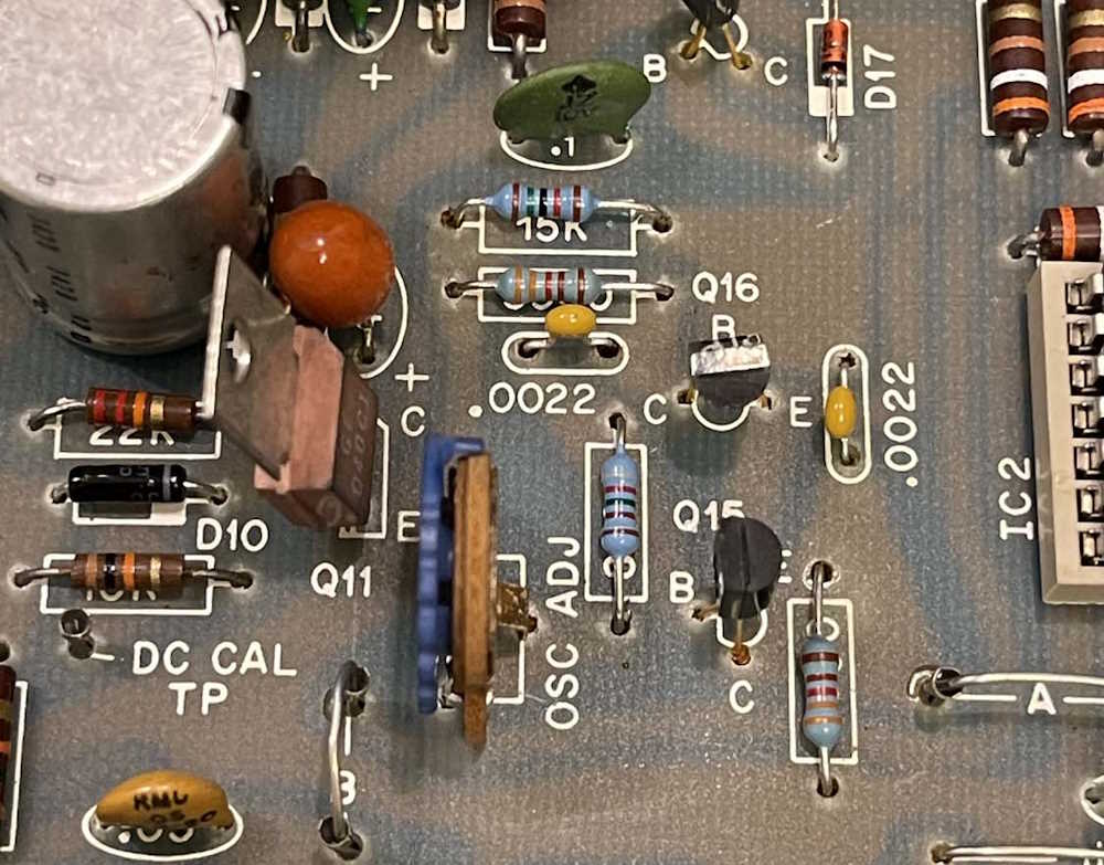
We start by identifying the components of interest and removing the board:
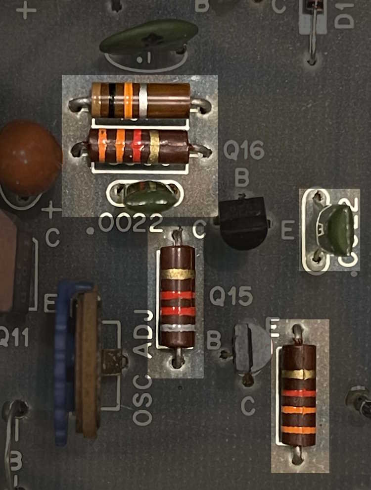

In the oscillator circuit, other than the transistors, are the following passives:
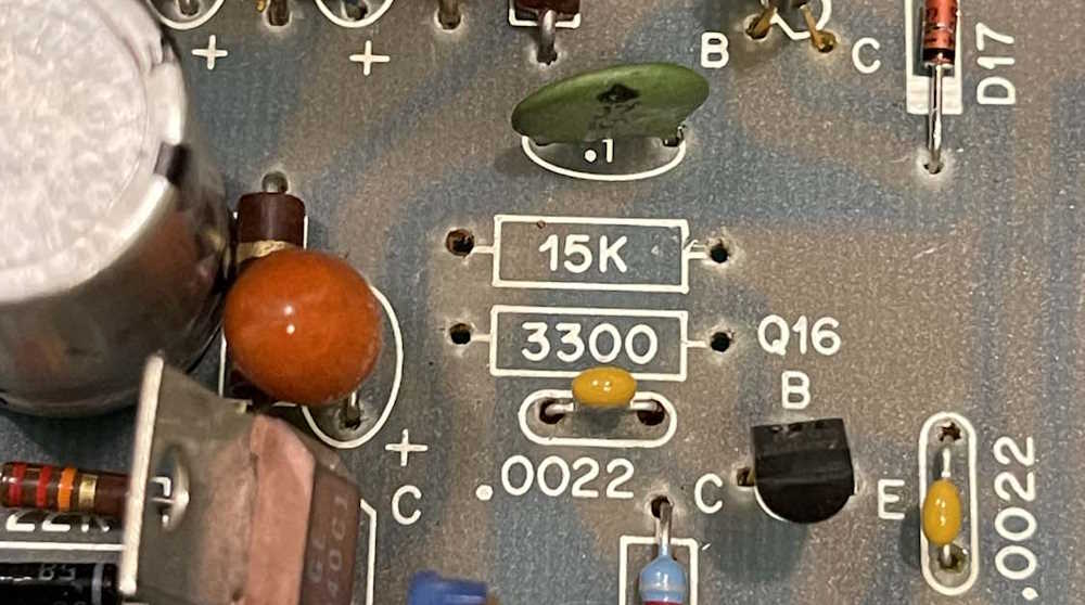
15k
8.2k
3.3k
3.3k
0.0022uF
0.0022uF
15k Potentiometer
We’re not going to replace the pot, but all of the other components are going to be replaced by film and/or temperature stable to 25ppm components.
The sharper-eyed among you will have already seen an issue. There’s no 15k resistor identified here, and I’ll talk about this a bit later in the process.
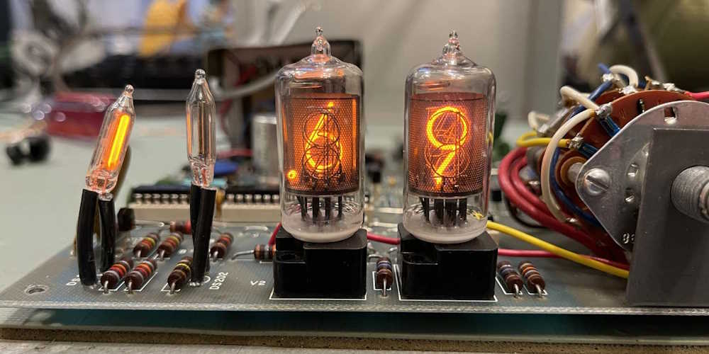
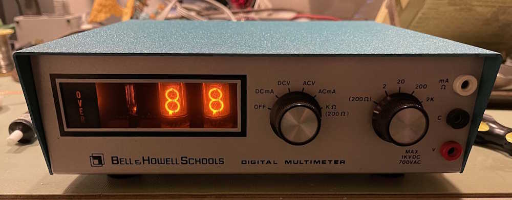
Before taking the board out, I let it warm up and preset the oscillator to it’s suggested 85 count.
Getting the board out isn’t too bad. There are 6 screws, three solders, and a clamp.
The screws are the ground lug for the power cord on the back panel, the two screws that hold the transformer down, and one screw each in the remaining corners. One of the screws is under the switch assembly and can just be seen by the red input jack, so you’ll need something relatively thin and long for this one. They all appear to be the same size.
Next are the three jacks on the input. I unsoldered these at the front panel itself, but the white wire was long and flopped around and broke because it is solid wire. Not a big deal there.
Last, is the clamp for the power cord on the back panel. This is just squeeze it with pliers and work it out. I left the power cord attached to the unit and just pulled it through the bottom case so I had enough room to work, and used the ground lug screw and nut to temporarily hold the transformer down as not to break the relatively fragile connections to the PCB.
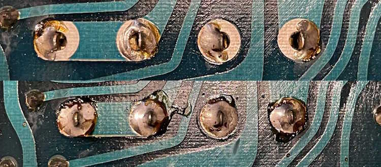
Before getting started, I did an inspection of the board. There were a number of bad solders on some of the components - mostly things with thick leads like the potentiometers. I took a minute to clean those up before getting started.
Removing the parts is relatively easy, this being a single sided board. A soldapult and some wick made short work of the old solder, and that’s when I noticed the 15k resistor wasn’t.
The schematic indicates 15k, as does the board - and another unit I have has the correct 15k part in it. I have to wonder why this was there - did the original builder not get the correct part, or was it broken during assembly? Who knows - but it didn’t really matter as the device worked.
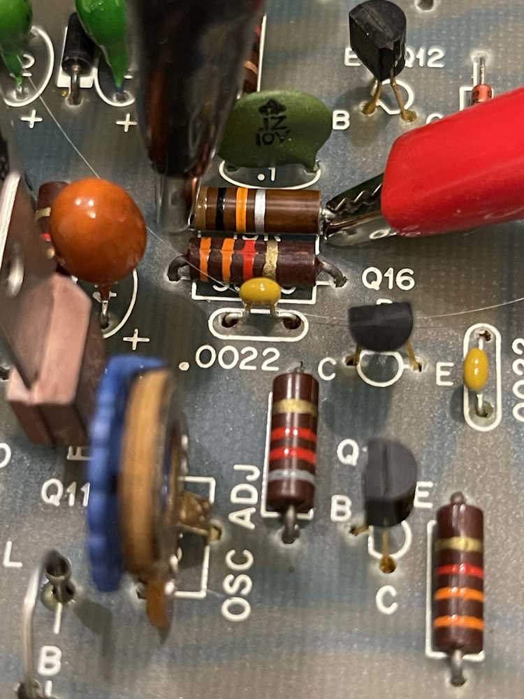
Interesting.
The rest of the parts are replaced without issue, and the correct 15k is placed where indicated.
There’s not a lot of current or voltage here, so I wasn’t particularly concerned with the size of the resistors.
After doing a precursory check of parts, solders, and whatnot, I powered the device up on the bench. The oscillator count was quite different, so my replacements had some effect.
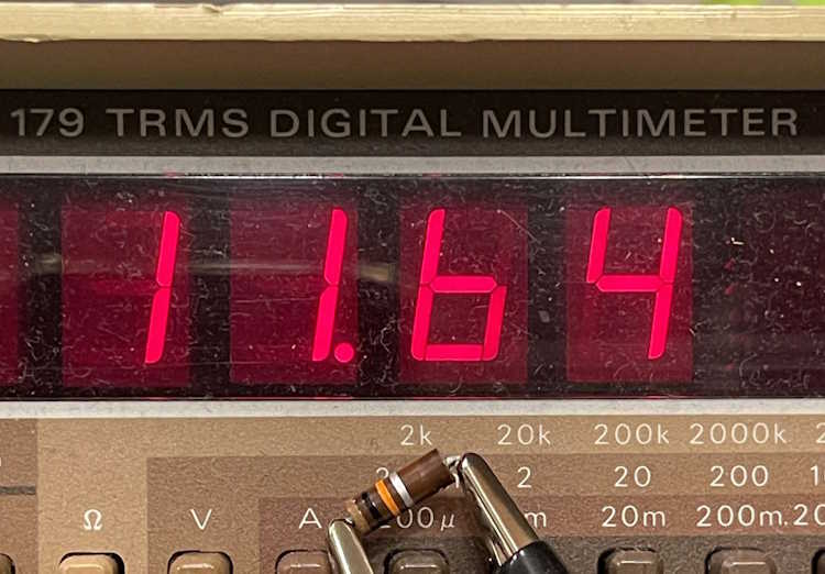
Some warmup time later and I adjusted the oscillator to the correct value:
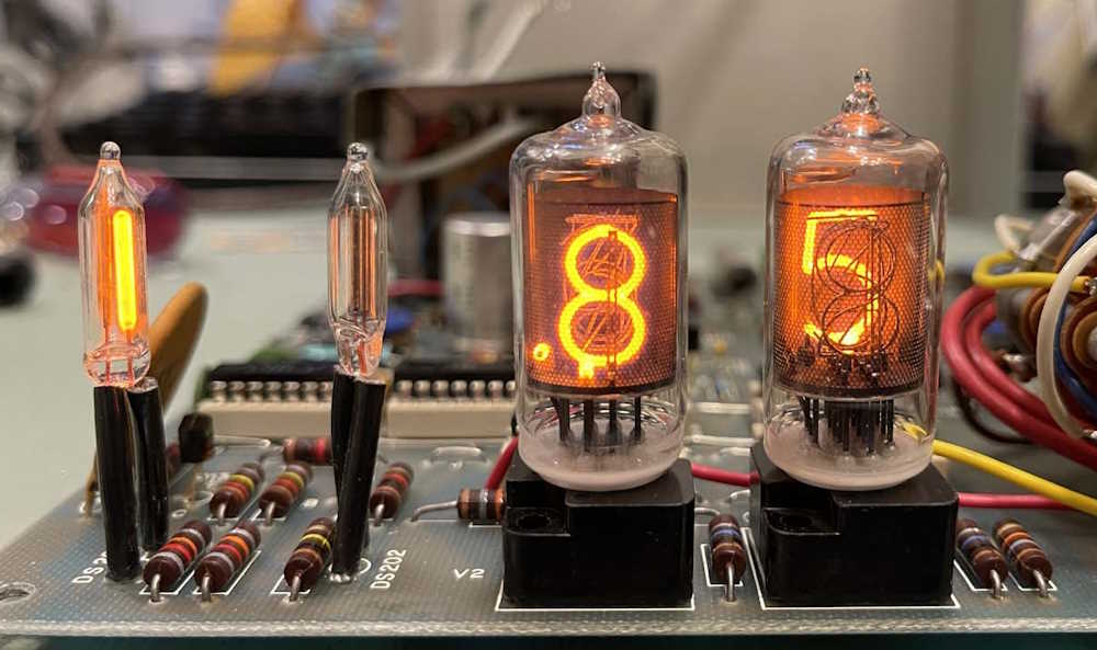
Putting it back together and:
It’s already drifting. I set it back to 85 and let it set until the next day.
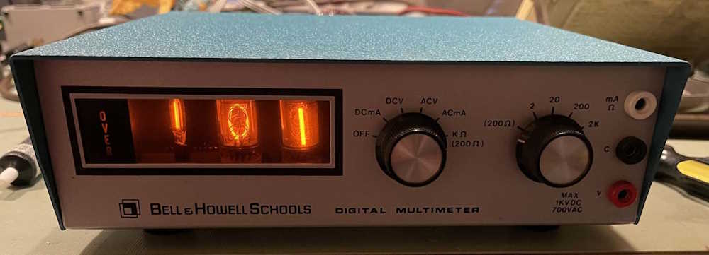
It didn’t do a thing. I will say, however, that it seems easier to adjust it back - there’s not as much play in the overall adjustment - you can set it and it generally stays there until the temperature changes.
So, my conclusions? This whole thing probably would need rebuilt with modern components in order to maintain any stability in measurement. For now, it’s just going to be sitting in a rack on all the time measuring the 12V rail of a power supply so … it is what it is, I guess.