An Eico 145 Signal Tracer - Part 6b - Continuing the power supply.
Sunday, September 29, 2024 at 11:32:12
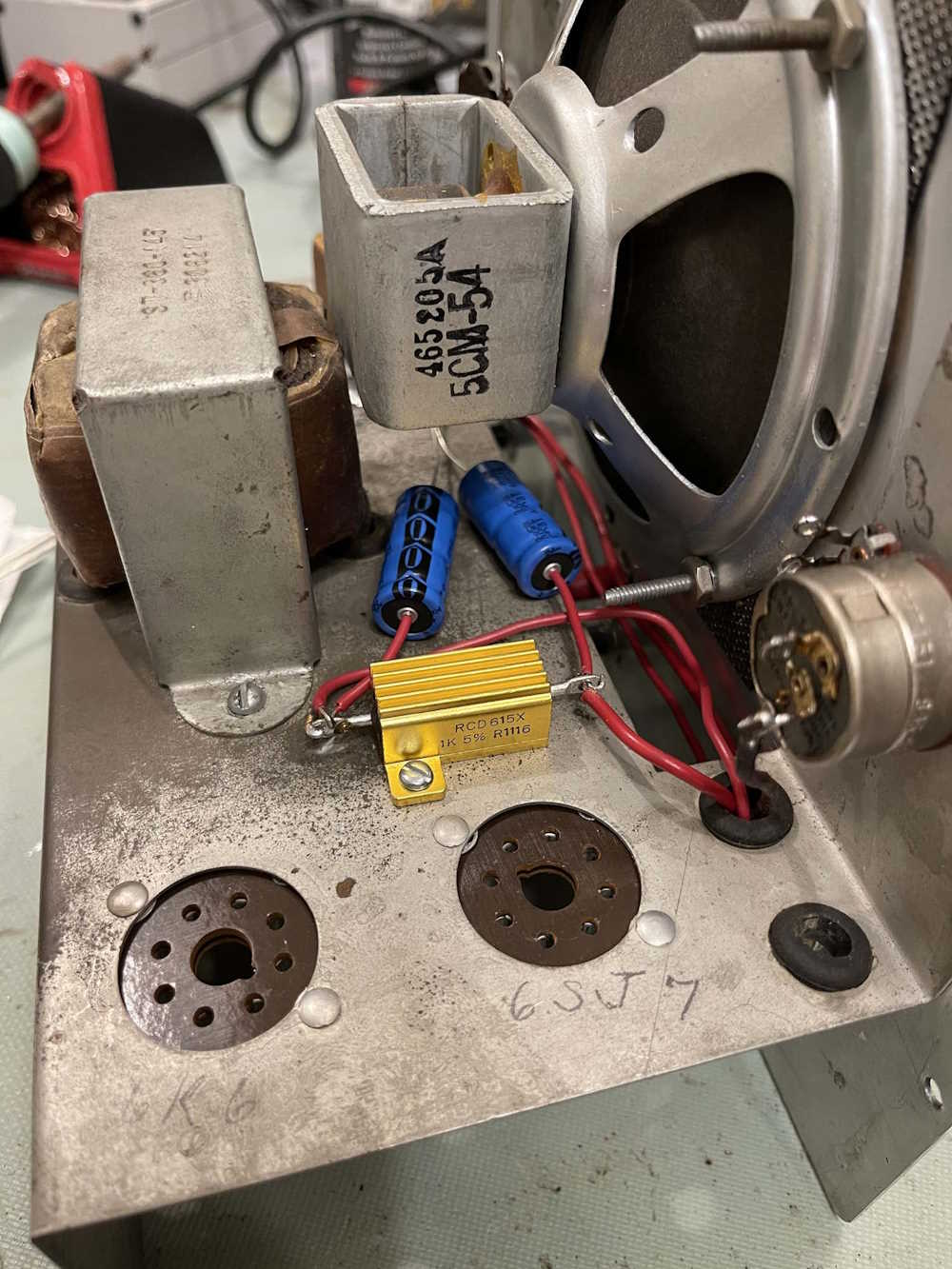
I had to make some executive decisions in where to place things here, since I have more going on under the chassis. Instead of using a leaded device for the power supply dropping resistor, I chose to use a non-inductive aluminum cased resistor. Is a 25W resistor overkill here? Yes it is. Do I care? Not at all. I also moved the filter capacitors on top of the chassis since the old device with it’s mount clip is now gone. Two holes were drilled to mount the resistor - theoretically this should sink into the chassis as well, but the resistor is more than capable of dissipating the 2W the original was designed for without any heatsink at all. One side has the connection from the rectifier and a filter capacitor, the other is connected to the output transformer, and will run to various points in the circuit itself.
The only thing left to connect to the filters is that second connection, then it can be soldered.
Will this cause some hum? Maybe, but the audio output transformer lead was already as long as it is now, so who knows.
(There’s lots of hum in this unit, so I didn’t really care about this kind of layout. The audio input line is essentially a giant antenna that stretches the entire length of the device, so - yeah, whatever it is, it is.)
You can see the filters, laying against the chassis, going to a ground point near the output transformer.
I also connected the grounds at the input, and soldered one side of the 50pF capacitor down.
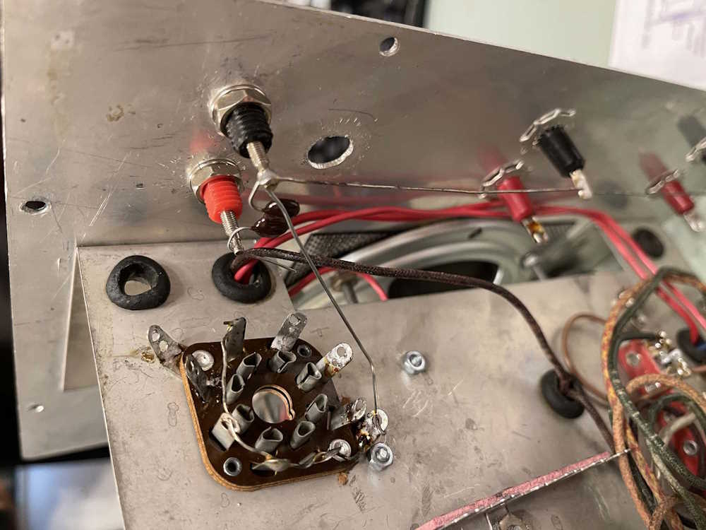
(I don’t know why I ran that wire from ground like that. I’m a stupid wereboar and got rid of it later.)
Last, is the ground point on the audio output transformer side. The transformer itself is a little smaller than the holes drilled, so was this a replacement? No idea, but I went ahead and drilled a new hole for it so it’s not flopping around on the chassis. The original transformer mount hole had a small ground tab in it, I went ahead and recycled one of the terminal strips from the bottom as a ground. This point has both filters, the speaker, and the output transformer connected to it. Since this is a fairly important ground, I hit the chassis with some scotchbrite and soldered the tab in place, insuring a nice, solid connection.
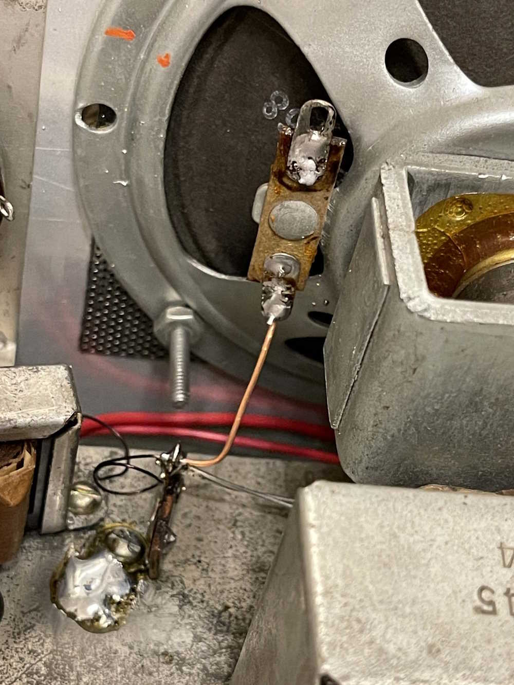
There’s a bit of solder splatter there to clean up.
You’ll notice that the output lead for the transformer is coiled up. I’ve been trying to avoid trimming any length from parts left on the chassis, just in case.
Just to note, I am in no way concerned with making this look original. It’s going to be a working device, and that’s it. I’ve tried to select good parts, so barring tube failure this thing should work for many years - and I may just get a set of tubes regardless to populate the device when it’s ready for service.
Stay tuned for part 6c, a few more connections and we’ll test the power supply!
Next part of this series: https://wereboar.com … -to-run-a-few-wires/
Previous part of this series: https://wereboar.com … tarting-the-rebuild/
Wrapup and link to all posts: https://wereboar.com … -and-final-thoughts/