An audio analyzer project idea from years ago.
Thursday, October 10, 2024 at 07:05:17
A long time ago, I had an idea to make a 10 band audio spectrum analyzer out of meters. I’d use a pre-existing circuit from another device for the band filters, and then rectify it using precision rectifiers. Some other glue circuitry was needed, but I don’t remember everything that was planned for the device.
I couldn’t find enough of the same kind of small meter I wanted to use, so the project got shelved. Eventually, I got rid of the big audio system and no longer had a need for it - but it’s kind of a neat idea and I would still like to complete it. Seeing as how eye tubes are available from overseas sources at a decent price, it may be interesting to revisit this with those instead of meters.
There were four board completed for the project before I didn’t have need for it anymore:
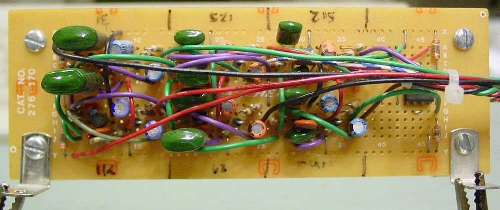
This is the board for the lower 6 bands of a 10 band unit. They’re simple wide-band bandpass filters with a center loosely around the frequency of input. The more eagle-eyed among you may recognize this circuit from that Radio Shack graphic EQ with the multicolor LED display that they sold in the early 90s. It’s right out of the service manual for that device.
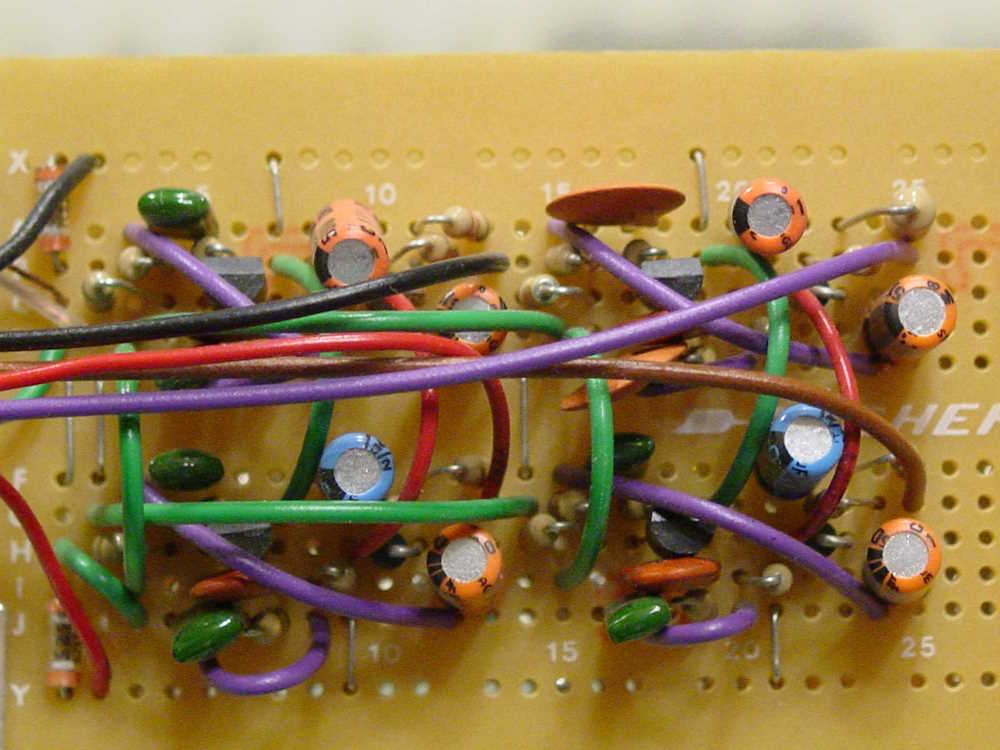
This is the board for the upper 4 bands. Same as the lower 6.
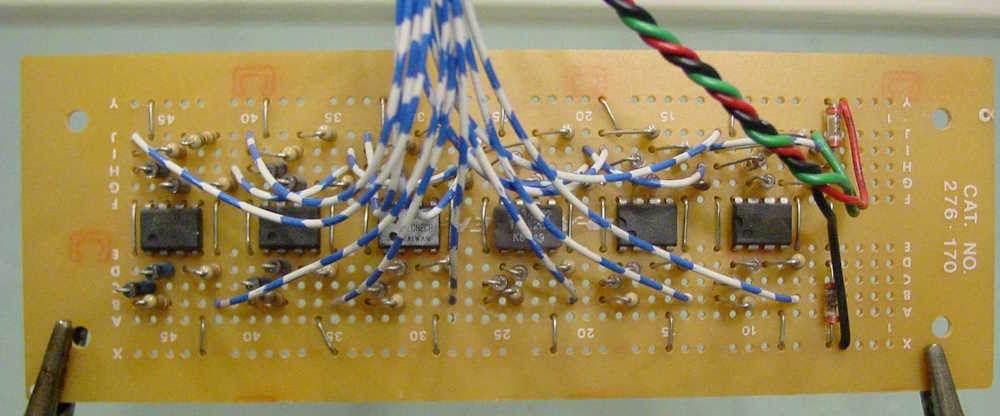
This is the lower 6 band precision rectifier. They’re all full-wave bridge rectifiers with an op amp to provide gain for the circuit so that it combats the drop of the diodes. Ge diodes were chosen because of their cheapness (at the time!) and their relatively low voltage drop and fast recovery. This was to provide DC for the meters themselves, which would be directly driven by the output of the op-amps.
1N34 aren’t really cheap these days, but you can still get big packs of them from auction sites relatively cheaply if desired.
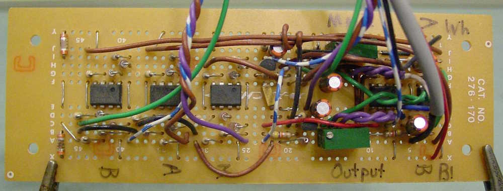
I really don’t remember what this board was supposed to do except combine the two inputs at an equal rate. It was going to be doing some other stuff as well, as evidenced by the remaining circuitry - but I can’t remember what that was supposed to be. I’d probably just set this aside and spin up a new precision rectifier and input board if I were to re-start this project.
That’s as far as I got before shelving the unit. I think I’ll revisit this over the winter.