An Eico 145 Signal Tracer - Part 7 - On the importance of checking your work.
Sunday, October 20, 2024 at 18:26:04
Always do it.
Tonight I sat down with the Eico 145 and ran through the schematic, checking all parts. I found 2 errors.
1. The B+ line wasn’t run to the junction of of R3/R4 for the 6SJ7. This is my oversight, I remember looking at that and figuring out how to lay it out. There was an awful lot going on on the same connection to the 6K6, and I forgot about it.
2. R2, the input to ground resistor for the 6SJ7 was a 510k. I have no idea why I did this, I wrote down “order a 10Meg” and didn’t. That’s not a big deal, I just need to grab one from somewhere. I don’t have any, so I’ll probably just order a few from Mouser next round. That’s a decent value to have around for tube stuff.
Now for show and tell…
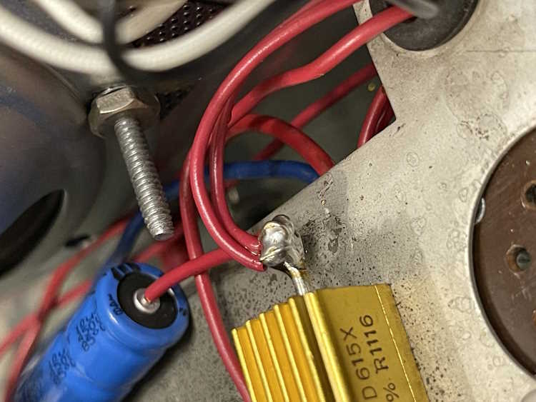
You’ll notice there are now 3 wires on the B+ side of the device. 1 for the filter, 2 for the feeds to the unit.
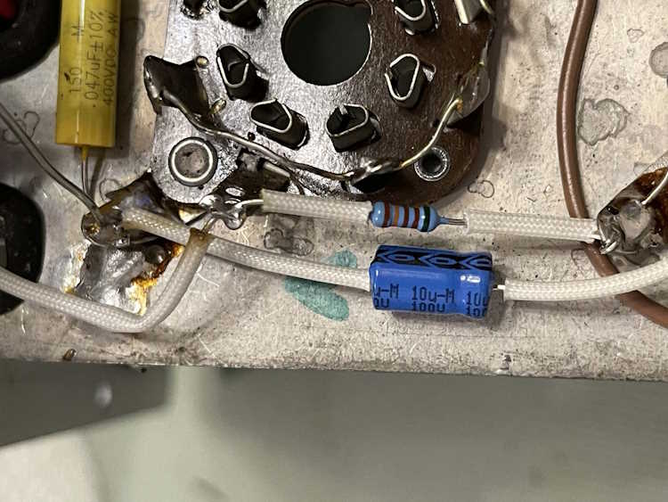
You’ll notice that’s not a 10Meg resistor.
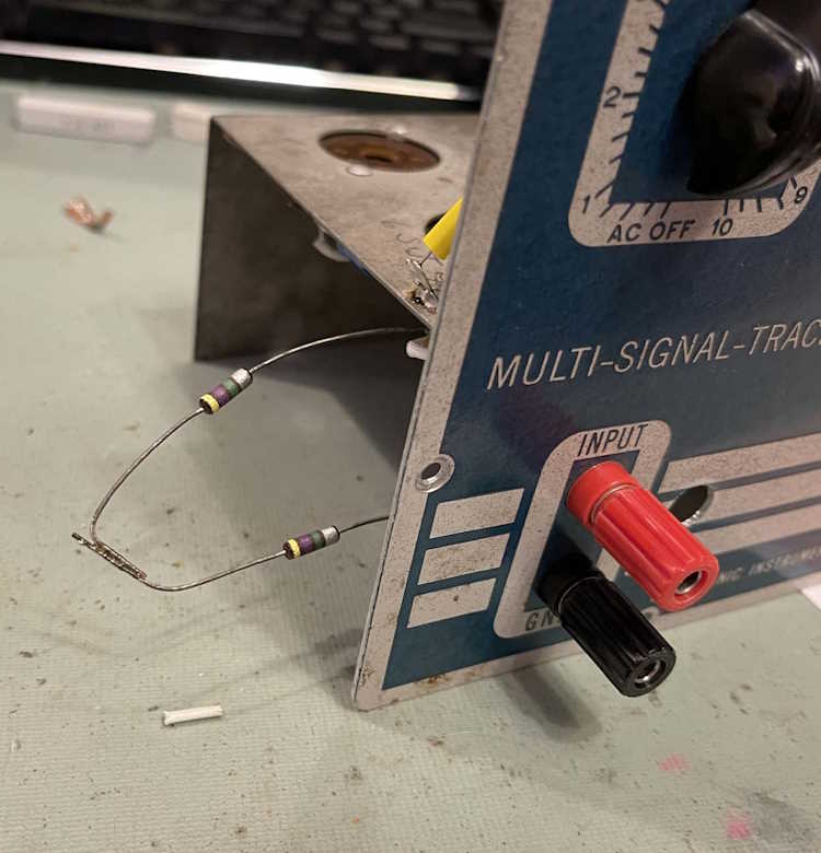
I had two 4.7M carbon comps. They make 10ish megs. They’ll work to test the unit.
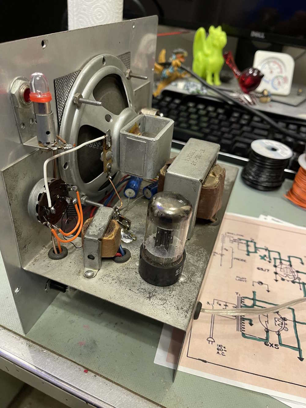
With all of the wiring matching the schematic, I put the rectifier in, plugged it in to the isolation transfomer, and hit the switch. The rectifier lit and B+ went to 393V. That’s good. Filaments at 115VAC are running around 6.5VAC. That’s not ideal , but better than the 7+ it was hitting before the diode mod. It may need some more diodes, I’ll consider that later.
With all of the first voltage checks good, the next step is going to be putting in the rest of the tubes and seeing what happens. Stay tuned!
Next part of this series: https://wereboar.com … art-8-and-were-done/
Previous part of this series: https://wereboar.com … the-rebuild-is-done/
Wrapup and link to all posts: https://wereboar.com … -and-final-thoughts/