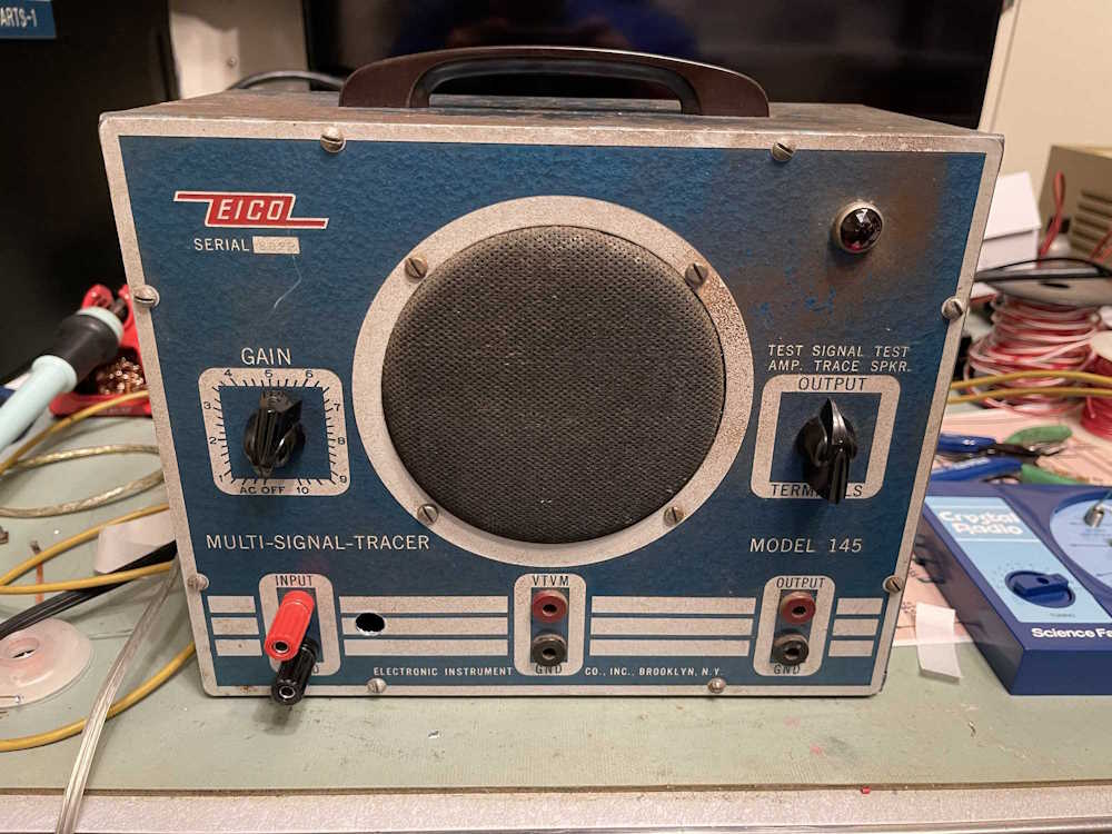
An Eico 145 Signal Tracer - Wrapup and final thoughts.
Monday, October 21, 2024 at 07:03:11
The signal tracer rebuild has been finished and happily amplifying sound again. What’s next? Here’s some thoughts on this device, and the rebuild process in general.
On the rebuild process itself:
1. Research the device.
Looking the device over and gathering things like schematics and assembly guides are a necessary first step, but don’t overlook the fact that these devices have been out there for decades. Plenty of people have had them in their possession, and there’s plenty of after the fact info available. Modifications, parts swaps to increase life, general deep dig things that may assist you in putting the thing back together. Read everything you can about the device before starting.
2. Some other tools you may need.
One of the greatest inventions I have on my bench is a tool called an orange stick. It’s not orange in color, but made from (traditionally) orange tree wood. It’s similar to the sticks that nail salons use in that it’s a double-ended stick with wedge-shaped ends - except that it’s longer. These are a soft wood that won’t mar parts, and can be used to push wires and wire-ends around for forming, as well as a soldering block for parts close together. They have a million uses. I highly suggest adding a pack of these to your tool kit.
Also, don’t be afraid to have more than one soldering iron on your bench. I regularly have my trusty 30W Weller, but keep an 80W unit handy when doing chassis work. You may find that having multiple wattages, multiple tips, or even multiple size units on the bench to be of use. You may even find a small butane torch to be useful here. Don’t limit yourself to just one.
3. Parts.
When you’re ordering parts, don’t use the crap you find on Amazon or eBay (unless you can verify it’s of known pedigree.) Get known parts from one of the supply houses. You don’t need to use the absolute top-tier part (unless you want to!) but get a good part. Always get an extra or two as well, in case you break something. It happens! Don’t go crazy buying 100s, but if you need 9, get 10 (and possibly a price break.) Be aware that some parts may have inductance (wire-wound resistors) and you want to avoid that kind of thing unless replacing like-for-like.
4. Be aware of voltages and values!
Capacitors are easily rated by the nomenclature printed on the part. Get at least the rated voltage and value here, but don’t go nuts. You don’t need a 1000V part where a 400V part was specified, but if all you can get is a 500V part, that’s fine. You’re not going to get the exact same values today for most of the stuff (except resistors) so don’t be afraid to go up a little in value. A 22uF part will easily replace a 20uF part in the power supply without issue - just don’t fall into the “more is better” trap because it’s not. Stay close to the rated design specs.
Resistors are a special case. For the most part, the 1/2W resistors used then are easily replaced today. However, be mindful of the voltages - you can be working with 300, 400, 500+ volts here, and parts need to be rated for the working voltage of the circuit. For example, if you have a resistor that’s rated 2W but it’s 2 inches long, then it’s probably a higher voltage device. Using a resistor rated for 500V in a 100V circuit isn’t going to hurt anything.
And, always remember you’re working with line and higher than line voltages here. Don’t be afraid of it, just give it the respect it deserves.
5. Grounds.
Grounds are important. Always make sure your contact points on the chassis are clean, and use washers that dig into the chassis if you can. Soldering those grounds to chassis for a good contact point will also work, but make sure you get a good connection otherwise oxides will build up and give you more grief than you started with. Good fluxing and a clean shiny spot for soldering is important here. Scotchbrite (plastic “steel” wool pads) is your friend here!
6. Signals.
It’s always been good practice to lay your filament and AC wires right on the chassis if possible, and to keep your low-level audio away from those, if possible. Keep it short and covered.
7. Don’t be afraid to modify!
Unless it’s of vital importance that a circuit be laid out the way the manufacturer did it, don’t sweat it if you see a better way. Add a terminal strip to bring parts out from hotspots. Add holes to mount new parts instead of trying to replace the exact old ones. Add a fuse. The manufacturers probably tried to work the assembly to use the least amount of extra parts, but you can take whatever luxuries you need.
8. Be mindful that you’re not the first owner.
There’s probably going to be modifications in the device. There may be added or missing parts. It may be that someone was trying to make the device do something else. Note these modifications before you begin, but don’t necessarily use them as a guide for rebuild unless you can see that it was trying to fix something.
9. Don’t be in a hurry.
The important advice with any kit. Take your time to lay out parts and wires. Check things as you go along, and check it all again when you’re done.
My thoughts on the device itself and rebuilding it…
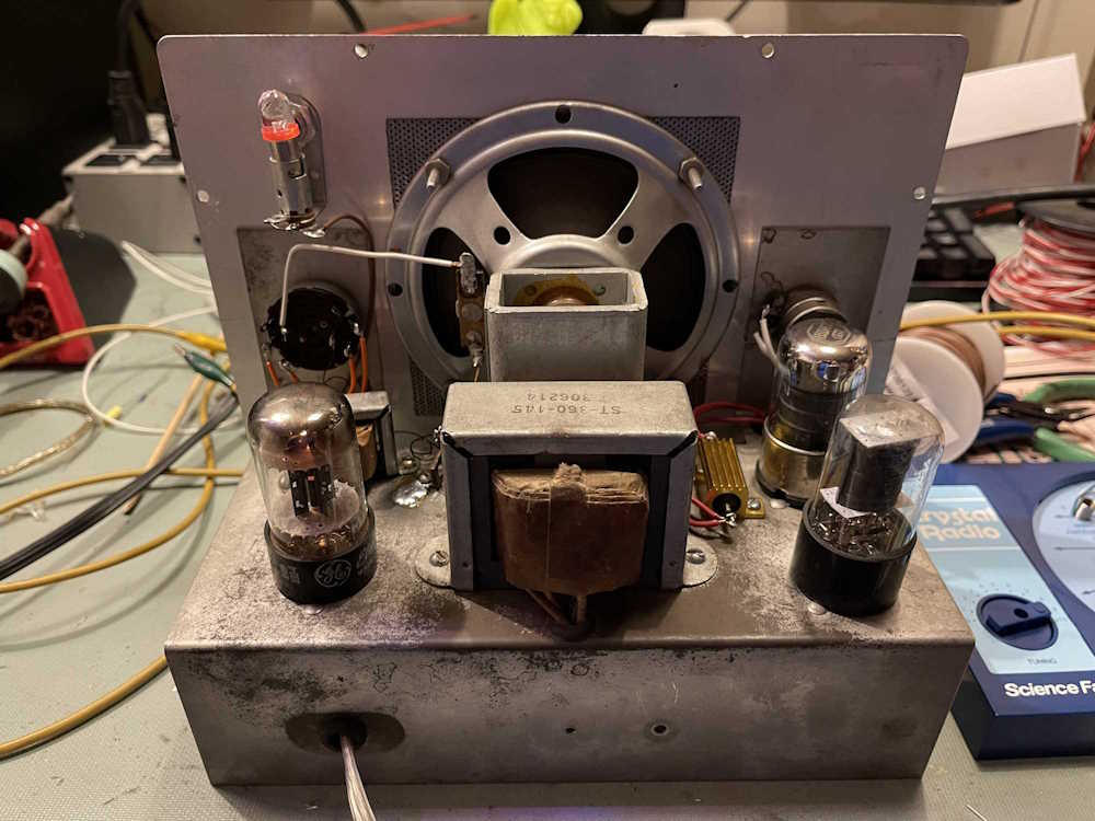
This is a fairly simple device in terms of operation. A power supply, a preamp, and a power amp. Not much going on here, but there were still some modifications made.
The 6K6 power output tube is run electrically hot in these, about 1W above rated specs according to what I’ve read and calculated. It was suggested that the cathode resistor, R5, be increased from 470ohm to 1kohm. I did so in this rebuild. C10 was missing on my device for some reason, and that was added back in. R5 is the resistor that provides current for the cathode, and C10 is a bypass capacitor to help improve fidelity of the amplified signal. It’s possible that C10 went bad at some point and was removed, as the device will operate just fine without it. I couldn’t see any evidence that it was ever there, however.
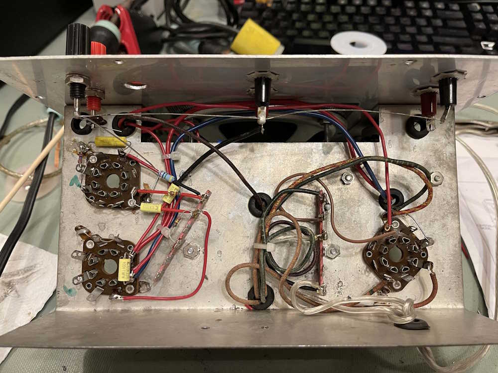
I’m not a purist, so I didn’t care how the power supply turned out. The old capacitor was discarded and two new parts were laid in it’s place. I decided to use a 500V non-inductive 25W aluminum resistor here, bolted directly to the top of the chassis, with the capacitors going to a ground also on the top. That probably offended some people, but I need functionality here, not a beauty contest winner. The reason I used the aluminum resistor is because it’s non-inductive, and was available to me.
Terminal strips were reused where possible, with new ones added. These allowed me to space the parts out more, which should help life in the terms of heat related death. It also allowed me to use two back-to-back diodes in the filament circuit to cut down on the voltage, since the device was designed to run on 110 - not the 125VAC we commonly see in the USA these days. Where something was grounded, the tabs for the terminal strips were soldered directly to the chassis to provide a good ground. It’s not the prettiest thing, but who cares.
Last, I had to remove and correct some of the modifications to this device. One of those nasty Amphenol microphone connectors on the front panel was removed (and needs to be filled at some point,) and the audio output transformer was bolted down. The audio transformer in the device didn’t fit the holes provided (device was narrower,) so I don’t know if this was because the original part was bad and was replaced at some point, if the chassis was drilled wrong, or what. A new hole for the transformer and a terminal strip to provide ground for the power supply mounted in the old hole fixed both those.
The only other thing is deciding how to fill the front panel hole. I could use a BNC connector, but since this probably will never see IF frequencies, do I care? Originally, I though about just plugging it with a plastic plug I had laying around, but I’ve kind of warmed up to using that hole as a ground tie point, or maybe just a tie point in general that’s not connected to anything internally. Who knows at this point.
During the final check, I discovered two errors.
The first one was I put a 510k resistor where a 10M should be. I think I know what happened here - I had a 10M there, but didn’t like the way it laid. I pulled it out, saw the blue stripe, and looked at the blurry schematic. I then assumed it was 510k and put that back in place. It’s been long enough that I forgot I actually bought 10M parts, so this was completely my fault.
The second was the b+ connection to the junction of R3/R4 wasn’t laid in. I remember looking at this and thinking I already had too much crap on the one tie point, and intended on going back later to put this in. “Later” just happened to be the last step, so this is both my fault and me claiming I meant to do that.
There’s still that hole in the front panel. I think I’m just going to go with my original thought and plug it.
Some final notes
One of the things I noticed about this particular tracer is there’s a lot of noise / hum in the output, unlike other tracers. Even though I tried to lay power and ground on the chassis to help mitigate this, it’s still there - and it’s loud.
Why? Well…if you look at the tracer itself, the audio input lines are basically just big antenna wires that run the entire length of the device. Any signals floating around inside of there - from the transformer, the AC input, anything really - is going to go right into the signal path.
I don’t see any way around this noise, as the device wasn’t really designed with noise in mind. It is what it is, and that’s all it’s going to be - EICO’s low-end signal tracer. It does it’s job, but you’re going to have noise.
But…that’s it! This device has been well used, looks like it’s Seen Things - that’s part of the charm of this device. It’s rusted and has spray paint on it and some scratches. It’s a piece of equipment that’s worked it’s entire life, and it’s ready to do it again. I’m not interested in “restoration,” I want the device to look like it does. So…crank up the 1KHz and let’s get some radios repaired!
Recapping the journey (and the device!)
Purchasing the unit at the 2023 Breezeshooters Hamfest in Butler PA.
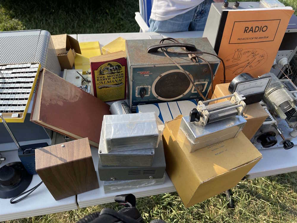
It was obviously a kit unit.
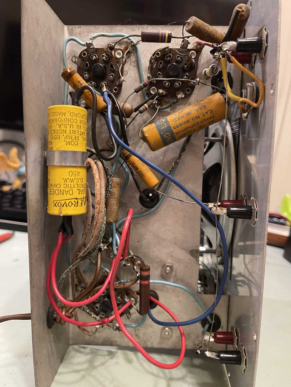
Some cleanup on the physical parts of the device, then removing everything.
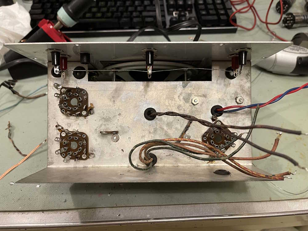
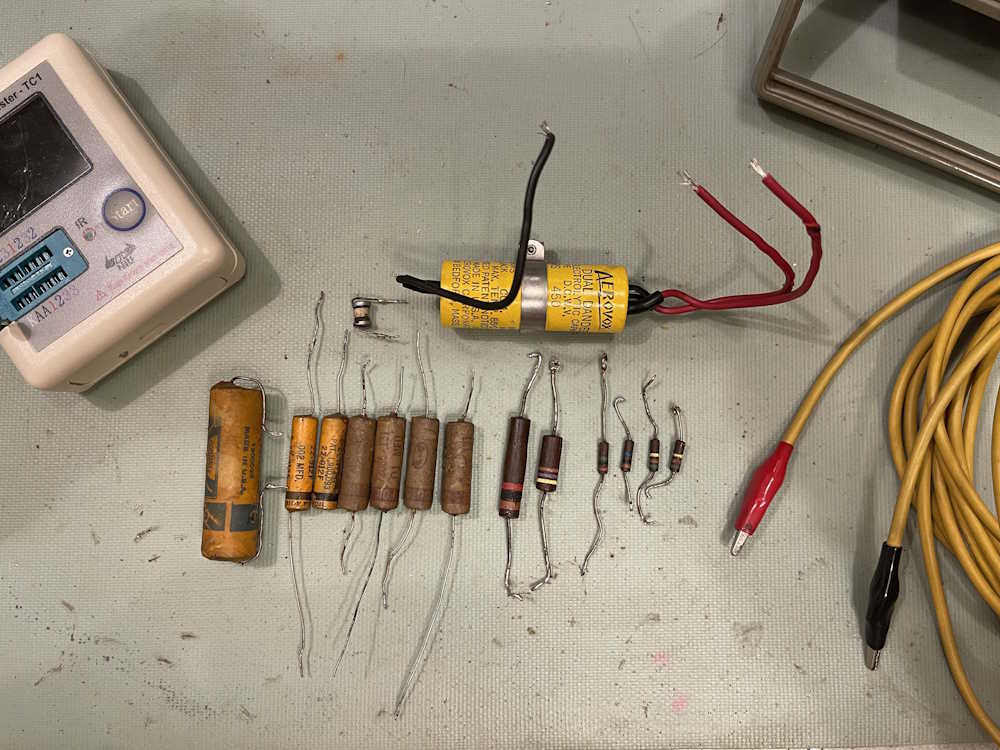
All the parts are out.
Putting things back in, one part at a time.
It lives!
And, we’re done.
The entire series from start to finish:
Purchasing the unit at Butler 2023: https://wereboar.com … fest-2023-butler-pa/
Initial evaluations on the device: https://wereboar.com … o-145-signal-tracer/
Part 0 - Some thoughts on parts inside: https://wereboar.com … ignal-tracer-part-0/
Part 1 - Collecting ideas and parts: https://wereboar.com … ignal-tracer-part-1/
Part 2 = Cleaning the device: https://wereboar.com … ignal-tracer-part-2/
Part 3 - Let’s get some parts: https://wereboar.com … ignal-tracer-part-3/
Part 4 - Some more prep work: https://wereboar.com … ignal-tracer-part-4/
Part 5 - Let’s take it apart: https://wereboar.com … ignal-tracer-part-5/
Intermission - Component notes: https://wereboar.com … cer-component-notes/
Part 6a - Starting the rebuild: https://wereboar.com … tarting-the-rebuild/
Part 6b - The power supply: https://wereboar.com … ng-the-power-supply/
Part 6c - Halfway there: https://wereboar.com … -to-run-a-few-wires/
Part 6d - We’re almost done: https://wereboar.com … art-6d-almost-there/
part 6e - The parts are in: https://wereboar.com … the-rebuild-is-done/
Part 7 - Check your work: https://wereboar.com … -checking-your-work/
Part 8 - And, it’s done: https://wereboar.com … art-8-and-were-done/
Wrapup - You’re reading it now.
It’s been over a year since that first evaluation, thank you for coming along on the journey. I think the next device will be the signal generator I picked up at the Scioto Valley hamfest. Stay tuned for more good junk, I mean equipment!
Previous part of this series: https://wereboar.com … art-8-and-were-done/